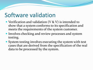
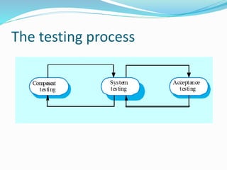
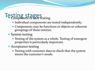
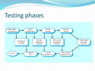
Download to read offline
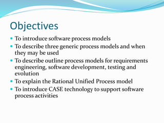
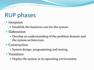
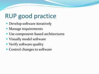
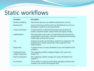
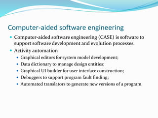


The document discusses software processes and models. It describes objectives of introducing process models and activities like requirements engineering, design, testing and evolution. Generic process models covered are waterfall, evolutionary development and component-based engineering. Iterative models like incremental delivery and spiral development are also introduced. The Rational Unified Process model and role of computer-aided software engineering in supporting process activities are also summarized.