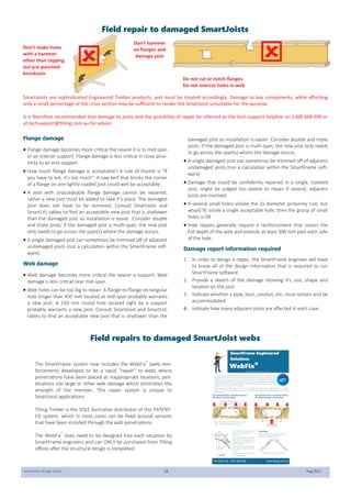
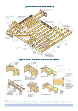
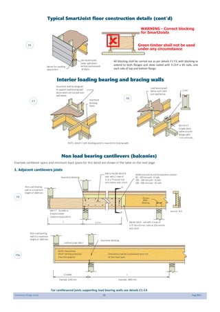
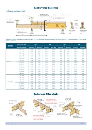
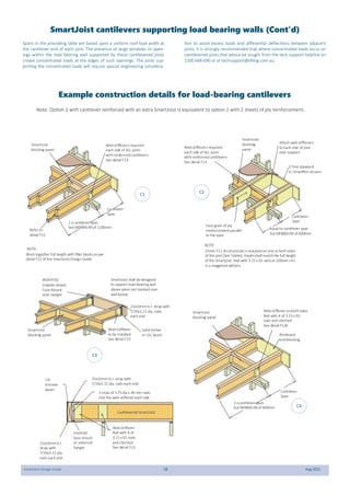
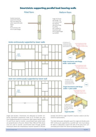
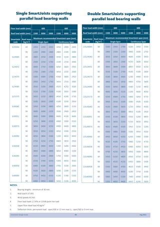
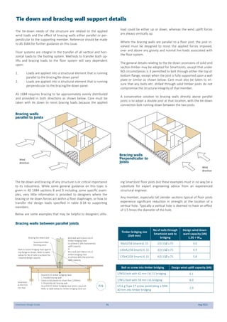
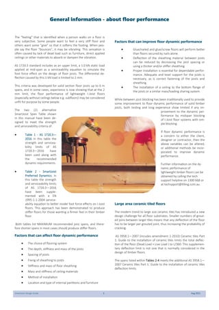
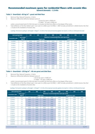
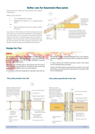
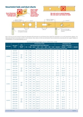
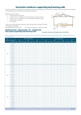
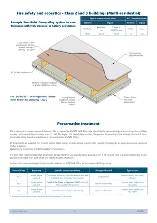
SmartJoist®
Design Guide
Edition 2
2021
Table of Contents
Scope of this publication and engineering Certification 1
General Information—About floor performance 3
Recommended maximum spans
- Table 1 4
- Table 2 4
- Table 3 5
- Table 4 5
SmartJoist design/effective span 6
Safety and SmartJoists installation 7
Handling and storage 7
Durability and exposure to moisture 8
SmartJoist—General Information End nailing, rimboard and sheet nailing 8
SmartJoist floor construction details
1. Forces at SmartJoist supports 9
2. End support blocking
1. Simplified solution 10
2. Engineering Solution 11
SmartJoist/SmartRim blocking capacities 13
Penetrations within SmartJoist/SmartRim blocking 13
Joist hangers 14
General connector installation details 17
Field repair to damaged SmartJoists 18
Typical SmartJoist floor framing 19
Typical SmartJoist floor construction details
- End blocking 19
- Interior loadbearing and bracing walls 19
- Non loadbearing cantilevers 20
- Backer and filler blocks 21
- Concentrated loads on SmartJoists 23
- Multiple SmartJoist members 23
- SmartJoist multi-joist clips 23
- Limited end notching at supports 24
- Example fixing to steel beams 25
- Example fixing to masonry walls 26
Joist/beam connections supporting concentrated loads 26
Multiple member beams supporting SmartJoists 27
Rafter cut for SmartJoist floor joists 30
Design for Fire 30
SmartJoist floor setdowns 31
Building envelope water tightness 31
Brick ledge cantilever construction details 32
SmartJoist hole and duct charts 35
Openings within SmartJoist floors 36
SmartJoist cantilevers supporting loadbearing walls 37
SmartJoists under parallel load bearing walls 39
Tie down and bracing wall details 41
Cyclone rod tie down for cantilevered floors joists 44
SmartJoists as rafters 45
SmartJoist box gutter details 46
Table of Contents (cont’d)
SmartFrame bevelled bearing plates 47
Strong-Drive® SDWC Truss screws 47
Typical SmartJoist roof details 48
SmartJoist roof cassettes 51
Safe loading of materials on SmartJoist working platforms 52
Fire safety and acoustics Class 2 and class 3 buildings 53
Preservation treatments 54
Adhesive and formaldehyde fact sheets 55
SmartJoist Design Guide 1 Aug 2021
This Design Guide and Load Tables assists in the selection of
SmartJoists for most of the common structural arrangements met
in domestic construction. The Tilling Timber website
(www.tilling.com.au) and SmartFrame software, in conjunction with
this manual, provides an unparalleled level of design capacity for
SmartFrame engineered timber products.
While specific details are given on suitable methods of developing
lateral restraint, the methods of providing adequate support, ade-
quate anchorage against wind uplift and overall structural stability
are outside the scope of this publication.
Information on the above matters can be obtained from AS 1684
Residential timber-framed construction code or from a structural
engineer experienced in timber construction.
Tilling Timber Pty Ltd has structural engineers on staff who can be
contacted for advice on matters concerning the use of its engi-
neered timber products in timber construction on the tech support
helpline on 1300 668 690 or at techsupport@tilling.com.au.
Substitution of other products
All load tables in this document are designed using in-grade tested
properties for I-Joists distributed as SmartJoists. Other manufactur-
ers I-Joists may have different properties and, therefore, cannot be
designed using these span tables.
Copyright
Copyright of this publication remains the property of Tilling Timber
Pty Ltd, and reproduction of the whole or part of this publication
without written permission from Tilling Timber Pty Ltd is prohibited.
NCC Evidence of suitability
Part A5.2 of the NCC documents the six (6) methods a manufactur-
er may use to support that the use of a material, product, form of
construction or design meets a Performance Requirement or a
Deemed-to-Satisfy Provision.
Two (2) of the six methods are adopted below to provided Evidence
of suitability that SmartJoists meet the Performance Requirements.
A5.2(1)(e) A certificate or report from a professional engineer or
other appropriately qualified person.
As a professional engineer, qualified and experienced in timber
engineering, I certify that the use of the SmartJoist members as
shown in these tables, and installed in accordance with the provi-
sions of this Design Guide, will comply with the requirements of the
Building Code of Australia. These span tables have been prepared in
accordance with standard engineering principles, the relevant test
reports and Australian standards:
 AS 1720.3 Timber structures Part 3: Design criteria for tim-
ber-framed residential buildings
 AS 1720.1 Timber Structures - Design Methods
 AS 4055 Wind loads for Houses
 ASTM D 5055 Standard specification for establishing and
monitoring structural capacities of prefabricated wood I-
Joists
 ISO 22389 -1 Timber Structures - Bending strength of I-
beams. Part 1: Testing, evaluation and characterization
Craig Kay RPEng, BDC0730, PE0001869, RPEQ5100, CC5635C, NER
National Product Engineer
A5.2(1)(f) Another form of documentary evidence, such as but not
limited to a Product Technical Statement.
A SmartJoist Product Technical statement is available on request
from the techsupport helpline on 1300 668 690 or at techsup-
port@tilling.com.au.
This Product Technical Statement —
(i) demonstrates that the SmartJoist fulfils the performance re-
quirements of the NCC; and
(ii) sets out the basis on which it is given and the extent to which
relevant standards, specifications, rules, codes of practice or other
publications have been relied upon to demonstrate it fulfils specific
performance requirements of the NCC.
Scope of this publication
The information contained in this product brochure is current as Aug 2021 and is based on data available to Tilling Timber Pty Ltd at the time of going to print. Tilling Timber Pty Ltd has
used its reasonable endeavours to ensure the accuracy and reliability of the information contained in this document and, to the extent permitted by law, will not be liable for any inac-
curacies, omissions or errors in this information nor for any actions taken in reliance on this information. Tilling Timber Pty Ltd reserves the right to change the information contained in
this document without prior notice. It is important that you call the tech support helpline on 1300 668 690 to confirm that you have the most up to date information available.
SmartJoist Design Guide 2 Aug 2021
“The strength is in the
engineering”
The SmartFrame Engineered Wood System is made up of:
 World class engineered timber products:
1. SmartJoist
2. SmartLVL
3. SmartLam GLT
4. Tecbeam
 Unique SmartFrame Structural Design, Detailing and
Estimating Software
 Full engineering support and technical advice from
experienced engineers and field staff free of charge
on our unique tech support helpline 1300 668 690.
SmartJoists
The strength is in the engineering: Strong. Stiff. Reliable.
SmartJoists are engineered for heavy performance. We start with
ultrasonically graded LVL, bonded with exterior adhesive for more
load carrying capacity.
The webs are made from stable, strong Oriented Strand Board (OSB)
for superior strength and consistent performance. SmartJoists are
more uniform than solid sawn joists. They stay straighter and are
manufactured with no camber, so there is no chance of crown down
or upside down installation. They resist shrinking, twisting, warping
and splitting for squeak resistant floors and quality roofs and ceil-
ings.
Holes may be easily cut in the web according to the tables on page
30, allowing ducts and utilities to be run through the joists. Pre-
punched 40 mm knockout holes are provided in the web for small
diameter services or wiring.
Save Time and Money: Because they weigh less than solid sawn
joists, SmartJoists are easier to install, saving construction time and
cost. Their greater load carrying capacity allows you to space them
further apart, so it takes fewer to build the average floor or roof.
And with five (5) depths from 200 to 400 mm, you will never have to
compromise your design. So whether your plans call for cantilever
beams in balconies, cathedral roofs or high pitched roof slopes,
SmartJoists are the perfect choice.
An Environmentally Sound Choice: In addition to being cost effec-
tive, SmartJoists are also an environmentally sound choice because
they are made of a renewable resource – wood. So they are a better
choice for building.
SmartJoists have a certified Chain of Custody system to PEFC.
SmartFrame Software: Our unique SmartFrame design, detailing
and estimating software offers you unparalleled design and esti-
mating capabilities with engineered timber. You will get accurate
designs for a wide variety of applications, printouts and joist layouts.
Limitations of use - SmartJoists: SmartJoists are to be used in dry
interior environments only, fully enclosed from exposure to exterior
moisture. SmartJoists are suitable for subfloor applications provided
that the subfloor space is ventilated as per the NCC requirements.
This means that SmartJoists must not be exposed to environments
where the equilibrium moisture content of the joist will exceed 18%.
Tilling Timber will not guarantee SmartJoists that have been left
exposed to the weather either prior to or during construction for
more than 90 days.
Detailing such as cladding or lining must be used in moisture laden
environments (commercial kitchens, bathrooms, wet industrial are-
as, saunas, swimming pool and spa rooms etc.) and constructed in
such a way as to prevent exposure of the SmartJoist to moisture.
SmartJoists may be used in applications which are often exposed
externally (gable ends, eaves, floor joists applications in elevated
houses, cantilevered joists etc.) but must be sufficiently enclosed
with a suitable cladding, lining etc. to completely prevent the expo-
sure of the SmartJoist to moisture.
Tilling Timber guarantees that SmartFrame Engineered Timber products have been manufactured to
exacting standards and are free from defects in workmanship and materials.
At Tilling Timber, we take great pride in SmartFrame products, so if you bring to our attention prob-
lems such as squeaks that you believe are caused by our products, we guarantee that a technical
representative will contact you promptly to evaluate the issues and provide advice to help solve the
problem.
Providing that any SmartFrame product is correctly designed, handled and installed, any problem
caused by an unlikely defect will promptly be remedied at no cost to you.
This guarantee remains valid for the expected life of your home.
Tilling Timber Pty Ltd
31-45 Orchard Street
Kilsyth Vic 3137
Priority call: 1300 668 690 e-mail: techsupport@tilling.com.au
SmartFrame Consumer Product Warranty
SmartJoist Design Guide 3 Aug 2021
The “feeling” that is identified when a person walks on a floor is
very subjective. Some people want to feel a very stiff floor and
others want some ”give” so that it softens the footing. When peo-
ple say the floor “bounces”, it may be vibrating. This sensation is
often caused by lack of dead load such as furniture, direct applied
ceilings or other materials to absorb or dampen the vibration.
AS 1720.3 standard includes as an upper limit, a 1.0 kN static load
applied at mid-span as a serviceability equation to simulate the
foot force effect on the design of floor joists. The differential de-
flection caused by this 1 kN load is limited to 2 mm.
This criteria was developed for solid section floor joists up to 6 m
spans, and in some cases, experience is now showing that at the 2
mm limit, the floor performance of lightweight I-Joist floors
(especially without ceilings below e.g. subfloors) may be considered
unfit for purpose by some people.
The two (2) alternative
SmartJoist Span Table shown
in this manual have been de-
signed to meet the strength
and serviceability criteria of:
 Table 1 - AS 1720.3—
2016 In this table the
strength and servicea-
bility limits of AS
1720.3—2016 have
been used along with
the recommended
dynamic requirements.
 Table 2 - SmartJoist
Preferred Dynamics. In
this table the strength
and serviceability limits
of AS 1720.3—2016
have been supple-
mented with a EN
1995-1-1-2004 service-
ability equation to better model foot force effects on I-Joist
floors. This approach has been demonstrated to produce
stiffer floors for those wanting a firmer feel in their timber
floor.
Both tables list MAXIMUM recommended joist spans, and there-
fore shorter spans in most cases should produce stiffer floors.
Factors that can affect floor dynamic performance
 The choice of flooring system
 The depth, stiffness and mass of the joists
 Spacing of joists
 Fixing of sheathing to joists
 Stiffness and mass of floor sheathing
 Mass and stiffness of ceiling materials
 Method of installation
 Location and type of internal partitions and furniture
Factors that can improve floor dynamic performance
 Glue/nailed and glue/screw floors will perform better
than floors secured by nails alone.
 Deflection of the sheathing material between joists
can be reduced by decreasing the joist spacing or
using a thicker and/or stiffer sheathing.
 Proper installation is essential for dependable perfor-
mance. Adequate and level support for the joists is
necessary, as is correct fastening of the joists and
sheathing.
 The installation of a ceiling to the bottom flange of
the joists or a similar mass/loading sharing system.
While between joist blocking has been traditionally used to provide
some improvement to floor dynamic performance of solid timber
joists, both testing and long experience show limited if any im-
provement to the dynamic per-
formance by midspan blocking
of I-Joist floor systems with sim-
ple blocking.
If floor dynamic performance is
a concern to either the client,
designer or contractor, then the
above variables can be altered,
or additional methods be incor-
porated to improve dynamic
performance.
Further information on the dy-
namic performance of
lightweight timber floors can be
obtained by calling the tech
support helpline on 1300 668 or
at techspport@tilling.com.au.
Large area ceramic tiled floors
The modern trend to large size ceramic tiles has introduced a new
design challenge for all floor substrates. Smaller numbers of grout-
ed joins between larger tiles means that any deflection of the floor
has to be larger per grouted joint, thus increasing the probability of
cracking.
AS 3958.1—2007 (incudes amendment 1-2010) Ceramic tiles Part
1: Guide to the installation of ceramic tiles limits the total deflec-
tion of the floor (Dead Load + Live Load ) to L/360. This supplemen-
tary deflection limit is not one that is normally considered in the
design of timber floors.
The spans listed within Tables 2-4 meets the additional AS 3958.1—
2007 Ceramic tiles Part 1: Guide to the installation of ceramic tiles
deflection limits.
General information - about floor performance
SmartJoist Design Guide 4 Aug 2021
In compiling the span tables in this manual, the requirements of the relevant Australian standards and codes along with established Industry
standard design guidelines for Residential Construction have been followed. In particular, the following codes and references have been used:
 AS 1720.3 Timber structures. Part 3: Design criteria for timber-framed residential buildings
 AS 1720.1 Timber Structures - design methods
 AS 4055 Wind loads for houses
 AS/NZS 4063 Characterisation of structural timber
 ASTM D 5055 Standard specification for establishing and monitoring structural capacities of prefabricated wood I-Joists
Serviceability criteria:
Max permanent load deflection - lesser of span / 300 or 15 mm (j2 = 2)
Max live load deflection - lesser of span / 360 or 9 mm
Table 1 - AS 1720.3—2016 Floor dynamics criteria
1. Minimum floor Natural Frequency - 8 Hertz
2. Maximum differential deflection between joists of 2 mm under a concentrated load of 1.0 kN mid-span to simulate the foot force
effect on the design of floor joists.
Table 2 - SmartJoist Preferred floor dynamics criteria
1. Minimum floor Natural Frequency - 8 Hertz
2. Maximum differential deflection between joists of:
- 1.8 mm for spans ≤ 4200 mm
- 17,500/L1.1
for span ≥ 4200 mm (for L in mm)
under a concentrated load of 1.0 kN mid-span to simulate the foot force effect on the design of floor joists.
Recommended maximum spans for lightweight residential floors
Loadings: Permanent Loading G: self weight + 40 kg/m2
+ 0.5 kPa of live load permanently applied, live load Q: 1.5 kPa or 1.8 kN point live load
General domestic - 1.5 kPa
Joist spacing (mm) 300 400 450 600 300 400 450 600
SmartJoist code
Self weight
(kg/m)
Maximum recommended floor joist span (mm)
Single span Continuous span
SJ20044 2.7 4750 4400 4200 3750 5400 5000 4800 4300
SJ24040 2.8 5200 4800 4650 4250 5900 5550 5300 4900
SJ24051 3.2 5500 5050 4950 4550 6200 5700 5600 5100
SJ24070 4.0 5900 5450 6300 4900 6600 6150 6000 5500
SJ24090 5.1 6250 5800 5600 5200 7000 6500 6350 5850
SJ25570 4.4 6100 5650 5500 5100 6900 6400 6200 5750
SJ30040 3.1 5900 5450 5300 4900 6650 6100 5900 5650
SJ30051 3.6 6250 5800 5600 5200 7000 6500 6250 5900
SJ30070 4.4 6700 6200 6050 5600 7500 6900 6700 6300
SJ30090 5.6 7150 6600 6400 5900 7950 7350 7100 6700
SJ36058 4.5 7200 6700 6500 6000 8150 7500 7250 6900
SJ36090 6.0 7900 7300 7100 6550 8850 8150 7900 7500
SJ40058 4.5 7550 7000 6800 6300 8750 8150 7900 7300
SJ40090 6.3 8400 7750 7550 6950 9400 8650 8400 7800
Joist spacing (mm) 300 400 450 600 300 400 450 600
SmartJoist code
Self weight
(kg/m)
Maximum recommended floor joist span (mm)
Single span Continuous span
SJ20044 2.7 4650 4200 3900 3600 5400 4750 4500 4150
SJ24040 2.8 5100 4500 4350 4050 5900 5200 4900 4500
SJ24051 3.2 5400 4800 4650 4350 6200 5500 5200 4800
SJ24070 4.0 5850 5250 4950 4650 6700 5900 5600 5100
SJ24090 5.1 6150 5550 5250 4950 7150 6200 5950 5450
SJ25570 4.4 6150 5400 5100 4800 6900 6100 2800 5300
SJ30040 3.1 5850 5100 4950 4650 6700 5900 5600 5150
SJ30051 3.6 6150 5400 5250 4950 7100 6200 5900 5450
SJ30070 4.4 6750 5850 5700 5250 7650 6700 6350 5850
SJ30090 5.6 7050 6300 6000 5550 8100 7100 6750 6200
SJ36058 4.5 7200 6300 6150 5700 8250 7200 6850 6300
SJ36090 6.0 7950 6900 6600 6150 9000 7850 7450 6850
SJ40058 4.5 7500 6600 6300 6000 8700 8100 7800 7350
SJ40090 6.3 8400 7350 7050 6600 9500 8300 7900 7250
SmartJoist Design Guide 5 Aug 2021
Table 3 - SmartJoist –65 kg/m2
- grout and tiled floor
1. Minimum floor Natural Frequency - 8 Hertz
2. Maximum differential deflection between joists of:
- 1.8 mm for spans ≤ 4200 mm
- 17,500/L1.1
for span ≥ 4200 mm
under a concentrated load of 1.0 kN mid-span to simulate the foot force effect on the design of floor joists.
3. Total deflection of the floor (Dead Load + Live Load ) to L/360 as per AS 3958.1—2007 (incudes amendment 1-2010) Ceramic tiles Part
1: Guide to the installation of ceramic tiles
Table 4 - SmartJoist –135 kg/m2
- 40 mm grout and tiled floor
1. Minimum floor Natural Frequency - 8 Hertz
2. Maximum differential deflection between joists of:
- 1.8 mm for spans ≤ 4200 mm
- 17,500/L1.1
for span ≥ 4200 mm
under a concentrated load of 1.0 kN mid-span to simulate the foot force effect on the design of floor joists.
3. Total deflection of the floor (Dead Load + Live Load ) to L/360 as per AS 3958.1—2007 (incudes amendment 1-2010) Ceramic tiles Part
1: Guide to the installation of ceramic tiles
Recommended maximum spans for residential floors with ceramic tiles
Loadings: Permanent Loading G: self weight + 65kg/m2
+ 0.5 kPa of live load permanently applied, live load Q: 1.5 kPa or 1.8 kN point live load
General domestic - 1.5 kPa
Loadings: Permanent Loading G: self weight + 135 kg/m2
+ 0.5 kPa of live load permanently applied, live load Q: 1.5 kPa or 1.8 kN point live load
Joist spacing (mm) 300 400 450 600 300 400 450 600
SmartJoist code
Self weight
(kg/m)
Maximum recommended floor joist span (mm)
Single span Continuous span
SJ20044 2.7 4500 4050 3900 3450 5400 4650 4500 4050
SJ24040 2.8 5100 4500 4350 3900 5850 5100 4800 4500
SJ24051 3.2 5400 4800 4650 4200 6150 5400 5100 4800
SJ24070 4.0 5850 5250 4950 4650 6750 5850 5500 5100
SJ24090 5.1 6150 5550 5250 4950 7200 6300 5850 5400
SJ25570 4.4 6000 5400 5100 4800 6900 6100 5700 5250
SJ30040 3.1 5850 5100 4950 4650 6700 5850 5550 5100
SJ30051 3.6 6150 5400 5250 4950 7050 6150 5850 5400
SJ30070 4.4 6600 5850 5700 5250 7600 6600 6300 5850
SJ30090 5.6 6900 6300 6000 5550 8100 7050 6750 6150
SJ36058 4.5 7200 6300 6150 5700 8200 7200 6750 6300
SJ36090 6.0 7650 6900 6600 6150 9000 7800 7500 6900
SJ40058 4.5 7500 6600 6300 6000 8500 7500 7050 6600
SJ40090 6.3 8250 7350 7050 6600 9600 8250 7800 7200
Joist spacing (mm) 300 400 450 600 300 400 450 600
SmartJoist code
Self weight
(kg/m)
Maximum recommended floor joist span (mm)
Single span Continuous span
SJ20044 2.7 3750 3300 3150 2850 4700 4400 4300 3900
SJ24040 2.8 4200 3750 3600 3300 5200 4850 4700 4350
SJ24051 3.2 4500 4050 3900 3450 5500 5100 4950 4600
SJ24070 4.0 5100 4500 4350 3900 5850 5450 5250 4900
SJ24090 5.1 5400 4950 4650 4200 6100 5700 5550 5150
SJ25570 4.4 5250 4800 4500 4050 6100 5650 5500 5100
SJ30040 3.1 5100 4500 4350 3900 5900 5500 5350 4950
SJ30051 3.6 5400 4950 4650 4200 6200 5800 5600 5250
SJ30070 4.4 5850 5400 5250 4650 6600 6200 6050 5600
SJ30090 5.6 6150 5850 5550 5100 6950 6500 6300 5900
SJ36058 4.5 6300 5850 5700 5250 7150 6700 6450 6000
SJ36090 6.0 6900 6450 6300 5850 7700 7200 6950 6450
SJ40058 4.5 6600 6150 6000 5550 7500 7050 6850 6350
SJ40090 6.3 7350 6750 6600 6150 8150 7600 7400 6900
SmartJoist Design Guide 6 Aug 2021
Recommended maximum spans for residential floors (cont’d)
Flooring
Spans are suitable for solid timber, particle board and ply flooring. Floor sheathing glued and nailed to the joists will improve floor rigidity.
Where a heavy overlay material is to be applied, such as thick mortar bed tiled or slate floors, the permanent load allowance should be in-
creased to 1.2 kPa. A reduction of joist spacing can be used to accommodate this extra permanent load. A satisfactory result can be achieved
by adopting the maximum spans for 600 mm and 450 mm spacing but installing the joists at 450 mm and 300 mm spacing respectively.
Continuous spans
For beams which are continuous over two unequal spans, the design span and the "resultant span description" depend on the percentage
difference between the two spans as shown below:
Effective span Resultant span description
Span difference
10% max main span continuous
10 - 30% 1.1 x main span continuous
above 30% diff main span single
Main span Second span
span difference =
(main span - second span)
X 100
(main span + second span)
SmartJoist Design /Effective span
Normal structural analysis uses the centreline representation of
the member. The term “span” can be defined in a number of ways
and these are defined as follows:
Clear Span. This is the distance between the faces of any support.
It is generally the one easiest to measure and read from the draw-
ings.
Nominal span/centre-line span. This is the distance between the
centre of the supports. This span is used to determine bending
moments and deflections for continuous spaning members.
Design span/Effective span. This is the span used for single span
members to determine the bending moment, the slenderness of
bending members and the deflections. In NZS 3603 this is the
dimension referred to as “L”, and is defined below:
Design span/Effective span is the distance between -
 The centre of the bearing at each end of a beam where
the bearing lengths have NOT been conservatively sized
 The centre of notional bearing that have been sized appro-
priately, where the size of the bearing IS conservative.
Diagram (a) shows beam where bearings have
been designed appropriately. The effective
span is taken as the distance between the
centre of each bearing area
Diagram (b) shows beam where bearings at
each end have been oversized. (This is fre-
quently the case for beams that bear onto
brickwork or concrete walls where the thick-
ness of the wall is in excess of the area
required to give the beam bearing capacity).
To find the correct effective span:
1. Calculate the minimum bearing re-
quired to carry the loads satisfactorily
2. Add minimum bearing length to “clear
span” distance
Area of support
required for
bearing
lengthof original
bearing (oversized)
Lengthof
effective
bearing
Clear span (distance
between face of supports)
Effective (design) span
Clear span (distance
between face of supports)
Effective (design) span
Centre-line span (distance between centresof supports)
(a)
(b)
SmartJoist Design Guide 7 Aug 2021
Accidents can be avoided under normal
conditions by following these guidelines:
1. Brace each joist as it is erected. Joists must be nailed to
supports and all hangers, blocking, rim joists. X - bridging at
supports must be completely installed and properly nailed.
(see general notes and details)
2. Brace the ends of cantilevers (overhangs) with closure
panels, rim joist or x - bridging (see general notes and de-
tails)
3. Lateral brace the top flange of each joist, to prevent side-
ways buckling or rollover which may occur under light con-
struction loads, such as a worker and/or a layer of un-
nailed sheathing. Fully installed permanent sheathing or
temporary struts to the top flange of each joist (see
‘Typical SmartJoist floor framing’) can accomplish lateral
bracing. Temporary struts must be nailed to a lateral re-
straint at the end of bay such as a braced wall or tempo-
rary (or permanent) sheathing nailed to the first 1200 mm
of the joist at the end of the bay (see ‘Typical floor or roof
framing’)
4. Permanent sheathing must be completely installed and
properly nailed before additional loads can be placed on
the system
5. The integrity and safe use of these products can be seriously
impaired if they are damaged. Do not install any damaged
products. Contact your SmartFrame representative or the
tech support helpline on 1300 668 690 if any product dam-
age is noted.
Do not allow workers or loads on
SmartJoists until all blocking, hangers, rim
joists, nailing and temporary bracing are
installed as specified below. Serious acci-
dents or injury can result from failure to
follow these guidelines.
Safety Warning
Handling and storage of SmartJoists
SmartJoists should be stacked in the upright position to avoid any damage during handling or storage.
 Store SmartJoists flat on a hard, dry surface
 If surface isn't paved, the ground should be covered
with a polythene film
 Keep covered with waterproof material that allows
bundles to "breathe"
 Use bearers (bolsters) between the ground and the
first bundle (4 metre max spacing)
 Use 100 x 50 timber flat between bundles at same
spacing as bolsters
 Take great care to rewrap remaining material after
opening bundles
 Wood "grows" in thickness and depth when allowed
to get wet....KEEP DRY!
 Wood with high MC has short term reduction in
Characteristic Strengths …. KEEP DRY!
 Under NO circumstances are stored SmartJoists to be
in contact with the ground.

Bearers at a
maximum
of 4000 mm
centres
Use bearers to keep stacked material away from damp surfaces. Align bearer vertically

SmartJoist Design Guide 8 Aug 2021
SmartJoists - General information
SmartJoists are manufactured with Douglas Fir (Oregon) flanges
with OSB webs, both having a durability rating of class 4, the equiv-
alent rating as some Ash type Eucalypts. Untreated SmartJoists
should therefore not be used where the equilibrium moisture con-
tent is likely to remain above 18 % for an extended period.
Untreated SmartJoists are suitable in the internal, fully protected,
ventilated and the external above ground, protected zones of the
structure as shown in appendix B of AS 1684. Untreated SmartJoist
is not suitable for external above ground, exposed or humid indoor
conditions, such as swimming pool enclosures.
Moisture effects on SmartJoists
SmartJoist is supplied WITHOUT any short term construction sealer,
but once framed into a structure may be exposed to the weather
for a limited time (not greater than 3 months) without negative
affect, BUT, it may exhibit some effects of this exposure.
The wood fibre in SmartJoists, like all wood products, is hygroscop-
ic, which means it has an affinity for water. The wood fibre in
SmartJoist will readily take up and release moisture in response to
changes in the local environment. Moisture exposure will lead to
dimensional change. While the products will withstand normal
exposure, excessive exposure during distribution, storage or con-
struction may lead to dimensional changes that affect serviceability.
These changes include twisting, bowing or expansion to dimensions
to beyond the specified tolerance of the product in the “as-
manufactured” condition.
As an organic material, mould and mildew may grow on untreated
wood products if moisture is present. Prolonged periods of high
moisture may also support the growth of wood decay fungi, which
is another reason to follow proper methods of storage and handling
of SmartJoists.
The table below shows the moisture content of SmartJoists as a
function of humidity.
Wetting during construction may lead to temporary elevated mois-
ture content and dimensional changes. Once covered, the
SmartJoists will ultimately dry and re-equilibrate to the ambient
humidity conditions, but some expansion or swelling may remain
after drying.
Durability and exposure to moisture
Moisture content of wood products %(1)
Relative Humidity % LVL Flange MC OSB web
10 1.2 0.8
20 2.8 1.0
30 4.6 2.0
40 5.8 3.6
50 7.0 5.2
60 8.4 6.3
70 11.1 8.9
80 15.3 13.1
90 19.4 17.2
(1). Approximate moisture content at 210
C
1. Joists should be accurately placed at not more than the nomi-
nated maximum centre to centre spacing so as to provide the
support required for flooring and load bearing walls or concen-
trated loads
2. Supports shall be level, dry and have at least the rigidity im-
plied by good framing practice and/or the design criteria speci-
fied for supporting components in AS 1684. (A moisture barri-
er is recommended where support is directly to masonry or
brickwork.)
3. Except where otherwise noted, 30 mm minimum bearing is
required at joist ends and 42 mm minimum bearing is required
at intermediate supports.
4. Nail joists at each bearing with 2 of 3.15 Ф x 65 nails, using one
each side placed 30 mm from the end to avoid splitting as per
detail below.
5. SmartJoist blocking or SmartRim - face nail to bearing plate
with 3.15 Ф x 65 nails at 150 mm centres. Nail rim joist to the
end of the top and bottom flange of each SmartJoist with 1 off
3.15 Ф x 65 nail, use 1 off 3.75 Ф x 75 nail top and bottom with
joists with 58, 70 or 90 mm wide flanges.
6. SmartRim - toe nail to bearing plate with 3.15 Ф x 65 nails at
150 centres or 4.5 Ф x 75 nails at 300 centres. Nail rim to the
end of the top and bottom flanges of each SmartJoist with 1
3.15 Ф x 65 nails.
7. Sheathing nailing to top flange (Joists must be fully braced
before sheathing is nailed or screwed) is detailed below:
Start toe nail
approximately 2/3
up theside of the flange.
Nails should beas far
as practical from the
endofthejoist
Do NOT start toe nail
into the corner of theflange
or thetop of the flange.
MAXIMUMNail diameter 3.15mm
  Minimum single row fastener spacing into SmartJoist flanges
SmartJoist flange width
Fastener type
and size 40 mm
flange
44 mm
flange
51 mm
flange
58-70 mm
flange
90 mm
flange
Nails
2.8 x 60 75 75 50 50 50
3.15 x 60 100 90 75 75 75
Screws
9g x 45 150 150 75 75 75
10g x 50 150 150 100 75 75
Minimum nail
or screw spacing
from table
Offset second
row of nails or
screws
SmartJoist Design Guide 9 Aug 2021
 Do not use nails or screws larger than those shown above
when attaching sheathing to flanges of SmartJoists
 Minimum nail spacing is shown above, maximum nail spac-
ing is set by the flooring manufacturer, in absence of manu-
facturers data, 300 mm centres
 Tighter effective nail spacing may be obtained by offsetting
nail rows a minimum of 12 mm and maintaining a 10 mm
minimum edge distance.
8. The top flanges must be kept straight within 10 mm of the true
alignment
9. All roof details are valid to a maximum angle of 35° (as per AS
1684
10. All nails are steel nails complying with AS 2334 - 1980 Steel nails
- Metric series. Nail gun nails of similar length and diameter
may be substituted for the above provided that they are manu-
factured with properties equivalent to the nails in the above
code.
11. Install all hangers to the manufacturers installation instructions,
taking particular attention to the use of the correct nails. Never
use clouts or brads.
SmartJoists - General notes (Cont’d)
SmartJoist floor construction details
Forces at SmartJoist supports
Within a structure, deep floor joists not only support gravity loads,
but also racking and shear loads due to wind and possible seismic
loadings.
Due to the larger depth to width ratio, and its small slender web
cross section, any I-Joist needs to have its end bearing capacity and
lateral stability considered as part of any design process.
Consideration of gravity loads alone, without due care, may lead to
a building unable to resist the horizontal forces it will experience
due to wind or seismic events.
Blocking of I-Joists at their support is a simple and effective way to
provide joist stability, maintain verticality, and to provide horizontal
racking resistance as well as vertical load transfer.
1. End support Blocking—General
Blocking within a structure, both at the end support of joists and at
internal supports of joists, falls within two (2) quite distinct stages.
(a) Temporary or ‘during construction’ blocking: prevents roll over
of joists during installation, provides a template to ensure joist
verticality and thus a safe working platform. This is summarised as:
1. Temporary struts, fastened to top of SmartJoist, connected
back to braced supports.
2. Temporary floor sheeting nailed to the first 1200 mm of
joists at the end of the bay, in combination with struts, if no
connection to a braced wall can be made.
Temporary or during construction blocking of the ends of joists
over external wall must comply with the requirements as shown in
the “SAFETY WARNING” on page 6 and as shown in the “TYPICAL
SmartJoist FLOOR FRAMING” diagram on page 14.
(b) Permanent blocking: provides: adds to the benefits of tempo-
rary blocking to add resistance to racking loads through the floor
diaphragm, transfer of vertical wall loads and torsional resistance to
the end of the joist.
This permanent blocking/bracing provides:
1. A satisfactory mechanism to transfer racking loads
through the floor diaphragm.
2. Vertical load transfer independent of the floor joist.
3. Support to the end of the floor sheeting (Platform
floors only). Heavily loaded furniture legs have been
known to cause large deflections and even failures at
the edges of sheet flooring.
4. Torsional restraint to the end of floor joists, improving
the joists structural performance.
2. Blocking requirement calculation methods
Two (2) methods are included in this Design Guide for the user to
calculate the required amount end blocking to transmit the forces ,
both vertical and horizontal, through the floor space.
1. Simplified Solution (Deemed to satisfy)
2. Engineered Solution (more complex)
(a) Racking—Wall deform (b) Overturning—Rotation
(c) Sliding—Tendency to slide (d) Uplift—Connection failure
Note: Only Racking, Sliding and Gravity loads are considered in
this Design Guide.
SmartJoist Design Guide 10 Aug 2021
Concentrated load
e.g. Roof beam,
Girder truss)
Studs/column
supporting
concentrated
loads
Option 1
SmartJoist
blocking to
all external load
bearing walls
as per detail
F1
Additional
compression
block if load
exceeds
6.5 kN
Studs/column
supporting
concentrated
loads
Compression
blocks as per
detail F30c where
load exceeds 26 kN
Option 2
Two (2) layers of
SmartRim rimboard
as per detail F3
Option 1
Continuous SmartJoist
blocking as per detail
F1 or F2
Compression blocks
under jamb studs
as per detail
F30A or F30B
Option 2
SmartRim rimboard
blocking to all end of
joists at a loadbearing
wall as per detail F3 Jamb studs
compression blocks to
SmartJoist blocking
where load exceeds
26 kN - see detail
F30C
Jamb studs Single/Upper
storey Lintel
SmartJoist blocking options
1. Simplified solution
The simplified solution for the end blocking of SmartJoists is to use
SmartJoist blocking or SmartRim rimboard at the end of ALL joists
that bear onto external loadbearing walls as per details F1-F3 and
nailed as per “General Details” on page 7 of this Design Guide.
This method provides:
1. Transfer of vertical gravity loads through the floor plane
(Except under heavily loaded columns and jamb studs see
detail F30 A-C)
2. Provides adequate resistance to racking loads from wind
3. Prevents unsightly deflections of the edge of floor
sheeting at the wall interface
Experience shows that a floor plane properly engineered to pro-
vide sufficient racking resistance and support for gravity loads,
whether concentrated or uniformly distributed, requires a signifi-
cant amount of blocking/rimboard, so to simply block the ends of
all joists on exterior loadbearing walls is the simplest solution.
Fully blocked exterior walls
Wall plates in the frame are required to transfer vertical loads into the support structure
below. These wall plates may be supported at 450 or 600 mm ctrs, thus acting as a beam
between supports, bending about its weaker axis. When concentrated loads act at the centre
of this wall plate, the bending and deflection effects can be quite significant.
The full blocking of external and load bearing walls, as shown in details F1-F4, can act as a
beam transferring these loads to the support structure below, thus reducing the beam effect
of the wall plates.
Unless there is a requirement for double wall plates for a reason OTHER than the beam effect
between supports, walls blocked as per detail F1-F4 and general notes #2, #3, and #4 provide
sufficient beam action to allow single wall plates
Lower
storey
top plate
Upper storey LOAD BEARING studs
Floor sheets
securely
nailed to
blocking
Blocking as per detail
F1 - F4 of the SmartJoist
Design Guide.
Lower storey
studs
SmartJoist
floor joists
Floor/wall interface of a
single or upper story of a
multiple storey dwelling
Floor/wall interface of a
lower story of a multiple
storey dwelling
SmartJoist Design Guide 11 Aug 2021
SmartJoist blocking options
Concentrated load
e.g. Roof beam,
Girder truss)
Studs/column
supporting
concentrated
loads
Additional
compression
block if load
exceeds
6.5 kN
SmartJoist
blocking to
end joist
as per detail
F1
Compression
blocks
Studs/column
supporting
concentrated
loads
Compression
blocks as per
detail F30c where
load exceeds 26 kN
Option 2
Two (2) layer of
SmartRim rimboard
as per detail F3
Option 1
Continuous SmartJoist
blocking as per detail
F1 or F2
Compression blocks
under jamb studs
as per detail
F30A or F30B
Refer to Table 1
for joist bearing
requirement
Install SmartJoist
blocking to end
joist as per
detail F1
Compression blocks to
SmartJoist blocking
where load exceeds
6.5 kN - see detail
F30A or F30B
Blocking at maximum 1800 mm centres
Refer to Table 1 for joist bearing requirement
Jamb studs Single/Upper
storey Lintel
Jamb studs
Floor/wall interface of
a single or upper story
of a multiple storey
dwelling
2. Engineered Solution
A fully Engineered Solution MAY reduce the amount of end block-
ing of joists at an exterior wall, but requires engineering calcula-
tions and judgement to determine the correct number and type of
blocking pieces to achieve the requires resistance.
To use this method, designers will need to meet the following
criteria via the use of Table 1 on the next page, AND carry out
racking/sliding resistance calculations as well.
This method does NOT necessarily provide a solution to:
1. The link between fully blocked walls and the use of single
wall plates. Unless fully blocked, the designer will need to
consider the location of upper studs/in relation to lower
studs/columns when considering to use one or multiple
wall plates
2. The long term deflection of floor sheeting at walls (gap
under the skirting board) when heavy furniture is placed
against the wall.
The Engineered Solution involves a detailed analysis of the follow-
ing:
1. The compression loads at both the ends of a SmartJoist at
its support location, and in the case of a continuous span,
the compression loads at the internal support
2. These loads vary considerably depending upon whether it
involves:
a. Floor loads only
b. Floor loads plus compression loads from
load bearing walls
c. Floor loads, compression loads from load
bearing walls and/or concentrated com-
pression loads form jamb studs/posts
3. Use of the table on the next page to calculate:
a. Minimum end and interior bearing lengths
for the SmartJoists
b. Associated SmartJoist blocking require-
ments to meet the design loads
c. Requirement, where necessary, to add
compression blocks.
SmartJoist Design Guide 12 Aug 2021
SmartJoist blocking options
TABLE 1 – Minimum bearing and blocking at supports for Gravity Loads ONLY
Loads at supports
End supports Intermediate supports
Joist spacing (mm) Joist spacing (mm)
≤ 450 mm 600 mm ≥ 450 mm 600 mm
1. Floor loads ONLY
Minimum bearing length (mm)
≥ 30 mm ≥ 45 mm ≥ 45 mm ≥ 65 mm
Install intermittent blocking or equivalent
2. Floor loads plus compression load from a single
storey load bearing wall supporting roof only
Minimum bearing length (mm)
Sheet Roof (up to 40 kg/m2
)
≥ 45 mm ≥ 65 mm
≥ 45 mm* ≥ 65 mm*
Tile roof (up to 90 kg/m2
)
≥ 65 mm* ≥ 90 mm*
*Install intermittent blocking or equivalent Install continuous SmartJoist blocking
3. Floor loads plus compression load from a two
storey load bearing wall supporting roof and up-
per floor
Minimum bearing length (mm)
≥ 65 mm ≥ 65 mm ≥ 65 mm ≥ 65 mm
Install continuous SmartJoist blocking or two (2) layers
of Rimboard
Install continuous SmartJoist blocking
4. Concentrated loads from jamb studs or posts In addition to the above, install compression blocks as per Detail F8
* Or provide bearing as for joists supporting floor loads only, and install continuous SmartJoist blocking, Rimboard or Boundary joist to support roof and wall
loads
NOTE:
The Engineered Solution described in this table above considers
vertical gravity loads only, and does NOT involve a calculation to
determine whether the number and type of blocking selected to
satisfy the vertical gravity load resistance will necessarily provide
sufficient resistance to the lateral loads described as acting on the
joists as shown opposite.
Section 8 of AS 1684.2—2010 (a simplified version in AS 1684.4—
2010) is used to calculate the lateral wind forces to be trans-
mitted through the floor.
Suitable details must be prepared by a engineer experienced in
timber design and detailing that will effectively transfer the lateral
loads through the floor system to the nominated ground floor
bracing walls.
Full blocking using SmartJoist or SmartRim with the re-
quired fixing is a practical and easily installed option.
(a) Racking—Wall deform (b) Ove
(c) Sliding—Tendency to slide (d) Uplift
Mid span blocking
SmartJoists designed and constructed as per this Design Guide
and installed with a direct fix ceiling do not require mid-span
blocking.
Experience has shown that in rare cases there are some scenarios
where properly installed joist bridging elements may be beneficial:
1. Subfloors where there is no lining to the underside of the
joists
2. Suspended ceiling plaster systems that provide limited
lateral support to the lower flange of the SmartJoists
3. Floor systems involving metal fixed plaster systems where
normal live load deflections may cause metal to metal
noise
For further information on this topic or details of recommended
SmartJoist bridging elements, contact the tech support helpline on
1300 668 690
SmartJoist Design Guide 13 Aug 2021
SmartRim
Door or window opening
Topplate
Topplate
H min
2/3 H Max
H
Topplate
Hole of 40
mmor less
75
mm
Min
Min 2 x d1
H
d2<d1
The maximum allowable hole size for a SmartJoist/SmartRim shall
be ⅔ of the rim board depth as shown below.
The length of the SmartJoist/SmartRim segment containing a hole
shall be at least 8 times the hole size.
SmartJoist hole sizes and corresponding minimum length
SmartJoist/SmartRim
Depth (mm)
Maximum allowable hole size (a) (b)
(mm)
Minimum length of SmartJoist/SmartRim board segment (c)
for the maximum
allowable hole size (mm)
200 130 1050
240 160 1280
300 200 1600
360 235 1900
400 265 2100
Application Notes
1. Do not cut holes in SmartRim installed over openings, such as
doors or windows, where the SmartRim is not fully supported, ex-
cept that holes of 40 mm or less in size are permitted provided they
are positioned at the middle depth and in the middle ⅓ of the span
( see note 5 for minimum hole spacing).
2. Field-cut holes should be vertically centred in SmartRim and at
least one hole diameter or 150 mm whichever is less, clear distance
away from the end of the wall line. Holes should never be placed
such that they interfere with the attachment of the rim board to
the ends of the floor joist, or any other code-required nailing.
3. While round holes are preferred, rectangular holes may be used
providing the corners are not over-cut. Slightly rounding corners or
pre-drilled corners with a 25 mm diameter bit is recommended.
SmartRim over an opening
Do not cut holes in SmartRim over an opening except for holes of
40 mm or less in size (see note 1).
SmartJoist/SmartRim near concentrated vertical load
4. When concentrated loads are present on the SmartJoist/
SmartRim (loads not supported by any other vertical-load-carrying
members such as squash blocks), holes should not be placed in the
SmartJoist/SmartRim within a distance equal to the depth of the
SmartJoist/SmartRim from the area of loading.
5. For multiple holes, the clear spacing between holes shall be at
least two times the diameter of the larger hole, or twice the length
of the longest rectangular hole. This minimum hole spacing does
not apply to holes of 40 mm or less in diameter, which can be
placed anywhere in the rim board (see note 1 for holes over open-
ing) except that the clear distance to the adjacent hole shall be 75
mm minimum.
Multiple holes for SmartJoist/SmartRim
6. All holes shall be cut in a workman-like manner in accordance
with the limitations listed above.
(a) These hole provisions do not apply to SmartJoist/SmartRim installed over openings such as doors or windows
(b) The diameter of the round hole or the longer dimension of the rectangular hole
(c) The lengths of the SmartJoist/SmartRim segment per wall line. For multiple holes, the minimum length of SmartJoist/SmartRim segment shall be 8
times the sum of all hole sizes
Penetrations within SmartJoist and SmartRim blocking
SmartJoist/SmartRim®
Characteristic blocking capacities
SmartRim®
SmartRim rimboard is an alternative solution to blocking with
SmartJoists (either long length of cut to length) to support vertical
and lateral wall loads as part of a floor or roof framing system.
SmartRim is a 19 or 21 mm LVL (2 veneers are cross laminated for
stability) and is sold in 3.6 m lengths, precision ripped to match
the height of the SmartJoist range up to and including 360 mm.
(400 mm SmartRim in QLD only). Fixing of rimboard is described in
detail in SmartJoists - GENERAL INFORMATION item 3 on page 9 of
this Design Guide.
SmartRim has a joint strength group of JD4 on the wide face for
nails, screws and bolts.
1. Vertical load capacity above is for instantaneous load conditions and must be
multiplied by the appropriate k1 factor for load condition under consideration
2. Vertical load capacity above already includes the k12 factor for up to 400 mm
depth as per clause I2.3 of AS 1720.1
3. Horizontal load capacity above is an instantaneous load condition, with the k1
for lateral bracing loads usually 1.0
4. The above horizontal load capacity is limited by the fixing of the SmartJoist /
SmartRim to the frame and can ONLY be achieve if the fixing detail on page 9
of this SmartJoist Design Guide is strictly adhered to.
SmartJoist/SmartRim Characteristic capacity (see notes below)
Horizontal load transfer capacity
(kN/m) (3) (4)
Vertical load capacity
(kN/m) (1) (2)
SmartJoist SmartRim 6.9
29 21 6.9

SmartJoist Design Guide 14 Aug 2021
Joist hanger selection
The joist hangers below have been developed specifically for the
flange widths for SmartJoists are manufactured using Z275 light-
gauge steel, having zinc coating of 275 gsm (total weight).
AS1684.2-2010 and AS1684.3-2010-Australian Standards for Resi-
dential Timber Frame Construction stipulates a minimum Z275
steel for all sheet metal products used in an internal environment.
Other joist hangers may be used with SmartJoists but it is the
responsibility of the specifier of these alternative joists hangers to
ensure that:
i. they suit the SmartJoist flange widths and do not
require any cutting or packing of the flanges
ii. they are manufacturer from Z275 light-gauge steel
iii. they have the adequate capacity for the anticipat-
ed end reaction
Fixing of joist hangers
1. Hand driven nails - The joist hangers in the table
below are supplied by Tilling Timber as part of a
SmartFrame order with the manufacturer recom-
mended nails. All holes are to be filled with the
specified nails in order to achieve the stated hang-
er capacity
2. Gun nails - While the use of gun nails may be
common, unless the gun nails are of a minimum
40 x 3.33 diameter, the hanger capacities listed
cannot be assumed
3. Screws—The equivalent number of 35 x 6 gauge
bugle-head or wafer-head wood screws may be
used in lieu of the supplied nails. Increased capaci-
ties can be achieved by using screws. Advice on
the capacities of the joist hangers listed below
with screws replacing the nails can be obtained by
contacting the tech support helpline on 1300 668
690.
Corrosion protection
The standard range of joist hangers made from Z275 light-gauge
steel, having zinc coating of 275 gsm is adequate only for INTER-
NAL applications in most corrosion environments, except areas
that are classified as heavy industrial or those subject to high hu-
midity (e.g. enclosed swimming pools) etc. Under these circum-
stances, seek advice from experts as special protection will be
required.
Note: INTERNAL areas are those within the building envelope that
are kept permanently dry. In areas outside the building envelope
that are exposed to repeated wetting (EXTERNAL areas), stainless
steel products or equivalent should be considered. Some alterna-
tives include hot dip galvanised or powder coated steel, which are
not Tilling Timber stock items.
For more detailed information contact the tech support helpline
on 1300 668 690 or at techsupport@tilling.com.au.
SmartJoist hangers
SmartJoist
code
Face mount
code
Down
hanger
capacity
ΦkN *
No of face
nails
Nail size
(mm)
Top mount
code
Down
hanger
capacity
ΦkN *
No of face
nails
to support
No of
top
nails
No of
nails to
joist
Nail size
(mm)
Single joist face mounts Single joist top mount
SJ20044 20044F 6.2 8 3.75 x 40 20044T 5.7 2 6 2 3.75 x 40
SJ24040 24040F 7.8 10 3.75 x 40 24040T 5.7 2 6 2 3.75 x 40
SJ24051 24051F 7.8 10 3.75 x 40 24051T 5.7 2 6 2 3.75 x 40
SJ24070 24070F 7.8 10 3.75 x 40 24070T 5.7 2 6 2 3.75 x 40
SJ24090 24090F 7.8 10 3.75 x 40 24090T 5.7 2 6 2 3.75 x 40
SJ25570 25570F 7.8 10 3.75 X 40 N/A
SJ30040 30040F 9.3 12 3.75 x 40 30040T 5.7 2 6 2 3.75 x 40
SJ30051 30051F 9.3 12 3.75 x 40 30051T 5.7 2 6 2 3.75 x 40
SJ30070 30070F 9.3 12 3.75 x 40 30070T 5.7 2 6 2 3.75 x 40
SJ30090 30090F 9.3 12 3.75 x 40 30090T 5.7 2 6 2 3.75 x 40
SJ36058 36058F 10.9 14 3.75 x 40 36058T 5.7 2 6 2 3.75 x 40
SJ36090 36090F 10.9 14 3.75 x 40 36090T 5.7 2 6 2 3.75 x 40
SJ40058 36058F* 10.9 14 3.75 x 40 40058T 5.7 2 6 2 3.75 x 40
SJ40090 40090F 10.9 14 3.75 x 40 40090T 5.7 2 6 2 3.75 x 40
Double joist face mounts Double joist top mounts
2/SJ20044 20044DF 6.2 8 3.75 x 40 N/A
2/SJ24040 N/A 24040DT
2/SJ24051 24051DF 7.8 10 3.75 x 40 24051DT 5.7 2 6 2 3.75 x 40
2/SJ24070 24070DF 7.8 10 3.75 x 40 24070DT 5.7 2 6 2 3.75 x 40
2/SJ24090 24090DF 7.8 10 3.75x40 N/A
2/SJ25570 N/A N/A
2/SJ30040 N/A N/A
2/SJ30051 30051DF 6.2 8 3.75 x 40 30051DT 5.7 2 6 2 3.75 x 40
2/SJ30070 30070DF 9.3 12 3.75 x 40 30070DT 5.7 2 6 2 3.75 x 40
2/SJ30090 30090DF 7.8 10 3.75 x 40 N/A
2/SJ36058 36058DF 7.8 10 3.75 X 40 36058DT 5.7 2 6 2 3.75 x 40
2/SJ36090 36090DF 7.8 10 3.75 X 40 N/A 5.7 2 6 2 3.75 x 40
2/SJ40058 36058DF* 7.8 10 3.75 X 40 N/A
2/SJ40090 40090DF* 7.8 10 3.75 X 40 N/A
* Requires web stiffeners as per Table on Page 22
SmartJoist Design Guide 15 Aug 2021
SmartJoist hangers
Example specialised brackets/connectors
Internal Flange Hangers - A range of internal flange hanger is
available to suit ‘L’ shape connections and the edge joist in
SmartJoist cassette floors
SmartJoist rafter brackets - Access
is available to a range of rafter
brackets especially designed to
make use of the exceptional
strength to weight ratio of
SmartJoists and apply it to roof
member applications. Rafter brack-
ets available include:
1. Variable slope rafter con-
nectors
2. Variable slope and skew rafter connectors
3. Variable ridge connectors
Heavy duty roof beam supports - Tilling Timber has access to a
range of heavy duty support brackets for all applications including
brackets especially designed to cater for supported beam at a
wide range of angles.
An example is the Pryda® BBT125240 shown below
Individual designs - There are occa-
sions where a generic off the shelf
bracket is available for a particular
application.
In certain circumstances, Smart-
Frame engineers may be available to
provide individual designs on a fee
for service basis for users of SmartFrame product. (conditions
apply)
For more detailed information contact the tech support helpline
on 1300 668 690 or at techsupport@tilling.com.au.
Concealed tabs to
allow flush fixing
and neat "L"
connections e.g.
balcony beams
Specialised joist hangers
A range of more specialised joist hangers are available from Till-
ing Timber, some will be stock items and others will require a
lead time before they could be supplied.
Specifiers of these more specialised brackets should contact Till-
ing Timber during the design phase of the project to ascertain:
1. What brackets are available that would best suit the pro-
posed application
2. The lead time before selected joist hangers could be sup-
plied
3. Whether SmartFrame engineers are required to design
individual member connections.
plan
Front
12 mmgalvansied
bolt with 50 x 50
x 3 mm galvanised
washer
100 x 100 x 6 mm
Galvanised angle
Min 60 mm
Min 50 mm
Min 60
mm
SmartJoist Design Guide 16 Aug 2021
Oblique connection options
75 x 50 x 5 Unequal Angle
150mm long support, long
Leg vertical- See detail
SmartLVL bearer/
waling plate
Skew nail topflange with
3.15 x 65 mm nail to
bearer/waling plate
Fix SmartJoist to angle
plate witha 10x 30mm
long type 17 counter - sunk
screw.
Min thicknessof
bearer/waling plate
42 mm
Fix angle plate to bearer
or waling plate with
6 No 12 x 35 mmlong
Type 17 Hexagonal
head screws.
Notch bottom chord
of SmartJoist 55x5 mm
for flush finish
Min distance fromboth
edges 10 mm
50mm
minimum
6 of 7.0mm
dia holes
5.0 mmdia hole
countersunk
to underside
20
Fix SmartJoist to LVSIA angle
with3 @ No. 10 x 30mm
Type 17, countersunk screws
Notch bottom chord of
SmartJoist 55x 5 mm
for flush finish
Fix angle plate to bearer
or waling plate with
12 @No. 12 x 35 mm
Type 17 hex head
screws
75 x 50 x 5 unequalangle
300mm long support, long
leg vertical- See detail
Min thickness
of bearer
/waling plate
42 mm
3.75 x 75 nails at
300mm spacing.
Asper detail F15/F15A
Tight fit continuous filler
as per detail F15/F15A
150
75
50 mm minimum
12 of 7.0mm
dia holes
5.0 mmdia hole
countersunk
to underside
300
75
Min distance fromboth
edges 10 mm
20
Fix top chord to support
with2/75x3.05mm nails
per joist
F27
F28
Combination of hangers to add resistance to uplift
Resist lateral
movement
Resist lateral
movement
10 mm min. to
restraint the
top flange
One 30 x 6 gauge bugle-head
screw through bottom hole
OR one skew nail into each
side of the bottom flange
30 x 0.8 mm strap with
4 off 3.15 Ø x 35 mm nails
each end to increase
the wind uplift capacity to 7 kN
Refer to table below
for the number of nails
required into the
supporting member
Nail laminate double SmartJoists
together as per detail F15A or F15B
Supporting
beam
Face mount
hanger code
No of nails or (screws) into the sup-
porting member
200F 8/3.75 Ø x 35 nails (6/12g x 35 screws)
240F 10/3.75 Ø x 35 nails (6/12g x 35 screws)
300F 12/3.75 Ø x 35 nails (8/12g x 35 screws)
360F 14/3.75 Ø x 35 nails (8/12g x 35 screws)
400F 16/3.75 Ø x 35 nails (10/12g x 35 screws)
3 off 3.75 dia x 40 mm nails
into the web-stiffener each side
to achieve overall 6.1kN* wind uplift
design capacity (0.9G + Wind).
*Design capacity including screw
into the bottom flange
Resist lateral movement
10mm Min.
Top flange
of SmartJoist
restrained
SmartJoist
One 30 x 6 bugle-head
screw through bottom hole
OR one skew nail into each
side of the bottom flange
Web-Stiffener (grain vertical)
on both sides as per detail F13
Refer to table below
for the number of nails
required into the
supporting member
Face mount
hanger code
No of nails or (screws) into the sup-
porting member
200F 8/3.75 Ø x 35 nails (6/12g x 35 screws)
240F 10/3.75 Ø x 35 nails (6/12g x 35 screws)
300F 12/3.75 Ø x 35 nails (8/12g x 35 screws)
360F 14/3.75 Ø x 35 nails (8/12g x 35 screws)
400F 16/3.75 Ø x 35 nails (10/12g x 35 screws)
SmartJoist to solid timber/SmartLVL/GLT using face
mount hanger combined with web stiffener
SmartJoist to solid timber, SmartLVL/GLT using face
mount hanger combined with G.I straps
F13A
F13B
SmartJoist Design Guide 17 Aug 2021
The top flangeofthesupporting joist must be supported
by backer blocks to prevent cross grain bending androtation.
Prevent rotation
60%
of D
M
IN
Positive angle nailing Top mount hangers
Correct fasteners
SmartJoist headers
Top mount connection
Face mount
connection to web
Hanger not plumb
A hangerkicked out from
the header can cause
uneven surfaces
Hanger overspread
If hanger is overspread, I-Joist
may be raised aboveheader,
also, NO support for top flange
Nail too long
Nail at wrong angle
Correct nailing
Web stiffener required
Hanger sideflangeshould be
at least 60% of joist depth or
potential joist rotation must be
addressed
No web stiffener required
Hanger sideflangesupports
joist top flange
No web resistance
Results in rotation
Bottom flange pulling offwhen
Backer block onone sideonly.
Hangers providesomejoist rotation resistance; however, additional lateral restraint may be required for deep joists.
Backer blocking eachside, hanger nails must extend past the
supporting joist's web member into thebacker blocking.
D
General connector installation details
Bracket capacities are based
upon using the correct brack-
et nail as per the table on
page 11. Bracket nails have
special heads to provide
strength. Clouts, brads etc.
are NOT suitable as bracket
nails







  


SmartJoist Design Guide 18 Aug 2021
Flange damage
 Flange damage becomes more critical the nearer it is to mid-span
or an interior support. Flange damage is less critical in close prox-
imity to an end support.
 How much flange damage is acceptable? A rule of thumb is "If
you have to ask, it's too much". A saw kerf that knicks the corner
of a flange on one lightly-loaded joist could well be acceptable.
 A joist with unacceptable flange damage cannot be repaired,
rather a new joist must be added to take it's place. The damaged
joist does not have to be removed. Consult SmartJoist and
SmartLVL tables to find an acceptable new joist that is shallower
than the damaged joist so installation is easier. Consider double
and triple joists. If the damaged joist is multi-span, the new joist
only needs to go across the span(s) where the damage occurs.
 A single damaged joist can sometimes be trimmed off of adjacent
undamaged joists (run a calculation within the SmartFrame soft-
ware).
Web damage
 Web damage becomes more critical the nearer a support. Web
damage is less critical near mid-span.
 Web holes can be too big to repair. A flange-to-flange rectangular
hole longer than 450 mm located at mid-span probably warrants
a new joist. A 150 mm round hole located right by a support
probably warrants a new joist. Consult SmartJoist and SmartLVL
tables to find an acceptable new joist that is shallower than the
damaged joist so installation is easier. Consider double and triple
joists. If the damaged joist is multi-span, the new joist only needs
to go across the span(s) where the damage occurs.
 A single damaged joist can sometimes be trimmed off of adjacent
undamaged joists (run a calculation within the SmartFrame soft-
ware)
 Damage that could be confidently repaired in a single, isolated
joist, might be judged too severe to repair if several, adjacent
joists are involved
 If several small holes violate the 2x diameter proximity rule, but
would fit inside a single acceptable hole, then the group of small
holes is OK
 Hole repairs generally require a reinforcement that covers the
full depth of the web and extends at least 300 mm past each side
of the hole.
Damage report information required
1. In order to design a repair, the SmartFrame engineer will have
to know all of the design information that is required to run
SmartFrame software.
2. Provide a sketch of the damage showing it's size, shape and
location on the joist.
3. Indicate whether a pipe, duct, conduit, etc. must remain and be
accommodated.
4. Indicate how many adjacent joists are affected in each case.
Don’t make holes
with a hammer
other than tapping
out pre-punched
knockouts
Don’t hammer
on flanges and
damage joist
Do not cut or notch flanges
Do not overcut holes in web
Field repairs to damaged SmartJoist webs
SmartJoists are sophisticated Engineered Timber products, and must be treated accordingly. Damage to key components, while affecting
only a small percentage of the cross section may be sufficient to render the SmartJoist unsuitable for the purpose.
It is therefore recommended that damage to joists and the possibility of repair be referred to the tech support helpline on 1300 668 690 or
at techsupport@tilling.com.au for advice.
The SmartFrame system now includes the WebFix®
(web rein-
forcement) developed to be a rapid “repair” to webs where
penetrations have been placed at inappropriate locations, pen-
etrations too large or other web damage which diminishes the
strength of the member. This repair system is unique to
SmartJoist applications.
Tilling Timber is the SOLE Australian distributor of this PATENT-
ED system, which in most cases can be fixed around services
that have been installed through the web penetrations.
The WebFix®
does need to be designed into each situation by
SmartFrame engineers and can ONLY be purchased from Tilling
offices after the structural design is completed.

Field repair to damaged SmartJoists

SmartJoist Design Guide 19 Aug 2021
Typical SmartJoist floor framing
Typical SmartJoist floor construction details
SmartJoist
blocking
panel
SmartJoist
rimjoist
NOTE:
Topplate width must be greater
thanwidthofflange rim joist +
30 mm (minbearing length)
Solid block allposts
fromaboveto
bearing below
19mm thick
SmartRim
rimboard
Butt sections together
at centre of lower
storey stud
2 layers of
19mm thick
SmartRim
Rimboard
Single/Upper storey
Lower storey of two storey
Fix rimboard with
1/3.15mm dia. x 65
nail into top &
bottomflanges
Fix rimboard into
top & bottom
plates 30 mm in and
at 45 deg anglewith
60 x 3.15 mm nail
@ 150 mmctrs
Fix bottom plate
with90x/3.15mm
nails @ 150 crs into
flooring
30
Bearer
Joists
Load-bearing wall
Small section of
bearer material
placedon
stumps/piers to
support joists
supporting parallel
load-bearing walls
Note:
To achieve the necessary racking resistance through the floor diaphragm, it is important that the nailing provisions of the floor sheeting to the joists as de-
scribed in AS 1684 (AS 1869 for particle board) be adopted to nail the floor sheeting to the Rim Joist or SmartRim in details F1-F3
Internaltiedown
Temporary struts at
2400 mm centres. Nail
struts at eachjoist with
2 off 3.15x 65mm nails
Multiple member
lamination
Standard
SmartJoist
hangers
Rafter cuts
Multiple
SmartJoists
End
blocking
options
SmartJoist load
bearing cantilevers
SmartJoists supporting
offset loadbearing walls
SmartJoist to steel
connections
Non-load
bearing
cantilevers
Brick ledge
cantilevers
SmartJoist connection
to waler plates
F14 F26
F1
F2
F3
F4
F1 F2
F3
F4
F5
F5
F6
F7
F8
F9 F9A
F10
F11
F27
F21
F9B
SmartJoist Design Guide 20 Aug 2021
Backer for cladding
attachment
Use double joists
under wall where
vertical loadexceeds
29 KN/m
90 X 45 F5
Cripple skew
nailed toboth
flanges with
3.15 x 65 nails.
2 mm
Load bearingwall
above must stack
over wall below
SmartJoist shall be designed
to support loadbearing wall
above whennot stacked over
wall below.
NOTE: Detail F7 with blocking panel is required for bracing walls.
SmartJoist
blocking
Panel
NonLoad bearing
wall toa maximum
height of 2400 mm
SmartJoist blocking
A
Bearing.
MIN.
70 mm
Section A-A
Nail to backer block&
joist with2 rowsof
3.15 x 75 mmat 150
mmcentres and clinch
A
Backer block- nail with2 rows of
3.75 dia x 65 mm nails at 150 centres
and clinch
1.5 x L
L
Min F7 - Durable or
treatedtimber
(Uniform loadsONLY).
SmartJoist blocking
SmartJoists may be cantilevered upto 1/3
of their backspan.
L
Example: 3600 mm
Example 1200 mm
L/3 MAX.
NOTE: SmartJoists
MUST be fullyprotected
fromthe weather
Uniform loads ONLY
Additional nails at end the prevent rotation
90 - 190 mmjoist - 6 nails
200 - 290 mmjoist - 8 nails
300 - 400 mmjoist -10 nails
NonLoad bearing
wall toa maximum
height of 2400 mm
Typical SmartJoist floor construction details (cont’d)
Interior loading bearing and bracing walls
WARNING - Correct blocking
for SmartJoists
Non load bearing cantilevers (balconies)
Example cantilever spans and minimum back spans for this detail are shown in the table on the next page
Green timber shall not be used
under any circumstance
All blocking shall be carried out as per details F1-F3, with blocking to
extend to both flanges and skew nailed with 3.15Ф x 65 nails, one
each side of top and bottom flange.

F6
F7
F8
F9
F9a
For cantilevered joists supporting load bearing walls see details C1-C4
1. Adjacent cantilevers joists
SmartJoist Design Guide 21 Aug 2021
Cantilevered balconies
Cantilever
material
Joist spacing (mm) 300 400 450 600
Cantilever material Cantilever Back span Cantilever Back span Cantilever Back span Cantilever Back span
H3 SmartLVL 15
120 x 42 1000 1500 900 1400 900 1400 800 1200
150 x 42 1300 2000 1200 1800 1100 1700 1000 1500
170 x 42 1400 2100 1300 2000 1300 2000 1100 1700
200 x 42 1600 2400 1500 2300 1500 2300 1300 2000
240 x 42 1900 2900 1800 2700 1700 2600 1600 2400
300 x 42 2200 3300 2100 3200 2000 3000 1900 2900
2/120 x 42 1300 2000 1200 1800 1100 1700 1000 1500
2/150 x 42 1600 2400 1500 2300 1400 2100 1300 2000
2/170 x 42 1700 2600 1600 2400 1600 2400 1400 2100
2/200 x 42 2000 3000 1800 2700 1800 2700 1600 2400
2/240 x 42 2300 3500 2100 3200 2000 3000 1900 2900
2/300 x 42 2700 4100 2500 3800 2400 3600 2200 3300
120 x 42 900 1400 800 1200 800 1200 700 1100
H3 MGP 10
140 x 45 1100 1700 1000 1500 900 1400 800 1200
190 x 45 1400 2100 1300 2000 1300 2000 1100 1700
240 x 45 1700 2600 1600 2400 1600 2400 1400 2100
2/120 x 42 1100 1700 1000 1500 1000 1500 900 1400
2/140 x 45 1300 2000 1200 1800 1200 1800 1100 1700
2/190 x 45 1700 2600 1600 2400 1600 2400 1400 2100
2/240 x 45 2100 3200 1900 2900 1900 2900 1700 2600
Loadings: Permanent Loading G: self weight + 40 kg/m2
+ 0.6 kPa of live load permanently applied, live load Q: 2.0 kPa or 1.8 kN point live load, 1.5 kN/m acting
at end of cantilever
SmartJoist blocking
A
Nail with 2 rows of
3.15 x 75 mm at 150
mm centres and clinch
A
1.5 x L
L
Min F7 - Durable
treated timber
(Uniform loads ONLY).
Non Load bearing
wall to a maximum
height of 2400 mm
70 mm
MIN.
Bearing.
SECTION
Double nested
cantilevered
joist
Single nested
cantilevered
joist
timber
blocks
to match
flange
thickness
Additional nailsat end the prevent rotation
90 - 190 mm joist - 6 nails
200 - 290 mm joist - 8 nails
300 - 400 mm joist -10 nails
2. Nested cantilevers joists
Backer and filler blocks
Filler block,
nail with 10 of
3.75 dia x 75 nails
Backer block, nail
with10 of 3.75dia
x 75 nails.
Nail backer blocking
with10 of 3.75x 75nails
Backer block
requiredon both side
Top-mount
hanger
Filler blocking
nail with 10 of
3.75 x 75 nails
Filler blocking
Asper detail
F15 or
F15A
Solid timber
or LVL beam
If the sides of the hanger
do not support thetop flange.
Webstiffeners as per
DetailF13 are required
Face-mount
hanger
Top-mount
hanger
Min. 1mm, max. 3mm
gap to eliminate contact
between hanger and joist
whichmay causesqueaks
Face-mount
hanger
F10
F11
F12
SmartJoist Design Guide 22 Aug 2021
F12b.2
F12b.1
F12b.3
50 ±
50 ±
50 ±
50 ± 2 rows of
3.75 x 75nails
at 150 mm
spacing,
clinched
Small Gap
( 3mm ± )
50 ±
50 ±
50 ±
50 ± 2 rows of
3.75 x 75 nails
at 150 mm
spacing,
clinched
Small Gap ( 3mm ± )
Small Gap
( 3mm ± )
2 rows of
3.75 x 75 nails
at 150 mmspacing,
clinched
Tight Fit
50 ±
50 ±
50 ±
50 ±
50 ±
50 ±
2 rows of 3.75x 75
nails at 150 mmspacing
each end (Offset nails
fromoppositeface by
75 mm), clinched
Small Gap
( 3mm ± )
F12b.4
2 rows of
3.75 x 75 nails
at 150 mm
spacing,
clinched
2 rows of
3.75 x 75 nails
at 150 mm
spacing,
Clinched
2 rows of
3.75 x 75 nails
at 150 mm
spacing,
clinched
For 2/51mm 2/70mm 2/90mm &3/SJs
with1/setdownjoist attached
For 2/40mm & 2/44mm SJs
with1/setdownjoist attached
Nail backer blocking
with75 x 3.15 mmnails.
Refer to table for no. of
nails required
Face mount
joist hanger
Filler blocking
as per detail
F15 or F15a
Webstiffeners required for
SJ40090joists as per
DetailF13
Backer block
on both sides
Small Gap
Face mount or
universal hanger
Topmount or
universal hanger
Setdownor
change in level
Refer to detail
F12b.3 or F12b.4
Refer to
detail F12b.1
Refer to
DetailF12b.2
Backer block
Filler block
Backer and filler blocks (cont’d)
Recommended filler blocks and web stiffeners
NOTES:
1.Use plywood sheathing for web stiffener with face grain parallel to
long axis of the stiffener
2.Filler blocks noted are for the general requirements of the details
within this Design Guide
3.Leave 3 mm gap between top of filler blocks and bottom of top
flange.
SmartJoist
code
Recommended filler
block
Web stiffener material
stiffener nails
SJ20044 120 x 35 15 x 60 mm ply 4-3.15 x 65
SJ24040 140 x 35 15 x 60 mm ply 4-3.15 x 65
SJ24051 140 x 45 19 x 60 mm ply 4-3.15 x 65
SJ24070 150 x 58 LVL 2/15 x 60 mm ply 4-3.15 x 65
SJ24090 2/140 x 45 2/19 x 60 mm ply 5-3.15 x 65
SJ25570 170 x 58 LVL 2/15 x 60 mm ply 4-3.15 x 65
SJ30040 190 x 35 15 x 60 mm ply 4-3.15 x 65
SJ30051 190 x 45 19 x 60 mm ply 4-3.15 x 65
SJ30070 150 x 58 LVL 2/15 x 60 mm ply 4-3.15 x 65
SJ30090 2/190 x 42 LVL 2/19 x 60 mm ply 5-3.15 x 65
SJ36058 250 x 50 2/12 x 60 mm ply 5-3.15 x 65
SJ36090 2/240 x 45 2/19 x 60 mm ply 5-3.15 x 65
SJ40058 250 x 50 2/12 x 60 ply 5-3.15 x 65
SJ40090 2/240 x 45 2/ 19 x 60 mm ply 5-3.15 x 65
F12a
F12b
F12c
SmartJoist Design Guide 23 Aug 2021
Concentrated loads on SmartJoists
Multiple SmartJoist members
(a) filler blocks
NOTE:
1. Web stiffeners are NOT required
at end bearing supports when
span length are taken from the
SmartJoist Design Guide, except
where they are required to pre-
vent rotation if the joist hanger
dos not laterally restrain the top
flange
2. Web stiffeners may be required
at inner supports under concen-
trated loads. Consult the appro-
priate tables.
Small gap
( 3mm ± )
Nails, 4 off
3.15 x 65,
clinched
Tight fit
50 mm ±
50 mm ±
3 mm min. gap
Tight Fit
Concentrated load from GT,
TGT, lintel etc.
3 mm min.
gap
Web stiffeners under concentrated loads are required as shown below for concentrated loads that exceed 6.5 kN ONLY.
F13
3mmgap
Continuous filler block
3.75 x 75 nails at 150 mm
spacing. (Offset nails from
opposite face by 75 mm)
3mmgap min.
3.75 x 75 nails at
150mm spacing.
(Offset nails from
opposite face by 75 mm)
Continuous filler block
50 ±
50 ±
2 rows of
3.75x75nails
at 150mm
spacing
Clinched
50 ±
50 ±
2 rows of
3.75x75 nails
at 150 mm
spacing
Clinched
2 rows of 3.75x75
nails at 150 spacing
each end. (Offset
nails fromopposite
face by 75 mm),
clinched
Small gap
( 3mm ± )
Small gap
( 3mm ± )
Min. 3 mmgap Min. 3
mmgap
For 2/70mm 2/90mm & 3/SJs
(nailed from both sides)
For 2/40mm 2/44mm
& 2/51mm
For 2/70mm 2/90mm
& 3/SJs (nailed from
both sides)
For 2/40mm 2/44mm
& 2/51mm
2 rows of
3.75x75 nails
at 150 mm
spacing
Clinched
2 rows of 3.75x75
nails at 150 spacing
each end. (Offset
nails fromopposite
face by 75 mm),
clinched
2 rows of 3.75x75
nails at 150 spacing
each end. (Offset
nails fromopposite
face by 75 mm),
clinched
Min. 75
Min. 20
Min. 20
Min. 20
Min. 20
Min. 75
Min. 20
Min. 20
Min. 50
Min. 20
.
.
.
.
.
.
F15a
F15b
(b) SmartJoist Multi Joist clips (MJC)
Either 1 or 2 I-Clips
depending upon
floor load area
Max 200
mm spacing
2 ply SmartJoist supporting concentrated loads F15c
The SmartFrame MJC is Australia’s first backer and filler free
solution to join multiple SmartJoist members.
SmartJoist Applications -
Characteristic Concentrated loads (kN)
No of MJC’s Max incoming Concentrated Load
4 16.4
8 24.6
SmartJoist Design Guide 24 Aug 2021
UB, UC or
Channel
Section
Min bearing
length 35 mm
Rebateof
12 mm Max
3-4mm gap between
top of web stiffener
and top flange
Webstiffener installed
in contact withbottom
flangeas per detail F12
Adequatelateral restraint
or alternatively, a 10 x 30
mmlong type 17 screw to
lower flange
Limited end notching at supports
The cutting of notches in the ends of joists may reduce the allowable end reactions of the SmartJoists. The amended end reaction capacities of
SmartJoists with a 12 mm notch are as follows:
 Without web stiffeners - 80% of allowable end reaction
 With added web stiffeners (as per detail F13) - Full end reaction capacity.
Do not over cut flanges. Substantial
reductions in capacity may occur if
flanges are over cut.
To maintain the end reaction capacities above, end flange notching is
strictly limited to:
1. Notch depths NOT greater than 12 mm
2. Notches cleanly cut - NO over cutting
3. Notch length not to exceed more than 5 mm past the support.
Example fixing of SmartJoists to steel beams
(a) Top mount or universal hangers
 
(b) SmartJoist MJC (cont’d)
2 ply SmartJoist supporting regular loads
sheet flooring
Coachbolts
Fixing plate
bolted to steel
or Channel
UB, UC, PFC
section
Topmount
joist hanger
UB, UC or
channelsection
one bracket nail
in every hole
of the joist hanger
Joist hanger to
match joist size
Packer shot fastened to
web to prevent hanger to
steel contact
bolt or shot fasten
plate to steel
sufficiently to
prevent movement
and lateraldisplacement SmartJoist
SmartJoist
F17
F16
F17a
SmartJoist Applications -
Characteristic Regular loads (kN)
No of MJC’s Max incoming regular Load
2 8.2
4 12.3
1 clip where
applicable,
dependant
upon span of
supported
joists
2 clips where applicable,
dependant upon span
of supported joists
SmartJoist Design Guide 25 Aug 2021
Example fixing of SmartJoists to steel beams
UB, UC
or Channel
section
Fixing plate to either be
bolted or shot fastened to
to steel prevent ANY movement
and lateraldisplacement
Face-Mount joist hanger
to matchjoist size.
Skew nail topflange to
fixing plate with
2/3.15mm dia x 65mm nails
Fixing plates: size dependent
upon steelbeam sizes, but not less
than25 mmbearing onto steel beam.
Nail securelyto packers
70x35 or 70x45
verticalsoftwood
packer shot fixed
to thesteel web
Weldthe top-mount hanger
(steel top plate) onto thetopflange
of the UB, UC or PFC steel beam
(Refer to details below)
UB, UC
or Channel
section
Top-mount joist hanger
to matchjoist size.
Minimum3mm, maximum 6mm
space to eliminate contact between
hanger and steel which may cause
squeaks.
30x6 gauge bugle-head
or wafer-head wood screws
Plan View
Section A:A
Leg
size
20mm
A
A
Packer to
prevent joist
hanger to
steel contact
The welding of top mount SmartJoist hangers to common steel sections (UB, UC etc. must be carried out strictly as follows:
1. Supporting steel section must be thoroughly cleaned to remove black scale, rust, paint etc.
2. Clamp top flange of bracket hard up against steel section
3. Apply fillet weld to lap joint with the minimum weld length of 20 mm with a leg size at least the thickness of the metal hanger (see
diagram above)
4. Commence weld pool away from the hanger steel to ensure penetration into supporting steel prior to penetration into hanger tab
5. Finish connections with anti-corrosive paint to achieve appropriate corrosion resistance
6. It is essential that welding is conducted under the guidance of an experienced welder.
Welding to steel sections
(not suitable for universal hanger)
F17b
F17c
20 mm (MAX)
web notch to be
the min necessary
for clearance.
Min Bearing
length 45 mm
UB, UC
or ChannelSection
Webstiffener installed
in contact withbottom
flangeas per detail F12
D/2 (Max)
5 - 6mm gap
Adequatelateral restraint
or altenatively, 1/No 10x 30
mmlong type 17 screw
as shown.
May berebated asper
detail F16
Timber packer,
minimum of 35 mm
bearing to steel
and SmartJoist
Packer to besecurely
fastened to steel beam
UB
Steel Beam
SmartJoist
12 mm
maximum
rebate
Do not exceed more
than5 mmpast support.
D
2 of 3.15x 65mm
skew nails, one each side,
2/3 up flangea minimum
of 30 mm fromtheend
(b) Rebated into steel beam
F18
F18a
Joist hanger as per
this Design Guide
Fixing plates: size dependent
upon SmartJoist andsteel
beam sizes, but not less
than25 mmbearing
onto steel beam
70 mm vertical
softwood packer
at joist location
shot nailed to
steel web
Filler block depth must
fit all face mount nails
Minimum35mmthick
Skew nail topflange to
fixing plate with
2/3.15mm dia x 65mm nails
Face-mount
joist hanger
to matchjoist size
Fixing plates: size dependent
upon steelbeam sizes,
but not less than 25mm
bearing onto steel beam
(Fix back to packers)
Skew nail topflange to
fixing plate with
2/3.15mm dia x 65mm nails 70x35mmor 70x45mm
verticalsoftwoodpacker
shot fastened to thesteel
web
(c) Face mounting to steel
F19
F19a
SmartJoist Design Guide 26 Aug 2021
Example fixing of SmartJoists to steel beams (cont’d)
250UC or 310UC
Fixing plate fixed to
steel beamwith bolts
(As per eng. spec)
Section AA
A
Horizontal pine in front of verticals
310UC - 70x 45 mm MGP10
250UC - 70x 35 mm MGP10
Fixing plate
310UC - 300x 58mm LVL15
250UC - 240x 42mm LVL15
A
Vertical pine@ 450mm ctr
against steel web
310UC - 70x 45 mm MGP10
250UC - 70x 45 mm MGP10
(c) Fixing to masonry walls
Masonry anchors to
engineers design
and installed to
manufacturer's
recommendations
Brick or masonry wall
SmartLVL or similar
plate, depth to approx
match joist depth
Face-mount or
universal joist hanger
Masonry anchors to
engineers design
and installed to
manufacturer's
recommendations.
Brick or masonry wall
SmartLVL or similar
plate
Top-mount or
universal hanger
Plywoodpacker
3.15x50 FH nails
@ 150 ctrs into wall plate
30x6 gauge bugle-head
or wafer-head wood screws
F19b
F20
F20a
Joist/beam connections supporting offset load bearing walls
Modern building designs frequently call for the upper storey of a two storey dwelling to be set back from the lower wall to allow sufficient light
access to all areas of the building. Provided that the SmartJoists have been designed to support this offset load, no special provisions need to
be made for their support EXCEPT in the following support conditions:
Maximum roof area supported (m2
)
- based upon worst case of 40 mm flange width (conservative for wider flanged joists)
Joist supported on joist hanger RA1 Lower flange bearing RA2
Joist spacing
(mm)
300 400 450 600 300 400 450 600 300 400 450 600 300 400 450 600
Joist span
(mm)
Sheet Tile Sheet Tile
3500 21.7 15.0 12.8 8.2 9.6 6.7 5.7 3.6 6.9 6.4 6.2 5.3 3.1 2.9 2.8 2.4
4000 21.1 14.5 12.3 6.9 9.4 6.4 5.5 3.1 6.7 6.2 6.0 4.6 3.0 2.8 2.7 2.0
4500 20.5 13.9 11.7 5.7 9.1 6.2 5.2 2.5 6.6 6.0 5.7 3.9 2.9 2.7 2.5 1.7
5000 20.0 13.4 10.4 4.4 8.9 5.9 4.6 2.0 6.4 5.8 5.1 3.1 2.9 2.6 2.3 1.4
5500 19.4 12.1 9.1 3.2 8.6 5.4 4.1 1.4 6.3 5.3 4.6 2.4 2.8 2.4 2.0 1.1
UB, UC
or Channel
section
Brick
or
masonry
wall
Joist hanger to match joist size
Load bearing wall
UB, UC or
Channel
Section
Rebate of
12 mm Max Min bearing
length 38 mm
Load
bearing
wall
RA1
RA2
SmartJoist Design Guide 27 Aug 2021
Support for Concentrated loads - Joist/beam connection supporting offset
load bearing walls
Vertical laminations may be achieved by adopting the procedures
described in clause 2.3 of AS1684, however these procedures
should be considered as the minimum requirements to achieve the
desired effect.
Experience with SmartLVL beams indicates that this degree of fixing
may not satisfactorily prevent cupping of individual components as
a result of the ingress of moisture between laminates during con-
struction. The suggested method of vertical lamination below pro-
vides a greater level of fixity between individual components, and
with the use of an elastomeric adhesive, also prevents moisture
penetration between the laminates.
Multiple member laminating of top loaded beams
(Symmetrical loading)
The edges of the individual sections must be carefully aligned to
each other so that the composite beam is flat, allowing the applied
loads to be equally shared.
 Depths up to and including 300 mm: 2 rows of nails as
shown above at 300 mm centre
 Depths in excess of 300 mm: 3 rows of nails as shown
above at 300 mm centres.
Min of one M12 bolt every 1200 mm centres and not less than 3
bolts per filler block section, Min edge and end distance of 60mm.
300mm deep
SmartJoist
Studs orposts
supporting Truncated
Girdertruss or other
concentrated roof
loads
Skew nail 2of 3.15 x75 mm
nails through to lower plate
70 x35 F5nailed to
underside of top flange
of adjacent joists with
3.15 x60 nails
Web stiffener
as perdetail
F13
90 x45 F5strut under
concentrated load. Number
of struts to match number
of members in jamb stud or
post
Min bearing
length 58 mm
Rebate of
12 mm Max
Stud or posts
supporting truncated
girder truss or other
concentrated roof loads
Rebate as per
engineering
specification
UB,UC or
PFC
section
Solid timber
(SmartLVL15
or similar)
Rebate as per
engineering
specification
UB, UC or
Channel
Section
Face-mount or universal
joist hangerto match joist size.
3 rows of 3.75 dia x40 mmnails
into the web-stiffener each side
Fixing plates: size dependent
upon steel beam sizes, but not less
than 25 mmbearing onto steel beam
(Fix back to packers)
250UB, UC
or PFC Section
Use 10/ 40x3.75mm galvanised nails
Hanger Design Capacity
Dead +Live Load =7.75kN
Wind Uplift = 5.6kN
30x6 gaugebugle-head
or wafer-head wood screws
3 rows of 3.75 dia x40 mm
nails into the web
stiffener each side
70x35mmor70x45mm
vertical softwood packer
fixed to the steel web
Brick/masonry wall
.
Beams supporting SmartJoists – Multiple member laminations
Concentrated loads from any source such as girder trusses MUST
be transferred through the floor space WITHOUT adding extra
vertical loads to the ends of the SmartJoist at its bearing support.
Examples of transferring these loads are shown below RA3 in-
volves the use of inclined timber struts as shown in the detail op-
posite. Struts must be a tight fit and at a minimum angle of 60º to
the horizontal. RA4 uses a solid member in lieu of SmartJoist un-
der large concentrated loads. RA5 involves a face fixing to blocked
out steel beam.
RA3
RA4
RA5
SmartJoist Design Guide 28 Aug 2021
Table 1
Top (symmetrically) loaded beam
Section width Nail type
No of nail rows
(both sides)
Nail spacing
(mm)
2/35 3.15 x 65 2 or 3* 300
3/35 & 2/45 3.30 x 90 2 or 3* 300
2/42 3.06 x 75 2 or 3* 200
Nail lamination is not suitable, requires
screws or bolts
3/42, 3/45 & 2/58
3/58, 2/65 & 3/65
* Beam depth ≥ 300 mm 3 rows of nails
Table 2
Side (non-symmetrically) loaded beam
Section
width
Nail type
No of nail
rows at
300mm ctrs
(both sides)
Max. floor joist
span supported
by outer mem-
ber (mm)*
No of nail
rows at
300mm ctrs
(both sides)
Max. floor joist
span supported
by outer member
(mm)*
2/35 3.15 x 65 2 2150 3 3250
3/35 3.30 x 90 2 5100 3 7600
2/45 3.30 x 90 2 2550 3 3800
2/42 3.06 x 75 2 2300 3 3400
3/42 & 3/45 3.30 x 90 2 2550 3 3800
2/58 & 3/58 3.30 x 100 2 2500 3 3800
2/65 & 3/65 3.30 x 100 2 1350 3 2050
* Floor loads G = 62 kg/m2
, Q = 1.5 kPa
Table 3
Min. number of nails required
Beam depth
(mm) At support
At either side of supported
beam
90 –150 3 3
160—300 5 6
> 300 6 8
Table 4
Nail dia. (mm)
Min. edge
distance (mm)
Min. end
distance (mm)
Min. distance between nails
(across the grain) (mm)
3.06 & 3.15 20 70 40
3.30 20 75 45
1. Nailing
3 Members
2 Members
Temporary
waterproof
membrane
Top plate / Post
Edge distance
- see Table 3
Nails driven
on alternate
sides
No. of nails at
either side of
the supported
beam - see Table 3
No of nails
at support
- see Table 3
Nail spacing
- see Table 1
or Table 2
Beam hanger
as per Eng.
specification
Temporary
waterproof
membrane
End distance
- see table 4
End distance
- see table 4
Bead of elastomeric
adhesive between
Beams supporting SmartJoists – Multiple member laminations (cont’d)
2. Type 17 screws
3 Members
2 Members
Temporary
waterproof
membrane
Top plate / Post
Edge distance
- see Table 2
Screws driven
on alternate
sides
No. of screws at
either side of
the supported
beam - see Table 3
No of screws
at support
- see Table 3
End spacing
- see table 2
Screw spacings
- see table 1
End spacing
- see table 2
Temporary
waterproof
membrane
Beam hanger
as per Eng.
specification
Bead of elastomeric
adhesive between
Table 1
Side (non-symmetrically) and top loaded beam
Section width
Type 17
screw size
No of
screw
rows (both
sides)
Screw
spacing
(mm)
Max. floor joist
span supported by
outer member
(mm)**
2/35 & 3/35 10g x 65 2 or 3* 200 4500
2/42 & 3/42 12g x 75 2 or 3* 200 5900
2/45 & 3/45 12g x 90 2 or 3* 200 6400
2/58 & 3/58 14g x 100 2 or 3* 200 7100
2/65 & 3/65 14g x 125 2 or 3* 300 6000
* for beam depths ≥ 300 mm, use 3 rows of screws
** Floor loads G = 1.25 kPa, Q = 2.0 kPa
Table 2
Type 17
screw size
Min. edge
distance (mm)
Min. end
distance (mm)
Min. distance between
screws (across the grain)
(mm)
10g 30 50 20
12g 35 60 25
14g 40 70 30
Table 3
Beam depth
(mm)
Min. number of screws required
At support At either side of supported beam
90 –240 3 3
> 240 4 4
SmartJoist Design Guide 29 Aug 2021
3 Members
2 Members
Temporary
waterproof
membrane
Top plate / Post
Edge distance
Table 3
No. of bolts at
either side of
the supported
beam - Table 4
No of bolts
at support
Table 4
End distance
Table 3
Bolt spacing
Table 1 or 2
Washer size and
bolt diameter
Table 5
IMPORTANT NOTES
1) DO NOT USE CUP HEAD BOLT OR COACH BOLT
2) BOLTS TO BE SNUG-TIGHT
Temporary
waterproof
membrane
Beam hanger
as per Eng.
specification
End distance
Table 3
Bead of elastomeric
adhesive between
Table 1
Top (symmetrically) loaded beam - M12 Hex head bolt
Beam depth ≤ 300 mm Beam depth > 300 mm
2 rows of bolts at 300 mm ctrs 3 rows of bolts at 300 mm ctrs
Table 2
Side (Non symmetrically) loaded beam - M12 Hex head bolt
Maximum floor joist span supported by the beam mm*
2 rows at 600 mm ctrs 2 rows at 300 mm ctrs 3 rows at 600 mm ctrs
7200 mm 12,000 mm 10,800 mm
* based upon floor loads of G: 1.25 kPa Q: 2.0 kPa
Table 3
Bolt size
Min. edge
distance
Min. end
distance
Min. distance between
bolts (across grain)
M12 Hex head 60 mm 60 mm 60 mm
Table 4
Min. number of bolts required
Beam depth
(mm) At support At either side of supported beam
90 –150 1 1
160—240 2 2
> 240 3 3
Table 5
Washer dimensions
Bolt diameter
(mm) Thickness
(mm)
Min. diameter of
round washers (mm)
Min. side length of
square washers (mm)
M12 3 55 50
Multiple member lamination
3. Bolts
SmartJoist Design Guide 30 Aug 2021
SmartJoists can be “rafter cut” but only within the limitation
shown below.
Rafter cuts are limited to:
1. 115 mm MINIMUM end height
2. MINIMUM Roof Slopes of 1 in 2 (approximately
26.50
)
and
3. Must be blocked at the end to prevent rotation
of the joist.
Joists without reinforcement are limited to design shear and
end reactions up to 6.5 kN Ply reinforcement can be added to
joists with rafter cuts to increase the shear and end reaction
capacity of the joist. The detail below shows the proper in-
stallation of the reinforcement. With the reinforcement add-
ed, the end reaction and shear capacity increase to 12.7 kN.
Duration of load increases are permitted as per AS1720.1.
Rafter cuts for SmartJoist floor joists
2
1 MIN
19 mm F11 Ply or SmartRim. Install
reinforcement to both sides of joist
using adhesive meeting AS/NZS 4364
and nail with 14 of 3.75 x 75 evenly
spaced as shown. Alternate nailing
from each side and clinch
Blocking
90 mm
Min bearing
Top flange must
be braced either
by sheeting or
90 x 45 for
lateral stability
115 mm MIN
600 mm
F26
Face-Mount
joist bracket
Additional 45 /58 mm
SmartLVL blocking. Timber
blocks shall be arranged so
that they are continuous.
Where they are joined,joins
must occur at a location where
stud or block is directly behind
the joint Flexible fire-grade sealant
Flexible fire-grade
sealant
Fire & sound-rated linings
Fire & sound-rated
linings
Structural accoustic ties
Solid Timber Joist
SmartJoist
Flooring not continuous
under wall plate
Structural blocking
(as required) to
support upper walls
Timber packers
Flexible fire-grade sealant
Flexible fire-grade
sealant
Fire & sound-rated linings
Fire & sound-rated
linings
Structural accoustic ties
Solid timber joist to
support floor & ceiling
Flooring not continuous
under wall plate
Timber packers
Additional 45/58 mm SmartLVL
blocking. Timber blocks shall
be arranged to be continuous.
Where they are joined, joins
must occur at a location of a
stud or block directly behind
the joint
Structural blocking
(as required) to
support upper walls
SmartJoist to
support floor
and ceiling
Design for Fire
NOTE:
The examples detailed below contain generic fire detailing princi-
ples related to a non-rated floor abutting a rated wall where sep-
aration walls require a FRL not less than 60/60/60, commonly
found in class 1a applications.
They have been included only to demonstrate that the type of
joists within the non-rated floor do not effect the FRL of the rated
wall junction, provided the wall is correctly detailed.
It is mandatory that those designing fire separation walls seek out
and specify the latest relevant details either from a Fire Engineer,
WoodSolutions® Technical Design Guides and Regulatory Authori-
ties.
If using a tested and certified proprietary system, that system
must be followed without variation.
Further information about using SmartFrame product in fire rated
applications can be obtained by contacting the Techsupport Help-
line on 1300 668 690
CB1
CB2
Floor joists perpendicular to the wall
Floor joists parallel to the wall
SmartJoist Design Guide 31 Aug 2021
SmartJoist floor set - downs
Floor set- downs
The different depths and flange width of joists within the
SmartJoist range make the creation of set-down areas a simple
exercise in adding shallower joists in the set down area either
being supported on internal/external walls or off trimmers be-
tween the deeper joist.
SmartFrame innovation has further simplified the set-down of
areas within the most common floor depth 300 mm floor depth
by introducing a 255 mm deep set-down joist, the SJ25570. The
SJ25570 joist offers a 45 mm set-down from the 300 mm deep
joists, BUT, may also be packed up to 300 mm with stock standard
45 mm framing timber.
SJ25570
setdown
joists
70 x 26 packer
(Available from
SmartFrame)
6 mm tile
underlay 6g screws at
150 mm centres
SJ300 series joist
or SJ25570 with
45 mm packer
Bead of
construction
adhesive
Waterproof shower
base kit
255
45
= 300
Easy creation of
set-down area
SJ25570 + 70 x 45
total depth 300 mm
SJ30070
total depth
300 mm
Example “wet room” shower detail
Notes:
1. In the above detail, wet are waterproofing in accordance with
NCC volume 2 Part 3.8.1 has omitted for clarity. It is the users
responsibility to ensure that any areas subject to moisture
are correctly detailed as per NCC and /or local authority re-
quirements
2. This is an example using a proprietary waterproof shower
based kit with an exterior rim height of 25 mm. Given the
prevalence of this size, lengths of 70 x 26 mm packers are
available in conjunction with SJ25570 joist orders only, and
are not a separate stock item.
SmartJoist SJ25570
Building envelope watertightness - decks
Deck ledger attachments
As with window and door installations in walls, paying
careful attention to flashing details for decks attached to
the house exterior is critical to avoid potential rot and
mould of inner non treated wall frames and floor systems.
Water from direct rainfall, splash from decks and runoff
from incorrectly sloped deck surfaces can leak into the
exterior wall where the deck attaches to the house.
Several conditions contribute to the water problem:
 The ledger board is simply attached to the house
with numerous lag screws or other hardware that
penetrate the wall’s cladding and drainage plane,
but no flashing has been installed to protect these
areas
 Water is often trapped behind the ledger board
 Upward splashing of rain from the deck adds sig-
nificant wetting to the cladding, and inadequate
flashing results in wetting and rot in the wall’s
framing and other internal elements.
 Integrating the attachment of the ledger board
with the drainage plane behind the wall’s cladding
and adding proper flashing will maintain the integ-
rity of the drainage plane and channel water away
from the wall’s surface.
Untreated (optional
H3) member Min 35
mm thick to support
bolting of deck ledger
Protectadeck
or similar
Exterior cladding
Exterior cladding
Durability Class 1 or
H3 treated timber
deck ledger, depth
at least 20 mm less
than deck joists to
prevent water entrapment
Flashing drip
edge
Durability Class
1 or H3 treated
Z-flashing
Non treated
SmartJoist
Breathable building
wrap
Particleboard
flooring
Bocoseal 16 or
similar peel-and-stick
waterproof membrane
Min 10 mm gap
to allow free
draining of deck
Breathable building
wrap
316 Grade stainless steel
or 300+ gsm hot dipped
galvanised joist hanger*
Stainless steel or hot
dipped galvanised bolt*
* Bolt and joist hanger material based upon
1. Timber treatment type
2. Proximity to the sea
3. Proximity to Industrial zones
4. Proximity to chemicals/animals/swimming pools
Nail from bottom plate of
upper wall frame at regular
intervals to allow member
to provide lateral bracing
to deck
Example flashing of deck ledger connection to un-treated house
frame
F32
SmartJoist Design Guide 32 Aug 2021
Brick ledge cantilevers construction details
Cantilevered SmartJoists as “brick ledge cantilevers” (Max of 160
mm cantilever) to suit upper storey clad frames DO NOT usually
require any special modification (other than the necessary timber
or ply/LVL closure member attached to the outer edge as shown in
details C1 or C2.
The exceptions to this are where concentrated floor loads (e.g.
truncated girders, jamb studs) are supported on an Individual canti-
levered joist such that the concentrated roof load area supported
exceeds that as shown below for an un-reinforced SmartJoist.
Individual joists may be reinforced, if required, as per details F23 or
F24 to support a roof load area (measured in square metres) as
shown below.
Joist spacing
(mm)
Un-reinforced SmartJoist Web Filler (F23) Reinforcing one side (F24)
Sheet Roof Tiled Roof Sheet Roof Tiled Roof Sheet Roof Tiled Roof
300 450 600 300 450 600 300 450 600 300 450 600 300 450 600 300 450 600
SmartJoist Roof area supported (m2
)
SJ20044 7.8 6.9 6.0 4.6 4.0 3.5 9.3 8.3 7.5 5.4 4.9 4.4 11.2 10.3 9.4 6.4 5.7 5.2
SJ24040 7.6 6.5 5.5 4.5 3.8 3.2 9.1 8.0 7.0 5.3 4.7 4.1 11.0 9.9 8.9 6.2 5.5 4.9
SJ24051 9.1 8.0 6.9 5.3 4.7 4.0 10.6 9.4 8.3 6.2 5.5 4.9 12.6 11.4 10.3 7.1 6.4 5.7
SJ24070 11.4 10.2 9.1 6.7 6.0 5.3 12.9 11.7 10.5 7.5 6.9 6.2 14.9 13.7 12.5 8.5 7.7 7.0
SJ24090 15.0 13.7 12.5 8.8 8.2 7.3 16.4 15.2 14.0 9.6 8.9 8.2 18.4 17.1 15.9 10.5 9.7 9.0
SJ25570 11.3 10.0 8.9 6.6 6.1 5.2 12.7 11.5 10.4 7.5 6.7 6.1 14.7 13.5 12.3 8.4 7.6 6.8
SJ30040 7.2 6.0 4.9 4.2 3.5 2.9 8.7 7.5 6.3 5.1 4.5 3.7 10.7 9.4 8.3 6.0 5.3 4.5
SJ30051 8.7 7.4 6.2 5.1 4.4 3.7 10.2 8.9 7.7 6.0 5.2 4.5 12.2 10.9 9.7 6.9 6.1 5.3
SJ30070 11.0 9.6 8.4 6.4 5.8 4.9 12.5 11.1 9.9 7.3 6.5 5.8 14.4 13.1 12.3 8.2 7.4 6.5
SP30095 14.6 13.1 11.7 8.5 7.9 6.9 16.0 14.5 13.2 9.4 8.5 7.7 18.0 16.5 15.2 10.2 9.3 8.4
SJ36058 11.4 9.9 8.6 6.7 5.8 5.0 12.8 11.4 10.1 7.5 6.7 5.9 14.8 13.4 12.0 8.4 7.5 6.5
SJ36090 14.1 12.5 11.1 8.3 7.4 6.5 15.6 14.0 12.6 9.1 8.2 7.4 17.6 16.0 14.6 9.9 9.0 8.0
SJ40058 11.2 10.1 8.6 6.6 5.9 5.0 12.7 11.5 10.1 7.4 6.8 5.9 14.7 13.5 12.0 8.6 7.9 7.0
SJ40090 13.9 12.2 10.7 8.1 7.1 6.3 15.3 13.7 12.2 9.0 8.0 7.1 17.3 15.6 14.1 9.8 8.8 7.8
Nail reinforcement
with2 rows of
3.75x 65 nails,
clinched
300mm
Min
160mm Max
50 mm Min from
endofjoist
Leavesmall
gap approx 6 mm
300mm
Min
SmartRim or ply web
fillers, bothsides
160mm Max
50 mm Min
fromend of joist
SmartRim closure
as per Detail C1 or C2
Between Joist blocking
as per F1, alternative
material, SmartRim
Reinforced cantilever
SmartRim or
Plywoodweb fillers
(WHERE REQUIRED)
3.7 x 75 mmnails,
1 eachside
Load Bearing
Stud Wall
Between Joist blocking -
I-Joist, or SmartRim
Load bearing
stud wall
SmartRim closure as
per detail C1 and C2
Brick veneer
lower storey
wall
Nail web filler with
2 rows of 3.75x 65
nails , clinched
SmartRim web fillers
(WHERE REQUIRED) Loadbearing
stud wall
Trimmer Joists to beMINIMUM of
600mm from inside of bearing
plate to support LVL floor Joist.
UseSmartLVL
support joist to match
SmartJoist depths.
Between Joist blocking -
I-Joist, or SmartRim
3.7 x 75 mm
nails, 1 each side
SmartRim or Ply reinforcing.
NOTE: For 360 and 400mm
deep Joists, web fillers are
requiredwithreinforcement
Un- reinforced
cantilever
F22
F23
F24
F25
Web filler
reinforcement
Trimmer joists where main joist are
parallel to brick ledge cantilever wall
Full depth
Reinforcement
one side
SmartJoist Design Guide 33 Aug 2021
Don’t make
holes with
Hammer
other than
pre-punched
knock-outs
Don’t Hammer
on flanges and
damage joist
Do not cut or notch flanges
Do not over cut holes in web
SmartJoist hole and duct charts
Minimum distance
from hole chart
width 'w'
Note 3
width 'w' see note 7
A 40 mm dia hole may be
cut anywhere in the web
Depth 'D'
Do not cut holes larger
than 40 mm dia within the
cantilever
Minimum distance
from hole chart
Note: The most accurate method to design the allowable web penetration size and distance from support for SmartJoists is to use the SmartFrame software. The
table below will give conservative results in some instances. Also, advice on hole size and location may be obtained by contacting the tech support helpline on
1300 668 690 or at techsupport@tilling.com.au.

Assumed loading (DL G = 62 kg/m2
, FLL Q = 2.0 kPa, FPL Q= 1.8 kN)
Joist code
Joist span*
(mm)
Circular/square holes Rectangular holes
Joist
spacing
(mm)
Hole diameter/square hole width (mm) Depth x width (mm)
75 100 125 150 175 200 225 250 125x150 150x300 175x350 200x400
Minimum distance from any support to the centre of the hole (mm)
SJ20044
600-999
300
to
600
300 300 ns ns ns ns ns ns ns ns ns ns
1000-1499 300 300 ns ns ns ns ns ns ns ns ns ns
1500-1999 300 300 ns ns ns ns ns ns ns ns ns ns
2000-2499 300 600 ns ns ns ns ns ns ns ns ns ns
2500-2999 300 800 ns ns ns ns ns ns ns ns ns ns
3000-3300 300 900 ns ns ns ns ns ns ns ns ns ns
SJ24040
600-999
300
to
600
300 300 300 ns ns ns ns ns ns ns ns ns
1000-1499 300 300 300 ns ns ns ns ns ns ns ns ns
1500-1999 300 300 300 Span/2 ns ns ns ns 750 Span/2 ns ns
2000-2499 300 300 300 Span/2 ns ns ns ns 1000 Span/2 ns ns
2500-2999 300 300 500 Span/2 ns ns ns ns Span/2 Span/2 ns ns
3000-3500 300 300 800 Span/2 ns ns ns ns Span/2 Span/2 ns ns
SJ24051
600-999
300
to
600
300 300 300 ns ns ns ns ns ns ns ns ns
1000-1499 300 300 300 ns ns ns ns ns ns ns ns ns
1500-1999 300 300 300 Span/2 ns ns ns ns 750 Span/2 ns ns
2000-2499 300 300 300 Span/2 ns ns ns ns 1000 Span/2 ns ns
2500-2999 300 300 500 Span/2 ns ns ns ns Span/2 Span/2 ns ns
3000-3499 300 300 800 Span/2 ns ns ns ns Span/2 Span/2 ns ns
3500-3800 300 300 1000 Span/2 ns ns ns ns Span/2 Span/2 ns ns
SJ24070
600-999
300
to
600
300 300 300 ns ns ns ns ns ns ns ns ns
1000-1499 300 300 300 ns ns ns ns ns 300 ns ns ns
1500-1999 300 300 300 Span/2 ns ns ns ns 600 Span/2 ns ns
2000-2499 300 300 300 Span/2 ns ns ns ns 900 Span/2 ns ns
2500-2999 300 300 500 Span/2 ns ns ns ns 1250 Span/2 ns ns
3000-3499 300 300 800 Span/2 ns ns ns ns 1500 Span/2 ns ns
3500-3999 300 300 1000 Span/2 ns ns ns ns Span/2 Span/2 ns ns
4000-4100 300 450 1100 Span/2 ns ns ns ns Span/2 Span/2 ns ns

SmartJoist Design Guide 34 Aug 2021
SmartJoist hole charts (Cont’d)
Assumed load (DL G = 62 kg/m2
, FLL Q = 2.0 kPa, FPL Q = 1.8 kN)
Joist code
Joist span*
(mm)
Joist
spacing
(mm)
Circular/square holes Rectangular holes
Hole diameter/square hole width (mm) Depth x width (mm)
75 100 125 150 175 200 225 250 125x150 150x300 175x350 200x400
Minimum distance from any support to the centre of the hole (mm)
SJ24090
600-999
300
to
600
300 300 300 ns ns ns ns ns ns ns ns ns
1000-1499 300 300 300 ns ns ns ns ns 300 ns ns ns
1500-1999 300 300 300 700 ns ns ns ns 500 750 ns ns
2000-2499 300 300 300 1000 ns ns ns ns 800 1000 ns ns
2500-2999 300 300 400 1150 ns ns ns ns 1100 Span/2 ns ns
3000-3499 300 300 700 1400 ns ns ns ns 1400 Span/2 ns ns
3500-3999 300 300 800 1550 ns ns ns ns 1700 Span/2 ns ns
4000-4100 300 300 900 1600 ns ns ns ns 1800 Span/2 ns ns
SJ25570
600-999
300
to
600
300 300 300 300 ns ns ns ns 300 300 ns ns
1000-1499 300 300 300 300 ns ns ns ns 300 500 ns ns
1500-1999 300 300 300 span/2 ns ns ns ns 400 800 ns ns
2000-2499 300 300 600 span/2 ns ns ns ns 700 1000 ns ns
2500-2999 300 300 900 span/2 ns ns ns ns 1000 1300 ns ns
3000-3499 300 700 1300 span/2 ns ns ns ns 1300 1600 ns ns
3500-3999 300 1100 1600 span/2 ns ns ns ns 1700 1900 ns ns
4000-4300 300 1400 1800 span/2 ns ns ns ns 1900 span/2 ns ns
SJ30040
600-999 300 300 300 300 300 300 ns ns 300 300 ns ns
300
to
600
1000-1499 300 300 300 300 300 300 ns ns 300 500 Span/2 ns
1500-1999 300 300 300 300 300 500 ns ns 300 Span/2 Span/2 Span/2
2000-2499 300 300 300 300 300 700 ns ns 500 Span/2 Span/2 Span/2
2500-2999 300 300 300 300 400 1000 ns ns 900 Span/2 Span/2 Span/2
3000-3499 300 300 300 300 600 1200 ns ns 1300 Span/2 Span/2 Span/2
3500-3999 300 300 300 300 900 1450 ns ns 1750 Span/2 Span/2 Span/2
4000-4100 300 300 300 400 1000 1500 ns ns Span/2 Span/2 Span/2 ns
SJ30051
600-999
300
to
600
300 300 300 300 300 300 ns ns 300 300 ns ns
1000-1499 300 300 300 300 300 300 ns ns 300 500 Span/2 ns
1500-1999 300 300 300 300 300 500 ns ns 300 750 Span/2 Span/2
2000-2499 300 300 300 300 300 700 ns ns 400 Span/2 Span/2 Span/2
2500-2999 300 300 300 300 400 1000 ns ns 800 Span/2 Span/2 Span/2
3000-3499 300 300 300 300 600 1200 ns ns 1200 Span/2 Span/2 Span/2
3500-3999 300 300 300 300 900 1450 ns ns 1600 Span/2 Span/2 Span/2
4000-4300 300 300 300 400 1000 1600 ns ns 1800 Span/2 Span/2 ns
SJ30070
600-999
300
to
600
300 300 300 300 300 300 ns ns 300 300 ns ns
1000-1499 300 300 300 300 300 300 ns ns 300 500 Span/2 ns
1500-1999 300 300 300 300 300 500 ns ns 300 750 Span/2 Span/2
2000-2499 300 300 300 300 300 700 ns ns 400 1000 Span/2 Span/2
2500-2999 300 300 300 300 400 950 ns ns 700 1250 Span/2 Span/2
3000-3499 300 300 300 300 600 1200 ns ns 1000 Span/2 Span/2 Span/2
3500-3999 300 300 300 300 900 1450 ns ns 1400 Span/2 Span/2 Span/2
4000-4499 300 300 300 500 1100 1700 ns ns 1800 Span/2 Span/2 Span/2
4500-4600 300 300 300 700 1200 1800 ns ns 1900 Span/2 Span/2 Span/2
SJ30090
600-999
300
to
600
300 300 300 300 300 300 ns ns 300 300 ns ns
1000-1499 300 300 300 300 300 300 ns ns 300 400 Span/2 ns
1500-1999 300 300 300 300 300 300 ns ns 300 750 Span/2 Span/2
2000-2499 300 300 300 300 300 600 ns ns 300 950 Span/2 Span/2
2500-2999 300 300 300 300 300 800 ns ns 500 1200 Span/2 Span/2
3000-3499 300 300 300 300 400 1100 ns ns 800 1500 Span/2 Span/2
3500-3999 300 300 300 300 700 1300 ns ns 1200 1750 Span/2 Span/2
4000-4499 300 300 300 300 950 1600 ns ns 1600 Span/2 Span/2 Span/2
4500-4900 300 300 300 500 1100 1800 ns ns 1800 Span/2 Span/2 Span/2
SmartJoist Design Guide 35 Aug 2021
Notes:
1. The hole chart is generated for single span joists with a maximum floor dead load of 62 kg/m2
with no wall or roof loads. It therefore does not apply for joists
supporting either parallel or perpendicular load bearing walls. These scenarios can be analysed by using the appropriate model within the SmartFrame soft-
ware. Help can be obtained for continuous spans by contacting the tech support helpline on 1300 668 690 or at techsupport@tilling.com.au
2. Hole locations are suitable for joist spacings up to 600 mm centres. Holes may be permitted closer to supports for some member when spacings of 450 or
300 mm are used
3. The clear distance between holes must equal or exceed twice the diameter of the largest hole, or twice the longest side of a rectangular hole and no more
than 3 holes in excess of 75 mm are allowed in any span
4. Do not cut or damage flanges under any circumstances
5. Except as noted in 1 and 2 above, a 40 mm hole at a minimum of 450 mm centres is allowed to be drilled anywhere in the web EXCEPT in cantilevered spans
6. If possible, holes in web should be positioned mid height, minimum edge clearance from any flange is 6 mm
7. A group of round holes at approximately the same location shall be permitted if they meet the requirements for a single round hole circumscribed around
them.
Assumed load (DL G = 62 kg/m2
, FLL Q = 2.0 kPa, FPL Q = 1.8 kN)
Joist code
Joist span
(mm)
Joist*
spacing
(mm)
Circular/square holes Rectangular holes
Hole diameter/square hole width (mm) Depth x width (mm)
75 100 125 150 175 200 225 250 125x150 150x300 175x350 200x400
Minimum distance from any support to the centre of the hole (mm)
SJ36058
1000-1499
300
to
600
300 300 300 300 300 300 300 300 300 300 400 ns
1500-1999 300 300 300 300 300 300 300 400 300 300 700 span/2
2000-2499 300 300 300 300 300 300 300 700 300 550 900 span/2
2500-2999 300 300 300 300 300 300 400 900 300 850 1200 span/2
3000-3499 300 300 300 300 300 300 650 1200 300 1200 1500 span/2
3500-3999 300 300 300 300 300 400 900 1400 300 1500 1750 span/2
4000-4499 300 300 300 300 300 600 1100 1700 300 1800 span/2 span/2
4500-5000 300 300 300 300 300 800 1400 1900 300 2200 span/2 span/2
SJ36090
1000-1499 300 300 300 300 300 300 300 300 300 300 300 300
300
to
600
1500-1999 300 300 300 300 300 300 300 300 300 300 450 700
2000-2499 300 300 300 300 300 300 300 400 300 300 750 1000
2500-2999 300 300 300 300 300 300 300 650 300 450 1000 1250
3000-3499 300 300 300 300 300 300 300 900 300 800 1300 1500
3500-3999 300 300 300 300 300 300 500 1150 300 1100 1600 span/2
4000-4499 300 300 300 300 300 300 750 1400 300 1450 1900 span/2
4500-4999 300 300 300 300 300 400 1000 1650 300 1800 2200 span/2
5000-5400 300 300 300 300 300 600 1200 1800 300 2100 2500 span/2
SJ40058
1000-1499
300
to
600
300 300 300 300 300 300 300 300 300 300 300 300
1500-1999 300 300 300 300 300 300 300 300 300 300 300 400
2000-2499 300 300 300 300 300 300 300 300 300 300 300 700
2500-2999 300 300 300 300 300 300 300 300 300 300 400 1000
3000-3499 300 300 300 300 300 300 300 300 300 300 800 1300
3500-3999 300 300 300 300 300 300 300 300 300 300 1100 1600
4000-4499 300 300 300 300 300 300 300 300 300 500 1500 1900
4500-4999 300 300 300 300 300 300 300 500 300 1000 1900 2300
5000-5499 300 300 300 300 300 300 300 700 300 1600 2300 2600
5500-6000 300 300 300 300 300 300 400 1000 300 1900 Span/2 Span/2
SJ40090
1000-1499
300
to
600
300 300 300 300 300 300 300 300 300 300 300 300
1500-1999 300 300 300 300 300 300 300 300 300 300 300 300
2000-2499 300 300 300 300 300 300 300 300 300 300 300 500
2500-2999 300 300 300 300 300 300 300 300 300 300 300 800
3000-3499 300 300 300 300 300 300 300 300 300 300 400 1100
3500-3999 300 300 300 300 300 300 300 300 300 300 800 1400
4000-4499 300 300 300 300 300 300 300 300 300 300 1100 1700
4500-4999 300 300 300 300 300 300 300 500 300 300 1600 2100
5000-5499 300 300 300 300 300 300 300 900 300 600 2000 2400
5500-6000 300 300 300 300 300 300 400 1000 300 1300 2400 2800
SmartJoist hole charts (Cont’d)
SmartJoist Design Guide 36 Aug 2021
Opening
width
Trimmer
span
Joist span
Truncated
joist span
Trimmer
span
Openings within SmartFrame floors
The tables below are for trimmer members of SmartJoists and LVL. Other SmartFrame
engineered timber products may also be used for this member, the designs for each of
these other material types can be simply calculated by using the SmartFrame software or
by contacting the tech support helpline on 1300 668 690 or at techsup-
port@tilling.com.au.
Trimmer
Trimmer
Truncated
joists
supported by
trimmer
Opening trimmer
Floor live load 1.5 kPa
Trimmer Joists
Trimming joists at floor opening often support the loads from stair string-
ers, as well as the concentrated load from the trimmer. The table below
has been set up to allow a load from stairs equally supported from the
floor below (or above) and the trimmer joists. In many cases this will pro-
vide a conservative result. Alternative designs can be readily obtained by
using the SmartFrame software or by contacting the tech support helpline
on 1300 668 690 or at techsupport@tilling.com.au.
Floor live load 1.5 kPa
SmartJoists
SmartLVL
15
SmartFrame
EWP
Maximum trimming joist span (mm)
Opening width 900 (mm) Opening width 1800 (mm) Opening width 2700 (mm)
Trimmer span (mm) Trimmer span (mm) Trimmer span (mm)
2000 3000 4000 5000 2000 3000 4000 5000 2000 3000 4000 5000
SJ20044 3300 3100 2800 2600 3400 3200 3100 3000 3700 3600 3600 3500
SJ24040 3700 3400 3200 3000 3600 3400 3100 3000 4000 3800 3700 3700
SJ24051 3900 3600 3400 3200 3800 3600 3400 3300 4100 4000 3900 3800
SJ24070 4200 3900 3700 3500 4100 3800 3600 3500 4400 4200 4000 4000
SJ24090 4500 4100 3900 3700 4300 4000 3800 3600 4500 4300 4200 4000
SJ25570 4800 4500 4200 4000 4600 4300 4100 3900 4800 4600 4400 4300
SJ30040 4300 4000 3700 3500 4100 3900 3700 3500 4400 4200 4100 3900
SJ30051 4500 4200 3900 3700 4300 4000 3800 3700 4600 4400 4200 4100
SJ30070 4900 4500 4200 4000 4600 4300 4100 3900 4800 4600 4400 4300
SJ30090 5100 4800 4500 4200 4900 4500 4300 4100 5100 4700 4500 4400
SJ36058 5300 4900 4700 4400 5000 4600 4400 4200 5200 4800 4600 4400
SJ36090 5700 5300 5000 4800 5400 5000 4800 4400 5500 5100 4900 4700
SJ40058 5800 5400 5100 4700 5500 5100 4800 4500 5500 5200 5000 4800
SJ40090 6100 5800 5500 5200 5800 5300 5000 4800 5800 5400 5100 4900
200x42 3600 3200 2900 2700 3600 3300 3100 3000 4000 3900 3700 3600
240x42 4200 3800 3500 3300 4100 3800 3600 3400 4400 4200 4000 3900
300x42 5100 4600 4300 4100 4800 4400 4100 4000 5000 4700 4500 4300
360x42 6000 5400 5100 4800 5500 5000 4700 4500 5600 5200 5000 4800
200x58 3900 3600 3300 3000 3900 3600 3400 3200 4200 4000 3900 3900
240x58 4600 4200 3900 3700 4400 4100 3800 3700 4700 4400 4200 4100
300x58 5600 5100 4800 4500 5200 1800 4500 4300 5300 5000 4800 4600
360x58 6600 6000 5600 5300 6000 5500 5100 4900 6000 5600 5300 5100
400x58 7200 6600 6200 5700 6500 6000 5600 5300 6500 6000 5700 5400
Maximum trimmer span (mm)
SmartLVL 15 Truncated joist span (mm)
1.5 3.0 4.5 6.0 7.2
200x42 3900 3200 2800 2500 2300
240x42 4500 3800 3300 3000 2800
300x42 5300 4500 4000 3700 3500
360x42 6100 5100 4600 4300 4100
200x58 4300 3600 3100 2800 2600
240x58 4900 4100 3700 3400 3100
300x58 5800 4900 4400 4100 3900
360x58 6600 5600 5000 4700 4400
400x58 7100 6000 5400 5000 4800
SmartJoist
Maximum trimmer span (mm)
Truncated joist span (mm)
1.5 3.0 4.5 6.0 7.2
SJ20044 3700 3000 2600 2300 2100
SJ24040 4000 3300 2900 2600 2400
SJ24051 4300 3500 3100 2800 2500
SJ24070 4600 3800 3400 3000 2800
SJ24090 4800 4000 3500 3300 3000
SJ30040 4600 3800 3400 3100 2800
SJ25570 4700 3900 3500 3100 2500
SJ30051 4900 3900 3600 3300 3100
SJ30070 5200 4300 3800 3500 3300
SJ30090 5500 4500 4000 3700 3500
SJ36058 5600 4700 4200 3800 3600
SJ36090 6100 5000 4500 4100 3900
SJ40058 5900 4900 4400 3700 3100
SJ40090 6500 5400 4800 4400 4100
Floor joist
supporting
trimmer
Note: Table based on spacing of 600 mm and maximum of 10 mm
DL deflection, FLL of 2.0 kPa and FPL of 2.7 kN
SmartJoist Design Guide 37 Aug 2021
SmartJoist cantilevers supporting load bearing walls
SmartJoist cantilevers may need to be reinforced to support load bearing walls at the end of the cantilever. The table below lists the allowable
roof load widths with un-reinforced and reinforced SmartJoists.
Reinforcement Description:
0 - Reinforcement not required
1 - Install 15 mm F11 x 1200 mm min structural ply on one side of joist
2 - Install 15 mm F11 x 1200 mm min structural ply on both sides of joist
or double joist at cantilever
x - Not suitable
Tables assume a 0.8 kN/m wall dead load, sheet roof dead load of 40 kg/m2
and tiled
roof dead load of 90 kg/m2
.
Serviceability limits on Cantilever - DL G: 6.0 mm Maximum - LL Q: 4.5 mm Max
Max
Cantilever
(mm)
Sheet roof 40 kg/m2
Tiled roof 90 kg/m2
RLW (m) 4.0 6.0 8.0 2.0 4.0 6.0 8.0
SmartJoist 300 450 600 300 450 600 300 450 600 300 450 600 300 450 600 300 450 600 300 450 600
300
SJ20044 0 0 0 0 0 0 0 0 0 0 0 0 0 0 0 0 0 0 0 1 2
SJ24040 0 0 0 0 0 0 0 0 0 0 0 0 0 0 0 0 0 1 0 0 2
SJ24051 0 0 0 0 0 0 0 0 0 0 0 0 0 0 0 0 0 1 0 0 2
SJ24070 0 0 0 0 0 0 0 0 0 0 0 0 0 0 0 0 0 1 0 0 2
SJ24090 0 0 0 0 0 0 0 0 0 0 0 0 0 0 0 0 0 1 0 0 1
SJ25570 0 0 0 0 0 0 0 0 0 0 0 0 0 0 0 0 0 1 0 0 1
SJ30040 0 0 0 0 0 0 0 0 0 0 0 0 0 0 0 0 0 0 0 0 0
SJ30051 0 0 0 0 0 0 0 0 0 0 0 0 0 0 0 0 0 0 0 0 0
SJ30070 0 0 0 0 0 0 0 0 0 0 0 0 0 0 0 0 0 0 0 0 0
SJ30090 0 0 0 0 0 0 0 0 0 0 0 0 0 0 0 0 0 0 0 0 0
SJ36058 0 0 0 0 0 0 0 0 0 0 0 0 0 0 0 0 0 0 0 0 0
SJ36090 0 0 0 0 0 0 0 0 0 0 0 0 0 0 0 0 0 0 0 0 0
SJ40058 0 0 0 0 0 0 0 0 0 0 0 0 0 0 0 0 0 0 0 0 0
SJ40090 0 0 0 0 0 0 0 0 0 0 0 0 0 0 0 0 0 0 0 0 0
600
SJ20044 0 0 0 0 0 0 0 0 1 0 0 0 0 0 0 0 0 1 0 1 2
SJ24040 0 0 0 0 0 0 0 0 0 0 0 0 0 0 0 0 0 0 0 0 1
SJ24051 0 0 0 0 0 0 0 0 0 0 0 0 0 0 0 0 0 0 0 0 x
SJ24070 0 0 0 0 0 0 0 0 0 0 0 0 0 0 0 0 0 0 0 0 x
SJ24090 0 0 0 0 0 0 0 0 0 0 0 0 0 0 0 0 0 0 0 0 x
SJ25570 0 0 0 0 0 0 0 0 0 0 0 0 0 0 0 0 0 0 0 0 x
SJ30040 0 0 0 0 0 0 0 0 0 0 0 0 0 0 0 0 0 0 0 0 0
SJ30051 0 0 0 0 0 0 0 0 0 0 0 0 0 0 0 0 0 0 0 0 0
SJ30070 0 0 0 0 0 0 0 0 0 0 0 0 0 0 0 0 0 0 0 0 0
SJ30090 0 0 0 0 0 0 0 0 0 0 0 0 0 0 0 0 0 0 0 0 0
SJ36058 0 0 0 0 0 0 0 0 0 0 0 0 0 0 0 0 0 0 0 0 0
SJ36090 0 0 0 0 0 0 0 0 0 0 0 0 0 0 0 0 0 0 0 0 0
SJ40058 0 0 0 0 0 0 0 0 0 0 0 0 0 0 0 0 0 0 0 0 0
SJ40090 0 0 0 0 0 0 0 0 0 0 0 0 0 0 0 0 0 0 0 0 0
SJ20044 0 0 1 0 0 1 1 1 x 0 0 0 0 2 x 1 x x x x x
900
SJ24040 0 0 0 0 0 0 0 0 1 0 0 0 0 0 1 0 2 x 1 x x
SJ24051 0 0 0 0 0 0 0 0 1 0 0 0 0 0 1 0 2 x 1 x x
SJ24070 0 0 0 0 0 0 0 0 0 0 0 0 0 0 1 0 1 x x x x
SJ24090 0 0 0 0 0 0 0 0 0 0 0 0 0 0 0 0 0 x 0 1 x
SJ25570 0 0 0 0 0 0 0 0 0 0 0 0 0 0 0 0 1 x 1 1 x
SJ30040 0 0 0 0 0 0 0 0 0 0 0 0 0 0 0 0 0 0 0 1 x
SJ30051 0 0 0 0 0 0 0 0 0 0 0 0 0 0 0 0 0 0 0 1 x
SJ30070 0 0 0 0 0 0 0 0 0 0 0 0 0 0 0 0 0 0 0 1 2
SJ30090 0 0 0 0 0 0 0 0 0 0 0 0 0 0 0 0 0 0 0 0 0
SJ36058 0 0 0 0 0 0 0 0 0 0 0 0 0 0 0 0 0 0 0 0 0
SJ36090 0 0 0 0 0 0 0 0 0 0 0 0 0 0 0 0 0 0 0 0 0
SJ40058 0 0 0 0 0 0 0 0 0 0 0 0 0 0 0 0 0 0 0 0 0
SJ40090 0 0 0 0 0 0 0 0 0 0 0 0 0 0 0 0 0 0 0 0 0
Reinforcement requirements for cantilevered
floor joists supporting load bearing walls
NOTE - Total length cantilever reinforcement must be a minimum of 1200 mm but NEVER be less than twice the cantilever span. i.e. Reinforcement back span
≥ cantilever span.
RLW
Roof load width
Cantilever
span
Reinforcement
back span
Ply face grain horizontal
*Important: See notes on next page on the use of this table
SmartJoist Design Guide 38 Aug 2021
Example construction details for load-bearing cantilevers
Note: Option 1 with cantilever reinforced with an extra SmartJoist is equivalent to option 2 with 2 sheets of ply reinforcement.
Spans in the preceding table are based upon a uniform roof load width at
the cantilever end of each joist. The presence of large windows or open-
ings within the load bearing wall supported by these cantilevered joists
create concentrated loads at the edges of such openings. The joists sup-
porting the concentrated loads will require special engineering considera-
tion to avoid excess loads and differential deflections between adjacent
joists. It is strongly recommended that where concentrated loads occur on
cantilevered joists that advice be sought from the tech support helpline on
1300 668 690 or at techsupport@tilling.com.au.
Webstiffeners required
each side of ALL joists
withreinforcedcantilevers
See detail F13
NOTE:
Block together full length with filler blocksas per
detail F15 of the SmartJoist Design Guide
Cantilever
Span
2 x cantilever span
but MINIMUM of 1200mm
SmartJoist
blocking panel
NOTE:
Equalto cantilever span
but MINIMUM of 600mm
Cantilever
Span
15mm F11 structuralply is required on one or bothsides
of the joist (See Tables). Depthshallmatchthe full height
of the Smartjoist. Nail with 3.15x 65 nailsat 100mm ctrs
in a staggered pattern.
Face grain of ply
reinforcement parallel
to the span
SmartJoist
blocking
panel
17mm plywood
or SmartRim closure
Attach web-stiffeners
to each side of joist
over support
Refer to
detail F15
Inverted
face-mount
or universal
hanger
25x10mmG.I.
strap with
7/35x3.15 dia.
nails each end
LVL
trimmer
beam
WebStiffener
Nail with 4 of
3.15 x 65 nails
and clinched
See detail F13
25x10mmG.I. strap with
7/35x3.15 dia. nails each end
3 rows of 3.75dia x 40 mm nails
into the web-stiffener each side
Solid timber
or LVL beam
SmartJoist shall bedesigned
to support load-bearing wall
above when not stacked over
wallbelow.
SmartJoist
blocking panel
INVERTED
(Upside-down)
Face-Mount
Joist Hanger
Web-Stiffener
to be installed
See detail F13
25x10mmG.I. strap with
7/35x3.15 dia. nails
each end
Webstiffeners required
each side of ALL joists
withreinforcedcantilevers
See detail F13
Cantilever
Span
2 x cantilever span
but MINIMUM of 600mm
SmartJoist
blocking panel
Webstiffener onbothsides
Nail with 4 of 3.15x 65
nails and clinched
See detail F12b
Rimboard
endblocking
Cantilevered SmartJoist
C1 C2
C3
C4
SmartJoist cantilevers supporting load bearing walls (Cont’d)
SmartJoist Design Guide 39 Aug 2021
SmartJoists supporting parallel load-bearing walls
Fitted floors
Double SmartJoists
required for fixing of
floor and ceiling, and
when required by table
below
AND
for SmartJoists with
40 mmwide flanges
Platform floors
Single SmartJoist
with flange > 50
mm may be used,
but requires
alternative fixing
for ceiling.
NOT suitable for
SmartJoists with
40 mmwide flanges
e.g SJ24040
span
Joist non-continuously supported by lower wall
Joists continuously supported by lower walls
Fix 90x45mm F5
compression block
to single rimboard
where load exceeds
26.0 kN*
Fix 90x45mm F5
compression block
to SmartJoist where
load exceeds 6.5 kN*
Concentrated point loads
(eg, girder trusses, TG's
all beams & jamb studs)
Fix 90x45 mm F5
compression block
to SmartJoist where
load exceeds 6.5 kN*
Concentrated point loads
(eg, girder trusses, TG's
all beams & jamb studs)
Concentrated point loads
(eg, girder trusses, TG's
all beams & jamb studs)
Single SmartJoists with flange
width < plate width
Single SmartRim
Single SmartJoists with flange
width >= plate width
Struts un
der
co
ncentrated
loads e.t.c.
70 x35F5
squa
sh block
Struts un
der
co
ncentrated
loads e.t.c.
70 x35F5
squa
sh block
Single (and double ) SmartJoists are adequate to transfer uni-
formly distributed compression loads up to 29 kN/m per joist
from loadbearing walls to a continuous rigid support below. Detail
F5 and F8 are used to transfer concentrated loads where walls
are perpendicular to the joists. Details F30a, F30b and F30c above
must be used to transfer concentrated loads through parallel
SmartJoists where the instantaneous reaction exceeds 6.5 kN and
exceeds 26.0 kN for single SmartRim (reaction needs to be fac-
tored for load duration).
The table below gives allowable spans for single and double joists
NOT continuously supported by a parallel wall. Care must always
be taken to adequately support the web of the joists from con-
centrated point loads from above by adopting details F13.
F30a
F30b
F30c
SmartJoist Design Guide 40 Aug 2021
Single SmartJoists supporting
parallel load bearing walls
NOTES:
1. Bearing lengths - minimum of 30 mm
2. Wall load 0.37 kPa
3. Wind speeds N1-N3
4. Floor load loads 1.5 kPa or 1.8 kN point live load
5. Upper floor dead load 40 kg/m2
6. Deflection limits: permanent load - span/300 or 12 mm max LL - span/360 or 9 mm max.
Floor load width (mm) 600 600
Roof load width (mm) 1500 3000 5000 1500 3000 5000
SmartJoist
code
Roof mass
(kg/m2
)
Maximum recommended SmartJoist span (mm)
Single Span Continuous Span
SJ20044 40 2450 2250 2050 3450 2900 2400
90 2200 1900 1400 2800 2100 1600
SJ24040 40 2800 2550 2300 3550 3150 2800
90 2500 2150 1750 3100 2550 2000
SJ24051 40 3000 2750 2500 4050 3600 2950
90 2700 2300 1750 3450 2550 2000
SJ24070 40 3300 3000 2700 4300 3600 2950
90 2950 2450 1750 3450 2550 2000
SJ24090 40 3550 3200 2900 4550 4250 3500
90 3150 2700 2150 4100 3050 2300
SJ25570 40 3450 3150 2850 4450 4200 3750
90 3100 2650 2300 4100 3250 2450
SJ30040 40 3350 3100 2800 4050 3600 3150
90 3000 2600 2250 3500 2900 2450
SJ30051 40 3600 3300 3000 4600 4100 3600
90 3250 2800 2250 4000 3300 2550
SJ30070 40 3850 3600 3250 4900 4600 3800
90 3550 3050 2250 4450 3300 2550
SJ30090 40 4050 3800 3500 5200 4850 4450
90 3750 3250 2750 4800 3850 2950
SJ36058 40 4150 3900 3650 5300 5000 4400
90 3850 3400 2800 4850 4000 3100
SJ36090 40 4500 4200 3900 5750 5400 5000
90 4150 3700 3250 5300 4650 3550
SJ40058 40 4400 4100 3800 3700 3100 2000
90 4100 3600 2800 3200 2200 1550
SJ40090 40 4750 4450 4150 6100 5700 5350
90 4400 3950 3550 5650 5100 4000
Floor load width (mm) 600 600
Roof load width (mm) 1500 3000 5000 1500 3000 5000
SmartJoist
code
Roof mass
(kg/m2
)
Maximum recommended SmartJoist span (mm)
Single Span Continuous Span
2/SJ20044 40 3200 2950 2700 4200 3950 3700
90 2900 2500 2200 3900 3500 2750
2/SJ24040 40 3650 3350 3050 4600 4300 3950
90 3300 2850 2500 4250 3600 3050
2/SJ24051 40 3850 3600 3300 4850 4550 4250
90 3550 3100 2700 4500 4100 3400
2/SJ24070 40 4100 3850 3600 5200 4900 4550
90 3800 3350 2950 4800 4350 3400
2/SJ24090 40 4350 4050 3800 5500 5150 4850
90 4000 3600 3150 5100 4600 4050
2/SJ25570 40 4250 4000 3750 5400 5050 4750
90 3950 3550 3100 5000 4500 4100
2/SJ30040 40 4150 3900 3650 5250 4950 4500
90 3850 3450 3000 4850 4100 3450
2/SJ30051 40 4350 4100 3850 5550 5200 4850
90 4050 3650 3250 5150 4650 3950
2/SJ30070 40 4650 4400 4100 5950 5550 5200
90 4300 3900 3500 5500 4950 4350
2/SJ30090 40 4950 4650 4350 6250 5900 5500
90 4550 4100 3750 5800 5250 4750
2/SJ36058 40 5050 4750 4450 6400 6050 5650
90 4700 4250 3850 5950 5400 4800
2/SJ36090 40 5450 5150 4800 6950 6550 6100
90 5050 4550 4150 6450 5800 5300
2/SJ40058 40 5350 5000 4700 4650 4300 3950
90 4900 4400 4050 4200 3750 3100
2/SJ40090 40 5800 5450 5100 7400 6950 6500
90 5350 4850 4400 6850 6200 5600
Double SmartJoists supporting
parallel load bearing walls
SmartJoist Design Guide 41 Aug 2021
The tie-down needs of the structure are related to the applied
wind loads and the effect of bracing walls either parallel or per-
pendicular to the supporting member. Reference should be made
to AS 1684 for further guidance on this issue.
Floor systems are integral in the transfer of all vertical and hori-
zontal loads to the footing system. Methods to transfer both up-
lifts and bracing loads to the floor system will vary dependent
upon:
1. Loads are applied into a structural element that is running
parallel to the bracing/tie-down panel
2. Loads are applied into a structural element that is running
perpendicular to the bracing/tie-down panel.
AS 1684 requires bracing to be approximately evenly distributed
and provided in both directions as shown below. Care must be
taken with tie down to resist bracing loads because the applied
load could be either up or down, whereas the wind uplift forces
are always vertically up.
Where the bracing walls are parallel to a floor joist, the joist in-
volved must be designed to resist the applied forces imposed,
over and above any gravity and normal live loads associated with
the floor system.
The general details relating to the tie-down provisions of solid end
section timber may be adopted for SmartJoists, except that under
NO circumstances is it permitted to bolt through either the top or
bottom flange, except when the joist is fully supported upon a wall
plate or similar as shown below. Care must also be taken to en-
sure that any bolts etc. drilled through solid timber joists do not
compromise the structural integrity of that member.
A conservative solution to bracing walls directly above parallel
joists is to adopt a double joist at that location, with the tie down
connection bolt running down between the two joists.
Tie down and bracing wall support details
Wind
direction
Wind
direction
Bracing walls
parallel to joists
Bracing walls
Perpendicular to
joists
The tie-down and bracing of any structure is or critical importance
to its robustness. While some general guidance on this topic is
given in AS 1684 sections 8 and 9 including some specific exam-
ples, very little information is provided to designers where the
bracing or tie down forces act within a floor diaphragm, or how to
transfer the design loads specified in table 8.18 to supporting
members.
Below are some examples that may be helpful to designers utilis-
ing SmartJoist floor joists but these examples must in no way be a
substitute for expert engineering advice from an experienced
structural engineer.
Any member, especially tall slender sections typical of floor joists
experience significant reduction in strength at the location of a
vertical hole. Typically a vertical hole is deemed to have an effect
of 1.5 times the diameter of the hole.
M10 bolt with 42mm LVL15
timber bridging cleat
to achieve 6.1kN characteristic
uplift capacity
or
M12 bolt with 58mm LVL15
timber bridging cleat
to achieve 8kN characteristic
uplift capacity
Bracing (tie down) wall
Seasoned timber
blocking piece
Nails to locate bridging cleat against
top flange as shown. Refer to table
below for No of nails to achieve the
required design capacity
SmartLVL15 timber bridging cleat.
1. Parallel bracing wall:
Cleats to be placed no closer than 1200mm.
2. Perpendicular bracing wall:
SmartLVL15 timber bridging cleat where required.
Refer to table below for timber bridging cleat size
SmartJoist
at 450 mm
ctrs max
Timber bridging size
(DxB mm)
No of nails through
SmartJoist web to
bridging
Design wind down-
ward capacity (kN)
1.2G + Wdn
90x42/58 SmartLVL 15 2/3.15Ø x 75 4.0
130x42/58 SmartLVL 15 3/3.15Ø x 75 4.9
170x42/58 SmartLVL 15 4/3.15Ø x 75 5.8
F21
Bracing walls between parallel joists
Bolt or screw into timber bridging Design wind uplift capacity (kN)
1/M10 bolt with 42 mm LVL 15 bridging 6.1
1/M12 bolt with 58 mm LVL bridging 8.0
1/14 g Type 17 screw penetrating a MIN.
40 mm into timber bridging
2.0
SmartJoist Design Guide 42 Aug 2021
Bracing (tie down) wall
M12 bolt
It is IMPORTANT that this beam
is nailed into joist hangers to
prevent joists spreading under load
SmartLVL15 timber bridging cleat.
1. Parallel bracing wall:
Cleats to be placed no closer than 1200 mm.
2. Perpendicular bracing wall:
SmartLVL15 timber bridging cleat where required.
Refer to table below for timber bridging cleat size
17mm (minimum) F11 Ply
Min of 170mm wide. Nail
with 4 off 4.5 x 75 nails
and clinch. Fit flush under
top flange of SmartJoist
SmartJoist
at 450mm
ctr max
Joist hangers (both
up and down) with
galvanised timber
connector nails
into web stiffeners
/joist web & timber
bridging cleat (Refer
to table below for
No of nails required)
Timber
bridging size
(DxB mm)
Hanger
code
No of hanger
nails into
joist
No of hanger
nails into
bridging
Design uplift
and down-
ward capacity
(kN)
90 x 58 LVL 15 FB5890 8/3.15Ø x 35 4/3.15Ø x 35 9.6
130 x 58 LVL 15 FB58120 12/3.15Ø x 35 6/3.15Ø x 35 13.6
170 x 58 LVL15 FB58170 20/3.15Ø x 35 10/3.15Ø x 35 20.0
F21a
Tie down and bracing wall support details (cont’d)
Bracing walls vertically above parallel joists
(a) Low capacity
Low capacity bracing
(tie down) wall
= 3.4 kN/m
Fix bottom plate to floor joist
with screws or nails as per table
below
SmartJoist
at 450 mm
ctr max
Nails or screws
Design wind uplift
capacity (kN)
2/3.05Ø screws, min 35 mm penetration into joist 0.5
1/12g Type 17 screw, min 35 mm penetration into joist 2.4
1/12g Type 17 screw, min 35 mm penetration into joist 2.7
Low capacity bracing
(tie down) wall
= 3.4 kN/m
Fix bottom plate to the
floor joist with screws
or nails as per table
below
SmartLVL at 450 mm ctrs max
F21g
F21f
Nails or screws (detail f21g)
Design wind uplift
capacity (kN)
2/3.05Ø screws, min 40 mm penetration into joist 0.15
1/12g Type 17 screw, min 40 mm penetration into joist 1.5
1/12g Type 17 screw, min 40 mm penetration into joist 7.7
Bracing (tie down) wall
M12 bolt at end of
each panel and
intermediately at
Max at 1200 mm
centres
SmartJoist
at 450 mm
ctr max.
1 piece of Min 35 mm timber
hard against both sides of bolt,
50 mm washer bearing onto
both pieces
Double joists
under parallel
bracing wall
40 mm high slot in
ONE web only
to allow tightening
of nut
F21b
(b) High capacity
Bracing (tie down) wall
M12 bolt at end of
each panel and
intermediately at
Max at 1200 mm
centres
SmartLVL
at 450 mm
ctr max
Double joists
under parallel
bracing wall
15 mm deep notching
of double joists is
permitted ONLY
single un-notched joist
is structurally adequate
in this position
F21c
MultiGrip on both sides
Nails in each nail hole
Capacities
1 strap 6.0 kN
2 straps 12 kN
Web stiffener both sides
Fix as per detail F13
300 mm long 30 x 1.0 mm
strap brace fixed with 6/3.15
nails to each end
SmartJoist or full depth
solid timber blocking
(See capacities next column)
F21i
SmartJoist Design Guide 43 Aug 2021
Tie down and bracing wall support details (cont’d)
Web stiffener each side of joist
Fix as per detail F13
Single 300 x 30 x 0.9 mm G.I.
strap fixed with 6/30 x 3.15Ø
nails each end
Additional stud of the same
dimensions extending to
lowest wall nogging. Nail
with 3/100 x 3.75Ø nails
to facilitate double strap
2 off G.I. straps
300 x 30 x 0.9 mm
fixed with 6/30 x 3.15Ø
nails each end
External
wall
1 strap: 6kN capacity
2 straps: 12 kN capacity
Additional stud of the same
dimensions extending to
lowest wall nogging. Nail
with 3/100 x 3.75Ø nails
to facilitate double strap
SmartLVL or solid
timber infill panels
between joists
Sheet brace strap 300 x 25 x 0.9 mm
fixed with 6/30 x 3.15Ø nails to each
end
1 strap: 6kN capacity
2 straps: 12 kN capacity
(a) SmartJoist parallel to upper bracing wall
- via web stiffeners
(b) SmartJoist parallel to upper bracing wall
- via SmartRim and web stiffeners

Do not drill through either
flange of SmartJoists unless
they are fully supported on
wall plate or similar
Fixing to the top of walls
Fix trimmer to top plate with
1/M12 bolt and washers
or
2/No.14 Type 17 screws
90 x 35 F8 or
MGP12 trimmer
ZClip fixed with 3 MiTek
nails to top of trimmer
and bottom of joist
SmartJoist
Fix trimmer to top plate with
1/M12 bolt and washers
or
2/No.14 Type 17 screws
SmartJoist
90 x 35 F8 or
MGP12 trimmer
ZClip fixed with 3 MiTek
nails to top of trimmer
and bottom of joist
Limit State design shear capacity per pair of Zclips
Joint group of joist/top plate JD4 JD5
Bracing shear (kN) 4.6 3.6
F21d
4/3.15Ø x 35
nails
Lower bracing wall
4/3.15Ø x 35 nails
into the web-stiffener
2/3.15Ø x 35 nails
Web-stiffener on both
sides of theSmartjoist
as per detail F13
Triple grips
Limit State design shear capacity per Joist (kN)
Joint group of joist/top plate JD4 JD5
2/3.05 Ø skew nails as per AS 1684.2 1.1 0.9
2/3.3 Ø skew nails as per AS 1684.2 1.2 1.0
2/3.05 Ø skew nails + 1 Triple Grip 2.1 1.5
2/3.3 Ø skew nails + 1 Triple Grip 2.2 1.6
2/3.05 Ø skew nails + 2 Triple Grips 4.8 3.7
2/3.3 Ø skew nails + 2 Triple Grips 4.9 3.8
F21e
Limit State design shear capacity (kN)
Nails/bolts JD4 JD5
4/3.05 Ø nails 3.6 3.0
4/3.3 Ø nails 4.0 3.3
1 M10 bolt 4.3 3.0
1/M12 bolt 4.6 3.6
ZClip fixed with 3 MiTek
nails to top of trimmer
and bottom of joist
SmartJoist
Lower bracing wall
Shear blocks nailed
or bolted to the
top plate as per table
For solid timber joist,
refer to Table 8.22(e)
in AS1684.2
F21h
F21j
F21k
SmartJoist Design Guide 44 Aug 2021
Cyclone rod
Cyclone rod, nut and
washer under top plate
Floor
sheeting
Web stiffeners
as per detail F30 a-c
Max distance from
cyclone rod to web
stiffener of 100 mm.
Load bearing wall
cyclone
strap
Cyclone rod,
nut and washer
under plate
SmartJoist
blocking
panel Web stiffeners required
each side of ALL
joists with cyclone ties
Cyclone
strap
Cyclone rod,
nut and washer
under lower plate
Equal to cantilever
span but MIN of
600 mm.
Cantilever
Span
Web stiffeners required
each side of ALL
joists with cyclone ties
90 x 45 MGP 10
plate under joist
Cyclone strap capacities
Where the strap ends of the cyclone strap are wrapped around
the wall plate or other timber member and are fixed with 4 of 3.15
Ø x 35 nails, the design capacity ØNj of 15.3 kN is applicable, re-
gardless of the timber joint group. Tests have proven that bending
the legs of cyclone straps around the timber increases the ulti-
mate load capacity.
While double joists shown in the above diagram, it is only necessary
when loads exceed the capacities of single joist cantilevers.
Cyclone rod tie down for cantilevered SmartJoist floors
CS1
SmartJoist rafter tie-down
SmartJoist rafters need to be tied down in wind uplift situations in a
similar manner to solid timber as shown in section 9 of AS 1684. it
is beyond the scope of this document to show tie down require-
ments for every case.
The examples shown in this section are equally applicable to
SmartJoists except that web stiffeners as per detail F12a and R1
must be installed to the SmartJoists where either skewed nails or
framing anchors are chosen as the tie down method before the
uplift capacities in the tables in section 9 of AS 1684 can be adopt-
ed.
All tie down types that involve a strap over the top of the
SmartJoist rafters, or involving the bolting down of a member
above the rafter running in the perpendicular direction, require no
modification to the SmartJoist and therefore uplift capacities in the
tables in section 9 of AS 1684 may be used.
The SmartFrame software has a tie-down module in which the
development of tie down systems complying with section 9 of AS
1684 can be easily designed.
Framing anchor as
per table in section
9 of AS 1684, 4 /2.8
mm dia nails to each
end
Web stiffeners as
per detail F12b and R1
of this Design Guide
Web stiffeners as
per detail F12b and R1
of this Design Guide
SmartJoist Design Guide 45 Aug 2021
About roofs
Roof members are subject to dead and live loads as well as wind
loads. These wind loads can act either down onto the roof, or can
create an uplift effect. For roofs of light construction, the uplift
loads generally control the maximum span, whereas it is usual for
dead and live loads to be the controlling factors for heavier roofs
(e.g. tiles).
SmartJoists, by their large depth to width ratio, perform well in roof
situations providing that their upper and lower flanges have ade-
quate lateral support provided by battens and/or ceiling materials.
Due to this fact, the spans in the table below only apply for roofs
which meet the following criteria:
1. Enclosed building
2. Ceiling fastened to the underside of bottom flange or adequate
lateral supports to bottom flange at a minimum of 600 mm
centres
3. Roofs are constructed as per details R1 to R9 of this manual
4. Batten spacing at a maximum of 1200 centres
Tie downs
Wind loadings on light roofs can produce net uplift pressures. The
same requirements and methods of tie down apply to SmartJoists
as for solid timber roof members except that any tie down system
must extend over the top flange. Guidance for tie down require-
ments are provided in AS 1684 series but with specific adaptions for
SmartJoists as showin detail xxx and xxx on page yyy
Joist Code
Roof
mass
(kg/m2
)
Single span @ 25o
pitch Continuous 2 span @ 25o
pitch
Rafter/roof beam spacing (mm)
450 600 900 1200 450 600 900 1200
Recommended maximum rafter span - Plan dimension (mm)
SJ20044
40 5400 5000 4400 4100 N/A(1)
N/A(1)
N/A(1)
4550
90 3850 3500 3050 2750 N/A(1)
4900 4250 3800
SJ24040
40 5600 5150 4500 4100 N/A(1)
N/A(1)
4850 4300
90 4350 3950 3450 3100 N/A(1)
4750 4050 3550
SJ24051
40 6000 5550 4850 4450 N/A(1)
N/A(1)
N/A(1)
5200
90 4700 4250 3700 3350 N/A(1)
N/A(1)
4950 4350
SJ24070
40 6600 6050 5350 4850 N/A(1)
N/A(1)
N/A(1)
N/A(1)
90 5100 4650 4050 3650 N/A(1)
N/A(1)
N/A(1)
N/A(1)
SJ24090
40 7000 6500 5750 5250 N/A(1)
N/A(1)
N/A(1)
N/A(1)
90 5500 5050 4400 3950 N/A(1)
N/A(1)
N/A(1)
N/A(1)
SJ25570
40 6800 6400 5800 5400 N/A(1)
N/A(1)
N/A(1)
N/A(1)
90 5700 5300 4600 4100 N/A(1)
N/A(1)
6000 N/A(1)
SJ30040
40 6600 6100 5400 4850 N/A(1)
N/A(1)
N/A(1)
N/A(1)
90 5200 4700 4100 3700 N/A(1)
N/A(1)
N/A(1)
N/A(1)
SJ30051
40 7100 6550 5800 5300 N/A(1)
N/A(1)
N/A(1)
N/A(1)
90 5600 5050 4450 4000 N/A(1)
N/A(1)
N/A(1)
N/A(1)
SJ30070
40 7800 7200 6350 5800 N/A(1)
N/A(1)
N/A(1)
N/A(1)
90 6100 5550 4850 4400 N/A(1)
N/A(1)
N/A(1)
N/A(1)
40 8250 7700 6800 6250 N/A(1)
N/A(1)
N/A(1)
N/A(1)
SJ30090
90 6550 6000 5200 4700 N/A(1)
N/A(1)
N/A(1)
N/A(1)
SJ36058
40 8450 7950 7000 6400 N/A(1)
N/A(1)
N/A(1)
N/A(1)
90 6750 6150 5400 4850 N/A(1)
N/A(1)
N/A(1)
N/A(1)
SJ36090
40 9150 8650 7800 7150 N/A(1)
N/A(1)
N/A(1)
N/A(1)
90 7550 6900 6000 5450 N/A(1)
N/A(1)
N/A(1)
N/A(1)
SJ40058
40 8450 7950 7250 6750 N/A(1)
N/A(1)
N/A(1)
N/A(1)
90 7050 6600 5900 5550 N/A(1)
N/A(1)
N/A(1)
N/A(1)
SJ40090
40 9650 9150 8350 7750 N/A(1)
N/A(1)
N/A(1)
N/A(1)
90 8150 7450 6500 5900 N/A(1)
N/A(1)
N/A(1)
N/A(1)
NOTE: (1)
Maximum Continuous spans exceed the maximum available length of the SmartJoist
Wind Classification N1 - N3
Max Deflections DL: Min pan/300 or 20 mm LL: Span/250 WL: Span/150 Max Slope = 25°.
SmartJoist as rafters
SmartJoist Design Guide 46 Aug 2021
Roof
slope degrees
Depth factor 'df'
Slope factor
‘sf' Joist depth (mm)
200 240 300 360 400
15.0 1.04 54 64 80 96 107
17.5 1.05 63 76 95 113 126
20.0 1.06 73 88 109 131 146
22.5 1.08 83 99 124 149 166
25.0 1.10 93 112 140 168 187
27.5 1.13 104 125 156 187 208
30.0 1.15 115 139 173 208 231
35.0 1.22 140 168 210 252 280
Sloped roof span and cut lengths
Horizontal length 'h'
Roof pitch (in degrees)
Max
overhang
600 mm
Rafter span
'df '
Cut length
Plan dimension
span (mm) = plan dimension x slope factor (sf)
Cut length (mm) = horizontal length (h) x slope factor (sf) + depth factor (df) = h x sf + df
SmartJoist as rafters (Cont’d)
A= 200*, 240, 255& 300 mm depth
B = 50mm whenA =240 and 255 mm
B = 100 mm whenA =300 mm
200mm - Requires ply infil, 90x 45solid timber reinforcement is not suitable
90 x 45 F5- 600 mm long
both sidesofSmartJoist
300mm
max
B max
Fastenwith 2rows
of 100x 3.75dia nails
at 150 mmcentres.
Stagger rows
A
B max
A
300mm
max
Fastenwith 3rows
of 100x 3.75dia nails
at 100 mmcentres.
17 mm F14 ply -
600mm long
both sidesof
SmartJoist
1. Roof - Rebates for box gutters are permissible within a roof
constructed with SmartJoist rafters to the MAXIMUM rebate limits
as shown below.
 Fig BG1 with 2 pieces of 90 x 45 nailed to the web reduces
shear capacity by 40%
 Fig BG2 with 2 pieces of 17 mm F14 ply nailed to the web
maintains full shear capacity
Given that the design shear values at the end of rafters with light
weight roofs are usually very low compared to the allowable shear,
in most instances figure BG1 is satisfactory to provide a box gutter
rebate within the SmartJoist rafters, however the remaining shear
capacity MUST be checked.
2. Tanked balconies - Fig BG2 may on occasions, be used for balco-
ny/deck joists that require a drain at one end.
The extra loads associated with FC sheets for tiling/watertightness
means that these joists should be designed carefully for each indi-
vidual application.
It is recommended that designers wishing to cut box gutter rebates
in SmartJoist rafters or deck joists contact the tech support helpline
on 1300 668 690 or at techsupport@tilling.com.au for further ad-
vice on this issue.
BG1 BG2
SmartJoist box gutter details
SmartJoist Design Guide 47 Aug 2021
DB902033
SB902045
90
45
20
33
20
90
42
97
80
WPB42080097
Double bevelled bearing plate
DB903045
Waling plate bevel
bearing plate
WPB42080097
Single bevel bearing plate
SB900035
Single bevel bearing plate
SB900035
SmartFrame bevelled bearing plates
The use of beveled bearing plates makes the use of lightweight
SmartJoists as rafters even more attractive, removing the need
for most, if not all joist hangers. From its sophisticated wood
working equipment such as CNC cutting and machining tools,
Tilling Timber can supply ancillary components to further revolu-
tionise the rapid and cost effective installation of SmartJoist roof
systems
 Single and double bevel plates for rafter angles from 6⁰
to 24⁰ slope from 90 mm wide seasoned softwood can
be supplied as an integral part of a long span lightweight
SmartJoist roof layout
 SmartJoist rafters can on request, be supplied plumb cut
on either one or both ends
 Waler bevel plate for rafter angles 6⁰ to 45⁰ slope from
either SmartLVL or seasoned softwood can be supplied
as an integral part of a SmartJoist roof layout.
Example SmartFrame bevel plate sizes for
90 mm wide plate, nil front upstand
Roof
slope⁰
Height
(mm)
Roof
slope⁰
Height
(mm)
6 9 16 26
8 13 18 29
10 16 20 33
12 19 22 36
14 22 24 40
90
36
Notes:
 SmartFrame bevelled bearing plates, where requested, are designed by the Design Centre into a SmartJoist roof system layout. They
are not sold individually as they are custom made only for the associated SmartFrame roof system and are not a stocked item
 SmartFrame bevelled bearing plates can be supplied in seasoned softwood or Smart LVL, depending upon the application
 Allow five (5) working days from placement of order for non-retreated members, allow 10 working days for bevelled bearing plates
requiring H2f treatment of cut face
 Bevelled bearing plates with a nil front upstand (triangular shape) for roof slopes less that 6⁰ are not available because of the difficulty
of cutting and small wood volume likely to split when nailed. It is recommended for low slope rafters that a 20 mm front upstand be
used.
Example single bevel
bearing plate
12 mm max.
°
30
°
0
1 °
0
Optimal 22.5
degrees
A clean, neat screw system that connects
both the SmartJoist rafter and Smart-
Frame bevelled bearing plate to the wall
top plate.
The SDWC Truss screw is tested for uplift
and lateral loads between wall plates and
vertical wall framing and between the top
plate and the roof rafters or trusses. The
SDWC screw is recognised for use in
chemically treated timber.
Installation Guides and Capacity tables for
the SDWC system are available from
www.strongtie.com.au.
Strong-Drive®
SDWC Truss screw
SmartJoist Design Guide 48 Aug 2021
Typical SmartJoist Roof details
Do not bevel cut
joists beyond inside
face of wall
SmartJoist blocking or similar
is required at bearing to provide
lateral support.
Birdsmouth cut shall
bear fully and not
overhang the inside
face of theplate
2/65 x 3.15mm
nails (one each
side)
Web stiffeners required each
side of SmartJoist.
Bevel cut stiffeners to match
roof slope. See Detail F12b.
2/65 x 3.15mm nails
(one each side)
Web stiffeners required each
side of SmartJoist.
Bevel cut stiffeners to match
roof slope. See Detail F13
Fixing plateto be bolted
to steel. Bolt size as per Eng
specification
Birdsmouth cut shall bear
fully and not overhang the
inside face of the plate.
PFC, UC or UB
Steel Beam
50mm width
overhang rafters.
Notch around
SmartJoist top flange
L
L
Joist shall be designed
using design properties
when "L" exceeds joist
spacing.
Note: Tie-down details to be designed to AS 1684.2 for the respective wind loads with the SmartFrame software
Blocking
between
outriggers
Face-Mount Hanger
(For roof pitch equal/less
than 3 deg ONLY)
Variable slope
& skew joist
hanger
25x1.0mm G.I. strap
with 7/35 x 3.15mm
nails each end
25x1.0mm G.I. strap
with 7/35 x 3.15mm
nails each end
Bevelled web
stiffener on
both sides
asper detail
F13
Bevelled web
stiffener on
both sides as
per detail F13
600 mm overhang & backspan
- 90 x 42 LVL15 or similar at
600 mm centres
900 mm overhang & backspan
- 130 x 42 LVL15 or similar at
600 mm centres
Warning:
Do not allow workers or loads
on roof until ALL blocking,
hanger, bracing and fastening
is completed.
See Safety warning
R4
R13
R7a
R3a R3b
R7b
R8
R9c
R9b
R6b
R6a
R5c
R9a
R5b
R5a
R7c
R10b
R10a
R11
R1 R1a
R2
R3a R3b R4
SmartJoist Design Guide 49 Aug 2021
Typical SmartJoist Roof details (cont’d)
Webstiffeners required
both sides
Birdsmouth cut
at bearing.(Limited
to joists spaced at
a MAX of 600 mm)
MAX
600 mm
90 x 45 extension
rafter for facia support
Birdsmouth cut at
bearing. (Birdsmouth
cuts limited tojoist
spacing of
MAX 600 mm)
MAX
600 mm
Webstiffener
required each side
Min 50 mmbevelledplate for
slopes greater than1 degree.
Trim & addblocking
(one each side)
asdesiredfor fascia
support (cut to fit)
Use 2 rows of
75 x 3.15mm
nailsat 100 mm
centres
Fix raftersto bevelled
plate (min50 mm wide
for slopes> 1 deg)
with 1/75 x 3.15
mmnail (one on
each side)
Minigrips or similar
as per manufacturer
specification
Tie-down
strapasper
manufacturer
specification
600 mm
max.
Fascia fixed toend
of rafters with nail into
web-stiffener, top flange
& bottom flange
Web
stiffener
as per
detail
F12b
Birdsmouth cut at bearing.
(Birdsmouthcuts limited to
joist spacing of Max 600 mm)
1200
50mm width cripple,
cut under rafter
extension (Web
stiffener other side)
900 mmMAX
Twist strapon both sides
No. of nails & nail size as per
manufacturer specification
Panel backer block
on both sides
(With 18 nails)
30 degrees max. angle
Bevelled plate
Birdsmouth cut
not permitted
25x1.0mmG.I. strap
with 7/35 x 3.15mm
nailseachend
Face mount or universal hanger
(For roof pitch equal/less than
3 deg ONLY)
25x1.0mmG.I. strap
with 7/35 x 3.15mm
nailseachend
Variable Slope & Skew
Joist Hanger
Bevelled web
stiffener on
both sides
as per detail
F12a
Bevelled web
stiffener on both
sides as per
detail F12a
25x1.0mmG.I. strap
with 7/35 x 3.15mm
nailseachend
Long multigripbracket on both sides
With5 nails into the web-stiffner and
supporting beam.
Nail size : 3.15 x 35mmgalvanised
200 and240 mm deep rafter:-Install 1 long multigripbracket each side
300, 360 and400 mm deep rafter: -Instal 2 long multigrip bracket each side
100 mm
Long multigripbracket on
both sides 5 nails into the
web-stiffeners & supporting
beam 2 nailsinto the bottom
flange. Nail size : 3.15 x 35mm
galvanised
SmartRim blocking.
(Toe nail totop plate at
150mm oncenter.)
Install asjoists are set Bevelled plate or
Birdsmouth cut
at bearing
Bevelled webstiffener
on both sides
as per detail F13
600 mmoverhang - 90x42mm LVL15
as extension rafter andfix to SmartJoist
with 2 rows of 65 x 3.15mmnailsat
200 mmcentres
900 mmoverhang - 130x42mm
LVL15 as extension rafter and
fix to SmartJoist with2 rows of
65 x 3.15mm nails at 200 mm
centres
Bevelled webstiffener
on both sides
as per detail F13
R5a
R5b R5c
R6a
R6b
R7a
R7b
R7c
R8
R9a
Rafter tie-down and
blocking
SmartJoist Design Guide 50 Aug 2021
Typical SmartJoist Roof details (cont’d)
SmartJoist
blocking
4/35 x 3.15mm nails
per each blocking
Roof purlin
4/75 x 3.15mm nails
per each blocking
1/35 x 3.15mm nail
per rafter
2/75 x 3.15mm nails
per rafter
Batten
Roof sheeting
Double-bevelled
plate on beam
or wall
RimBoard or filler block on both sides.
(With 12 nails on each side of ridge)
Double-bevelled
plate on beam or wall
Nail backer blocking
with 75 x 3.15mm nails.
Refer to table below
for no. of nails required
Backer block
on both sides
Filler blocking
As per detail
F15 or F15A
Strap
Fix rafters to support
with 1/75 x 3.15mm nail
(one on each side)
Tie-down as per
manufacturer specification
Blocking panel
Blocking panel
Ceiling battens fixed to underside
(Max. batten spacing of 600mm)
Ceiling fixed to thetop of the bottom flange
Ceiling fixed to underside
Roof batten
Roof batten
Roof batten
Rafter
Rafter
Rafter
Ceiling
Ceiling
Ceiling
Ceiling
batten
Bevelled plate or
Birdsmouth cut at bearing
Nail metal strap to rafters
and supports with
3/35 x 3.15mm nails
Metal strap
over rafter
Roof batten
Bevelled plate or
Birdsmouth cut at bearing
Fix roof batten to
rafter with 2/35 x
3.15mm nails
Fix cut-to-length
blocking to support
with 4/65 x 3.15mm nail
per each blocking
25x1.0 mm G.I. strap with
7/35 x 3.15mm nails each end
Fix rafters to support
with 1/75 x 3.15mm nail
(one on each side)
Fix roof batten to
blocking with 2/35
x 3.15mm nails
Outriggers to LVL Rafter Detail
Rafters
Trimmers/Outriggers
SmartJOIST Rafters
SmartLVL Rafters
R9b R9c
R10a
R10b R11
R12
R12a
R13
Lateral restraint - SmartJoist blocking fixing
Lateral restraint at supports
Trimming of roof openings
Lateral restraint for rafters -
Use of ceiling options to provide lateral support
Outrigger rafters - LVL
SmartJoist Design Guide 51 Aug 2021
SmartJoist roof cassettes
The lightweight long spanning SmartJoists are ideal roof compo-
nents for mono-slope and pitched roof applications, both parallel
and perpendicular to the roof slope.
Sophisticated CAD design systems and CNC manufacturing pro-
cesses adopted by Tilling Timber nationally has meant that the
benefits of offsite manufacture of SmartJoist roof cassettes using
SmartJoists and other products from the SmartFrame family of
EWP where necessary, had rapidly become mainstream in the
Australian market.
Since designing and building the approx. 3600 m2
floor cassettes
for the inaugural five (5) storey lightweight framed class 2 building
in Australia in 2014, the SmartFrame Design Centre has continued
to expand a well experienced dedicated cassette team that spe-
cialises in the design and production of shop drawing for sophisti-
cated cassettes.
For further information about the application of offsite manufac-
tured SmartFrame cassettes in your project pleased contact tech
support helpline on 1300 668 690 or at techsup-
port@tilling.com.au.
SmartJoist Design Guide 52 Aug 2021
Safe loading of materials on a SmartJoist working platform
IMPORTANT!! Joists must be fully braced of have floor sheeting installed before applying any of the following loads.
VOID
Diagonal temporary
bracing providing a
braced end bay
Void trimmer
beam supporting
floor joists
Maximumof 2 loads can be appliedto 1 joist length,providingtheyare
withinthe 1500 mm zone and a minimumof 1000 mm betweenzone edge
1000 mm Min
Diagonal / sheet bracing bays required every 7.5 m
Diagonal
bracing not
required
if floor
panels
fastened
in place
Material stack zone 1500 mm Max
Joist
direction
Nail bracing
at each joist
with 2 off
3.15 x 75
mm nails.
Max 2400 mm
between
temporary
braces
2400 mm Max
between
temporary
braces
Material stack zone 1500 mm Max
Perpendicular bracing
-Min
2400 mm or over 5 joists
Diagonal bracing- Min
2400 mm or over 5 joists
Sheet bracing
2400 mm Min
1600 mm
Max between
temporary
braces
Material stack -refer
to table above for max
weight
Material stack
Material stack
Refer to above
table for Max
weigth
Refer to above
table for Max
weigth
1500 mm MAX 1500 mm MAX
Perpendicular
temporary end
bay bracing
Ends of bracing
overlap
common joist
SmartJoist Code
Joist Spacing up to 600 mm
Max weight (kg) per joist
SmartJoist Code
Joist Spacing up to 600 mm
Max weight (kg) per joist
SJ20044 180 SJ30051 295
SJ24040 210 SJ30070 345
SJ24051 235 SJ30090 390
SJ24070 270 SJ36058 395
SJ24090 300 SJ36090 475
SJ25570 290 SJ40058 450
SJ30040 265 SJ40090 535
Notes:
1. All end blocking or Rim Boards must be in place, and fastened as per fixing instructions on page 8 of this document
2. NO loads are to be stacked over any part of the lengths of the joists fixed to an opening header or trimmer joist such as a stair trimmer
3. Loads are to be spread equally over a minimum of 2 joists, using timber bearers at a minimum of 1200 mm in length or a standard 1200 x 1200 pallet.
4. The long dimension of temporary loads shall be placed perpendicular to the framing and only located within the material stack zone shown above.
5. Joists on hangers may require propping
6. Bracing lines to be 90 x 35 F5 or similar
7. Perpendicular bracing to run full width of floor. Long lengths (2400 mm min.) are recommended with the ends overlapped at a common joist
8. Remove temporary bracing carefully. Starting with diagonal bracing at one end, only remove enough bracing to attaching flooring panels one at a time.
Once diagonal bracing is replaced by the permanently installed flooring, the work can progress across the floor, again only removing the perpendicular
bracing as necessary before attaching floor sheeting panels
9. If unsure about stacking concentrated loads on SmartJoist working platforms, please contact the tech support helpline on 1300 668 690.
SmartJoist Design Guide 53 Aug 2021
Introduction
The National Construction Code (NCC) sets out the minimum re-
quirements for design and construction of new building work
(including in existing buildings), plumbing and drainage across all
Australian States and Territories.
It provides uniform technical standards for the design, construction
and performance of all buildings and structures, including these key
priorities:
 safety (structural safety and fire safety)
 health
 amenity
 accessibility
 sustainability.
The NCC applies to any design and new building work (including in
existing buildings), plumbing and drainage work, anywhere in Aus-
tralia. All work of this type is legally required to meet the minimum
regulations described in the code.
1. Fire
Section C in the BCA Volume 1 outlines the performance require-
ments for fire resistance, and Specifications C1.1 outlines the
Deemed-to-Satisfy (DTS) Fire-Resisting construction requirements
of building elements, including floors.
The Fire Resistance Level (FRL) is expressed as the number of
minutes for which the specimen fulfils the requirements of each of
the three criteria, being:
i. Structural adequacy
ii. Integrity; and
iii. Insulation, and expressed in that order
The performance of a specimen is then given as the actual time for
which the specimen satisfied these criteria, but rounded down to
the nearest regulatory requirements. E.g. 60/60/60.
A SmartJoist floor system may be utilised in class 2 and 3 floor ap-
plications, defined as Lightweight Construction in Schedule 3 of the
NCC.
Specification C1.13a contains requirements for fire-protected tim-
ber , thus a SmartJoist floor system complying with the provisions
of this specification may be used.
The use of SmartJoists as fire-protected timber in a floor application
is supported by two(2) expert assessment documents:
FRL 90/90/90: Warringtonfire Assessment Report No 37600400 -
Timber-framed floor/ceiling system incorporating various timber
and metal web floor trusses or engineered joists achieving an FRL
of 90/90/90.
FRL 120/120/120: Warringtonfire Assessment Report No
FAS190034 - Timber-framed floor/ceiling system incorporating
various timber and metal web floor trusses or engineered joists
achieving an FRL of 120/120/120.
Note: The design and detailing of lightweight construction with fire-
protected timber requires expert knowledge in this field, and the
information contained within this Design Guide is included to pro-
vide Evidence of Suitability for the SmartJoist as a fire-protected
timber in floor applications only.
Further information about designing for fire is available for all
building classes in the Wood Solutions Design available at
www.woodsolutions.com.au.
Sound transmission
The ability of walls and floors to reduce noise is measured over the
most important part of the hearing range (from 125 to 4000 cycles
per second), and the results reduced to a “weighted sound reduc-
tion index” or Rw value. In 2004, the NCC introduced the addition of
a Spectrum Adaption factor. This Ctr factor takes into account lower
frequency level sounds, and has been chosen in large part, in
recognition of the problem of the high bass frequency outputs of
modern home theatre systems and amplified music systems.
Therefore, both the Ctr and the Rw of the building element will now
need to be considered.
In addition to being rated for airborne sound transmission, floors
are also rated by “Impact sound pressure level” or L’n,w plus the
spectrum adaption factor Cl values that rate the capacity of floor
assemblies to control impact noise such as footfalls. The lower the
L’n,w +Cl of the floor, the better the performance of the floor in
terms of impact sound insulation
Part F5.4(a) The NCC requires a Rw+Ctr (airborne) of 50 and L’n,w
not more than 62 in floors between sole occupancy units and be-
tween dwellings and a plant room, lift shaft, stairway, public corri-
dor, public lobby or similar.
.
The use of light-frame construction systems challenges designers to
insulate against noise rather than simply relying on the massiveness
of heavy walls and floors. Excellent levels of noise control can be
achieved with good acoustics in wood framed structures surfaced
with wood structural panels. Sound control can be achieved by
applying floor and wall materials over isolated air spaces that ab-
sorb sound. The addition of resilient channels to support the ceiling
system independently increases the Rw+Ctr and L’n,w +Cl ratings.
The best current understanding indicates that the systems – walls,
floors and ceiling” as detailed in the Wood Solutions manuals
“Design and construction guide for NCC compliant fire-rated con-
struction can be used to closely approximate the Rw+Ctr and L’n,w +Cl
rating of floor/ceiling systems with SmartJoist floor joists. Work is
under way to further investigate the link between joist types and
impact sound insulation.
For further details on the various certified systems see
www.woodsolutions.com.au or contact the engineers on the tech
support helpline on 1300 668 690 or at techsup-
port@tilling.com.au.
Note: The design and detailing of lightweight construction for ac-
ceptable acoustic performance requires expert knowledge in this
field, and the information contained within this Design Guide is
included to provide Evidence of Suitability for the SmartJoist in
acoustic rated floor applications only.
A typical SmartJoist floor system for a Class 2 or 3 building is shown
on the next page, with it associated Fire and Acoustic values.
Extra information about the use of SmartFrame product is class 2-9
structures, contact the SmartFrame engineers on the tech support
helpline on 1300 668 690.
Fire safety and acoustics - Class 2 and 3 buildings (Multi-residential)
SmartJoist Design Guide 54 Aug 2021
The treatment of timber to extend its service life is covered by AS/NZS 1604. This code identifies the various biological hazards by a hazard class
number, with hazard class numbers from H1 - H6. The higher the hazard class number, the greater the severity of the biological hazard. A com-
plete table listing the 6 hazard classes is contained within AS/NZS 1604.1.
All SmartJoists are supplied H2s treated per the table below, or alternatively may be after-market H2 treated by an experienced and approved
timber preserver.
Water borne treatments are NOT suitable for SmartJoists.
It is also NOT recommended that SmartJoists be specified for use outside above ground, even if H3 treated. This is predominately due to the
geometric shape of the I-Joist which will not shed water effectively.
Further information on treated I-Joists can be obtained on 1300 668 690 or at techsupport@tilling.com.au
Floor coverings
(see table above)
SJ24040 or deeper SmartJoist
at a Max. of 600 mm centres
R2.5 Cavity Insulation
Furring channel
at 600 mm centres
Max on Resilient
Mounts
1 x 19 mm or 22 mm
particleboard or fibre
cement sheeting of
density = 15 kg/m³
2 layers 16 mm
Fire Grade
plasterboard
FRL 90/90/90 - Warringtonfire Assess-
ment Report No 37600400 - 2021
Typical system Acoustic value NCC Compliant values
Airborne Impact Airborne Impact
Rw/Rw+Ctr
Bare floor
Ln,w
Carpet +
Underlay Ln,w
Rw+Ctr Ln,w
59/51 60-62 45-50 >50 <62
Fire safety and acoustics - Class 2 and 3 buildings (Multi-residential)
Example SmartJoist floor/ceiling system in con-
formance with NCC Deemed-to-Satisfy provisions
Preservative treatment
Hazard Class Exposure Specific service conditions Biological hazard Typical uses
H1*
inside, above
ground
Completely protected from the weather and well
ventilated, and protected from termites
Lyctid borers
Interior beams, stair cases,
stringers
H2s
inside, above
ground
South of the Tropic of Capricorn ONLY Protected
from weather, Nil leaching
Borers and termites
Interior joists, rafters and
roof beams
H2
inside, above
ground
Protected from weather, Nil leaching Borers and termites
Interior joists, rafters and
roof beams
* All SmartJoists are manufactured from materials not susceptible to Lyctid attack
SmartJoist Design Guide 55 Aug 2021
Q. Are the glues used in SmartFrame Engineered Wood Products
safe?
A. Yes, they are safe, Phenolic resins used in our Engineered Wood
Products are stable, polymerised materials. The polymerisation
reaction is non-reversible (i.e. once the polymer is formed, it
doesn’t break down). A wood dust warning label is provided for all
SmartFrame wood products to alert our customers that wood dust
can be generated by sawing, sanding, or machining wood and
wood products.
Q. What is the level of formaldehyde emission from our phenolic-
bonded Engineered Wood Products?
A. Independent third party testing has confirmed that formalde-
hyde emissions from our phenolic-bonded products (i.e. OSB, LVL,
and I-Joists) are below 0.5 mg/L under reasonably foreseeable
conditions of use, which meets or exceeds the E0 Formaldehyde
Emission Class
In short, all available information indicates that formaldehyde
levels associated with phenolic resin-bonded wood products are
similar to those of the dimension lumber veneer or other forms of
wood used to make the products.
Q. How much formaldehyde is in our phenolic-bonded, Engineered
Wood Products?
A. The amount of formaldehyde in our Engineered Wood Products
is less than 0.1 percent of the dry weight.
Q. What is being done to reduce the exposure to formaldehyde?
A. Formaldehyde is normally present at low levels, usually lower
than 0.03 ppm, in both outdoor and indoor air. Efforts have been
made by both government and industry to reduce exposure to
formaldehyde. A 1985 regulation by the US Department of
Housing and Urban Development (HUD), covering the use of
manufactured pressed wood products in housing was designed to
ensure that indoor levels were below 0.4 ppm. Product standards
established for plywood and particleboard led to significant
reductions in formaldehyde emissions from those products.
Furthermore, HUD acknowledged that phenolic resin bonded
wood products emitted such small quantities of formaldehyde that
these products were exempted from all the testing and
certification requirements of the standards. In Germany, the
German Hazardous Materials regulation, better known as the “E1”
Standard, sets a limit of 1.0 mg/L for formaldehyde emissions from
some wood-based composite products. All available data indicates
that our phenolic bonded Engineered Wood Products meet the
more stringent E0 level.
Q. What affects formaldehyde levels in a home?
A. Formaldehyde levels in the indoor air depend mainly on what is
releasing the formaldehyde, the temperature, the humidity, and
the air exchange rate (i.e. the amount of outdoor air entering or
leaving the indoor area) Levels of formaldehyde decrease with
increasing air exchange rate, decreasing temperature, and de-
creasing humidity.
Adhesive and formaldehyde emission facts sheet
Head Office
Victoria New South Wales Queensland Western Australia South Australia
31-45 Orchard Street,
Kilsyth Vic 3137
109 Kurrajong Avenue,
Mt Druitt, NSW 2770
84 Magnesium Drive,
Crestmead QLD 4132
10 Cartwright Drive
Forrestdale WA 6112
5-9 Woomera Ave
Edinburgh SA 5111
email: sales@tilling.com.au email: nswsales@tilling.com.au email: qldsales@tilling.com.au email: wasales@tilling.com.au email: sasales@tilling.com.au
Phone +61 3 9725 0222 Phone +61 2 9677 2600 Phone +61 7 3440 5400 Phone +61 8 9399 1609 Phone +61 8 8345 1966
Fax +61 3 9725 3045 Fax +61 2 9677 2500 Fax +61 7 3440 5444 Fax +61 8 9399 1065 Fax +61 8 8345 1977
Sales 1800 33 77 03 Technical support 1300 66 86 90
© 2021 Tilling Timber Pty Ltd ABN 92 004 621 121 Date of publication Aug 2021 SmartFrame is a Registered Trademark of Tilling Timber
SmartJoist Design Guide SmartJoist Installation Guide
Tilling website

SmartJoist-Design-Guide-2021

  • 1.
  • 3.
    Table of Contents Scopeof this publication and engineering Certification 1 General Information—About floor performance 3 Recommended maximum spans - Table 1 4 - Table 2 4 - Table 3 5 - Table 4 5 SmartJoist design/effective span 6 Safety and SmartJoists installation 7 Handling and storage 7 Durability and exposure to moisture 8 SmartJoist—General Information End nailing, rimboard and sheet nailing 8 SmartJoist floor construction details 1. Forces at SmartJoist supports 9 2. End support blocking 1. Simplified solution 10 2. Engineering Solution 11 SmartJoist/SmartRim blocking capacities 13 Penetrations within SmartJoist/SmartRim blocking 13 Joist hangers 14 General connector installation details 17 Field repair to damaged SmartJoists 18 Typical SmartJoist floor framing 19 Typical SmartJoist floor construction details - End blocking 19 - Interior loadbearing and bracing walls 19 - Non loadbearing cantilevers 20 - Backer and filler blocks 21 - Concentrated loads on SmartJoists 23 - Multiple SmartJoist members 23 - SmartJoist multi-joist clips 23 - Limited end notching at supports 24 - Example fixing to steel beams 25 - Example fixing to masonry walls 26 Joist/beam connections supporting concentrated loads 26 Multiple member beams supporting SmartJoists 27 Rafter cut for SmartJoist floor joists 30 Design for Fire 30 SmartJoist floor setdowns 31 Building envelope water tightness 31 Brick ledge cantilever construction details 32 SmartJoist hole and duct charts 35 Openings within SmartJoist floors 36 SmartJoist cantilevers supporting loadbearing walls 37 SmartJoists under parallel load bearing walls 39 Tie down and bracing wall details 41 Cyclone rod tie down for cantilevered floors joists 44 SmartJoists as rafters 45 SmartJoist box gutter details 46
  • 4.
    Table of Contents(cont’d) SmartFrame bevelled bearing plates 47 Strong-Drive® SDWC Truss screws 47 Typical SmartJoist roof details 48 SmartJoist roof cassettes 51 Safe loading of materials on SmartJoist working platforms 52 Fire safety and acoustics Class 2 and class 3 buildings 53 Preservation treatments 54 Adhesive and formaldehyde fact sheets 55
  • 5.
    SmartJoist Design Guide1 Aug 2021 This Design Guide and Load Tables assists in the selection of SmartJoists for most of the common structural arrangements met in domestic construction. The Tilling Timber website (www.tilling.com.au) and SmartFrame software, in conjunction with this manual, provides an unparalleled level of design capacity for SmartFrame engineered timber products. While specific details are given on suitable methods of developing lateral restraint, the methods of providing adequate support, ade- quate anchorage against wind uplift and overall structural stability are outside the scope of this publication. Information on the above matters can be obtained from AS 1684 Residential timber-framed construction code or from a structural engineer experienced in timber construction. Tilling Timber Pty Ltd has structural engineers on staff who can be contacted for advice on matters concerning the use of its engi- neered timber products in timber construction on the tech support helpline on 1300 668 690 or at techsupport@tilling.com.au. Substitution of other products All load tables in this document are designed using in-grade tested properties for I-Joists distributed as SmartJoists. Other manufactur- ers I-Joists may have different properties and, therefore, cannot be designed using these span tables. Copyright Copyright of this publication remains the property of Tilling Timber Pty Ltd, and reproduction of the whole or part of this publication without written permission from Tilling Timber Pty Ltd is prohibited. NCC Evidence of suitability Part A5.2 of the NCC documents the six (6) methods a manufactur- er may use to support that the use of a material, product, form of construction or design meets a Performance Requirement or a Deemed-to-Satisfy Provision. Two (2) of the six methods are adopted below to provided Evidence of suitability that SmartJoists meet the Performance Requirements. A5.2(1)(e) A certificate or report from a professional engineer or other appropriately qualified person. As a professional engineer, qualified and experienced in timber engineering, I certify that the use of the SmartJoist members as shown in these tables, and installed in accordance with the provi- sions of this Design Guide, will comply with the requirements of the Building Code of Australia. These span tables have been prepared in accordance with standard engineering principles, the relevant test reports and Australian standards:  AS 1720.3 Timber structures Part 3: Design criteria for tim- ber-framed residential buildings  AS 1720.1 Timber Structures - Design Methods  AS 4055 Wind loads for Houses  ASTM D 5055 Standard specification for establishing and monitoring structural capacities of prefabricated wood I- Joists  ISO 22389 -1 Timber Structures - Bending strength of I- beams. Part 1: Testing, evaluation and characterization Craig Kay RPEng, BDC0730, PE0001869, RPEQ5100, CC5635C, NER National Product Engineer A5.2(1)(f) Another form of documentary evidence, such as but not limited to a Product Technical Statement. A SmartJoist Product Technical statement is available on request from the techsupport helpline on 1300 668 690 or at techsup- port@tilling.com.au. This Product Technical Statement — (i) demonstrates that the SmartJoist fulfils the performance re- quirements of the NCC; and (ii) sets out the basis on which it is given and the extent to which relevant standards, specifications, rules, codes of practice or other publications have been relied upon to demonstrate it fulfils specific performance requirements of the NCC. Scope of this publication The information contained in this product brochure is current as Aug 2021 and is based on data available to Tilling Timber Pty Ltd at the time of going to print. Tilling Timber Pty Ltd has used its reasonable endeavours to ensure the accuracy and reliability of the information contained in this document and, to the extent permitted by law, will not be liable for any inac- curacies, omissions or errors in this information nor for any actions taken in reliance on this information. Tilling Timber Pty Ltd reserves the right to change the information contained in this document without prior notice. It is important that you call the tech support helpline on 1300 668 690 to confirm that you have the most up to date information available.
  • 6.
    SmartJoist Design Guide2 Aug 2021 “The strength is in the engineering” The SmartFrame Engineered Wood System is made up of:  World class engineered timber products: 1. SmartJoist 2. SmartLVL 3. SmartLam GLT 4. Tecbeam  Unique SmartFrame Structural Design, Detailing and Estimating Software  Full engineering support and technical advice from experienced engineers and field staff free of charge on our unique tech support helpline 1300 668 690. SmartJoists The strength is in the engineering: Strong. Stiff. Reliable. SmartJoists are engineered for heavy performance. We start with ultrasonically graded LVL, bonded with exterior adhesive for more load carrying capacity. The webs are made from stable, strong Oriented Strand Board (OSB) for superior strength and consistent performance. SmartJoists are more uniform than solid sawn joists. They stay straighter and are manufactured with no camber, so there is no chance of crown down or upside down installation. They resist shrinking, twisting, warping and splitting for squeak resistant floors and quality roofs and ceil- ings. Holes may be easily cut in the web according to the tables on page 30, allowing ducts and utilities to be run through the joists. Pre- punched 40 mm knockout holes are provided in the web for small diameter services or wiring. Save Time and Money: Because they weigh less than solid sawn joists, SmartJoists are easier to install, saving construction time and cost. Their greater load carrying capacity allows you to space them further apart, so it takes fewer to build the average floor or roof. And with five (5) depths from 200 to 400 mm, you will never have to compromise your design. So whether your plans call for cantilever beams in balconies, cathedral roofs or high pitched roof slopes, SmartJoists are the perfect choice. An Environmentally Sound Choice: In addition to being cost effec- tive, SmartJoists are also an environmentally sound choice because they are made of a renewable resource – wood. So they are a better choice for building. SmartJoists have a certified Chain of Custody system to PEFC. SmartFrame Software: Our unique SmartFrame design, detailing and estimating software offers you unparalleled design and esti- mating capabilities with engineered timber. You will get accurate designs for a wide variety of applications, printouts and joist layouts. Limitations of use - SmartJoists: SmartJoists are to be used in dry interior environments only, fully enclosed from exposure to exterior moisture. SmartJoists are suitable for subfloor applications provided that the subfloor space is ventilated as per the NCC requirements. This means that SmartJoists must not be exposed to environments where the equilibrium moisture content of the joist will exceed 18%. Tilling Timber will not guarantee SmartJoists that have been left exposed to the weather either prior to or during construction for more than 90 days. Detailing such as cladding or lining must be used in moisture laden environments (commercial kitchens, bathrooms, wet industrial are- as, saunas, swimming pool and spa rooms etc.) and constructed in such a way as to prevent exposure of the SmartJoist to moisture. SmartJoists may be used in applications which are often exposed externally (gable ends, eaves, floor joists applications in elevated houses, cantilevered joists etc.) but must be sufficiently enclosed with a suitable cladding, lining etc. to completely prevent the expo- sure of the SmartJoist to moisture. Tilling Timber guarantees that SmartFrame Engineered Timber products have been manufactured to exacting standards and are free from defects in workmanship and materials. At Tilling Timber, we take great pride in SmartFrame products, so if you bring to our attention prob- lems such as squeaks that you believe are caused by our products, we guarantee that a technical representative will contact you promptly to evaluate the issues and provide advice to help solve the problem. Providing that any SmartFrame product is correctly designed, handled and installed, any problem caused by an unlikely defect will promptly be remedied at no cost to you. This guarantee remains valid for the expected life of your home. Tilling Timber Pty Ltd 31-45 Orchard Street Kilsyth Vic 3137 Priority call: 1300 668 690 e-mail: techsupport@tilling.com.au SmartFrame Consumer Product Warranty
  • 7.
    SmartJoist Design Guide3 Aug 2021 The “feeling” that is identified when a person walks on a floor is very subjective. Some people want to feel a very stiff floor and others want some ”give” so that it softens the footing. When peo- ple say the floor “bounces”, it may be vibrating. This sensation is often caused by lack of dead load such as furniture, direct applied ceilings or other materials to absorb or dampen the vibration. AS 1720.3 standard includes as an upper limit, a 1.0 kN static load applied at mid-span as a serviceability equation to simulate the foot force effect on the design of floor joists. The differential de- flection caused by this 1 kN load is limited to 2 mm. This criteria was developed for solid section floor joists up to 6 m spans, and in some cases, experience is now showing that at the 2 mm limit, the floor performance of lightweight I-Joist floors (especially without ceilings below e.g. subfloors) may be considered unfit for purpose by some people. The two (2) alternative SmartJoist Span Table shown in this manual have been de- signed to meet the strength and serviceability criteria of:  Table 1 - AS 1720.3— 2016 In this table the strength and servicea- bility limits of AS 1720.3—2016 have been used along with the recommended dynamic requirements.  Table 2 - SmartJoist Preferred Dynamics. In this table the strength and serviceability limits of AS 1720.3—2016 have been supple- mented with a EN 1995-1-1-2004 service- ability equation to better model foot force effects on I-Joist floors. This approach has been demonstrated to produce stiffer floors for those wanting a firmer feel in their timber floor. Both tables list MAXIMUM recommended joist spans, and there- fore shorter spans in most cases should produce stiffer floors. Factors that can affect floor dynamic performance  The choice of flooring system  The depth, stiffness and mass of the joists  Spacing of joists  Fixing of sheathing to joists  Stiffness and mass of floor sheathing  Mass and stiffness of ceiling materials  Method of installation  Location and type of internal partitions and furniture Factors that can improve floor dynamic performance  Glue/nailed and glue/screw floors will perform better than floors secured by nails alone.  Deflection of the sheathing material between joists can be reduced by decreasing the joist spacing or using a thicker and/or stiffer sheathing.  Proper installation is essential for dependable perfor- mance. Adequate and level support for the joists is necessary, as is correct fastening of the joists and sheathing.  The installation of a ceiling to the bottom flange of the joists or a similar mass/loading sharing system. While between joist blocking has been traditionally used to provide some improvement to floor dynamic performance of solid timber joists, both testing and long experience show limited if any im- provement to the dynamic per- formance by midspan blocking of I-Joist floor systems with sim- ple blocking. If floor dynamic performance is a concern to either the client, designer or contractor, then the above variables can be altered, or additional methods be incor- porated to improve dynamic performance. Further information on the dy- namic performance of lightweight timber floors can be obtained by calling the tech support helpline on 1300 668 or at techspport@tilling.com.au. Large area ceramic tiled floors The modern trend to large size ceramic tiles has introduced a new design challenge for all floor substrates. Smaller numbers of grout- ed joins between larger tiles means that any deflection of the floor has to be larger per grouted joint, thus increasing the probability of cracking. AS 3958.1—2007 (incudes amendment 1-2010) Ceramic tiles Part 1: Guide to the installation of ceramic tiles limits the total deflec- tion of the floor (Dead Load + Live Load ) to L/360. This supplemen- tary deflection limit is not one that is normally considered in the design of timber floors. The spans listed within Tables 2-4 meets the additional AS 3958.1— 2007 Ceramic tiles Part 1: Guide to the installation of ceramic tiles deflection limits. General information - about floor performance
  • 8.
    SmartJoist Design Guide4 Aug 2021 In compiling the span tables in this manual, the requirements of the relevant Australian standards and codes along with established Industry standard design guidelines for Residential Construction have been followed. In particular, the following codes and references have been used:  AS 1720.3 Timber structures. Part 3: Design criteria for timber-framed residential buildings  AS 1720.1 Timber Structures - design methods  AS 4055 Wind loads for houses  AS/NZS 4063 Characterisation of structural timber  ASTM D 5055 Standard specification for establishing and monitoring structural capacities of prefabricated wood I-Joists Serviceability criteria: Max permanent load deflection - lesser of span / 300 or 15 mm (j2 = 2) Max live load deflection - lesser of span / 360 or 9 mm Table 1 - AS 1720.3—2016 Floor dynamics criteria 1. Minimum floor Natural Frequency - 8 Hertz 2. Maximum differential deflection between joists of 2 mm under a concentrated load of 1.0 kN mid-span to simulate the foot force effect on the design of floor joists. Table 2 - SmartJoist Preferred floor dynamics criteria 1. Minimum floor Natural Frequency - 8 Hertz 2. Maximum differential deflection between joists of: - 1.8 mm for spans ≤ 4200 mm - 17,500/L1.1 for span ≥ 4200 mm (for L in mm) under a concentrated load of 1.0 kN mid-span to simulate the foot force effect on the design of floor joists. Recommended maximum spans for lightweight residential floors Loadings: Permanent Loading G: self weight + 40 kg/m2 + 0.5 kPa of live load permanently applied, live load Q: 1.5 kPa or 1.8 kN point live load General domestic - 1.5 kPa Joist spacing (mm) 300 400 450 600 300 400 450 600 SmartJoist code Self weight (kg/m) Maximum recommended floor joist span (mm) Single span Continuous span SJ20044 2.7 4750 4400 4200 3750 5400 5000 4800 4300 SJ24040 2.8 5200 4800 4650 4250 5900 5550 5300 4900 SJ24051 3.2 5500 5050 4950 4550 6200 5700 5600 5100 SJ24070 4.0 5900 5450 6300 4900 6600 6150 6000 5500 SJ24090 5.1 6250 5800 5600 5200 7000 6500 6350 5850 SJ25570 4.4 6100 5650 5500 5100 6900 6400 6200 5750 SJ30040 3.1 5900 5450 5300 4900 6650 6100 5900 5650 SJ30051 3.6 6250 5800 5600 5200 7000 6500 6250 5900 SJ30070 4.4 6700 6200 6050 5600 7500 6900 6700 6300 SJ30090 5.6 7150 6600 6400 5900 7950 7350 7100 6700 SJ36058 4.5 7200 6700 6500 6000 8150 7500 7250 6900 SJ36090 6.0 7900 7300 7100 6550 8850 8150 7900 7500 SJ40058 4.5 7550 7000 6800 6300 8750 8150 7900 7300 SJ40090 6.3 8400 7750 7550 6950 9400 8650 8400 7800 Joist spacing (mm) 300 400 450 600 300 400 450 600 SmartJoist code Self weight (kg/m) Maximum recommended floor joist span (mm) Single span Continuous span SJ20044 2.7 4650 4200 3900 3600 5400 4750 4500 4150 SJ24040 2.8 5100 4500 4350 4050 5900 5200 4900 4500 SJ24051 3.2 5400 4800 4650 4350 6200 5500 5200 4800 SJ24070 4.0 5850 5250 4950 4650 6700 5900 5600 5100 SJ24090 5.1 6150 5550 5250 4950 7150 6200 5950 5450 SJ25570 4.4 6150 5400 5100 4800 6900 6100 2800 5300 SJ30040 3.1 5850 5100 4950 4650 6700 5900 5600 5150 SJ30051 3.6 6150 5400 5250 4950 7100 6200 5900 5450 SJ30070 4.4 6750 5850 5700 5250 7650 6700 6350 5850 SJ30090 5.6 7050 6300 6000 5550 8100 7100 6750 6200 SJ36058 4.5 7200 6300 6150 5700 8250 7200 6850 6300 SJ36090 6.0 7950 6900 6600 6150 9000 7850 7450 6850 SJ40058 4.5 7500 6600 6300 6000 8700 8100 7800 7350 SJ40090 6.3 8400 7350 7050 6600 9500 8300 7900 7250
  • 9.
    SmartJoist Design Guide5 Aug 2021 Table 3 - SmartJoist –65 kg/m2 - grout and tiled floor 1. Minimum floor Natural Frequency - 8 Hertz 2. Maximum differential deflection between joists of: - 1.8 mm for spans ≤ 4200 mm - 17,500/L1.1 for span ≥ 4200 mm under a concentrated load of 1.0 kN mid-span to simulate the foot force effect on the design of floor joists. 3. Total deflection of the floor (Dead Load + Live Load ) to L/360 as per AS 3958.1—2007 (incudes amendment 1-2010) Ceramic tiles Part 1: Guide to the installation of ceramic tiles Table 4 - SmartJoist –135 kg/m2 - 40 mm grout and tiled floor 1. Minimum floor Natural Frequency - 8 Hertz 2. Maximum differential deflection between joists of: - 1.8 mm for spans ≤ 4200 mm - 17,500/L1.1 for span ≥ 4200 mm under a concentrated load of 1.0 kN mid-span to simulate the foot force effect on the design of floor joists. 3. Total deflection of the floor (Dead Load + Live Load ) to L/360 as per AS 3958.1—2007 (incudes amendment 1-2010) Ceramic tiles Part 1: Guide to the installation of ceramic tiles Recommended maximum spans for residential floors with ceramic tiles Loadings: Permanent Loading G: self weight + 65kg/m2 + 0.5 kPa of live load permanently applied, live load Q: 1.5 kPa or 1.8 kN point live load General domestic - 1.5 kPa Loadings: Permanent Loading G: self weight + 135 kg/m2 + 0.5 kPa of live load permanently applied, live load Q: 1.5 kPa or 1.8 kN point live load Joist spacing (mm) 300 400 450 600 300 400 450 600 SmartJoist code Self weight (kg/m) Maximum recommended floor joist span (mm) Single span Continuous span SJ20044 2.7 4500 4050 3900 3450 5400 4650 4500 4050 SJ24040 2.8 5100 4500 4350 3900 5850 5100 4800 4500 SJ24051 3.2 5400 4800 4650 4200 6150 5400 5100 4800 SJ24070 4.0 5850 5250 4950 4650 6750 5850 5500 5100 SJ24090 5.1 6150 5550 5250 4950 7200 6300 5850 5400 SJ25570 4.4 6000 5400 5100 4800 6900 6100 5700 5250 SJ30040 3.1 5850 5100 4950 4650 6700 5850 5550 5100 SJ30051 3.6 6150 5400 5250 4950 7050 6150 5850 5400 SJ30070 4.4 6600 5850 5700 5250 7600 6600 6300 5850 SJ30090 5.6 6900 6300 6000 5550 8100 7050 6750 6150 SJ36058 4.5 7200 6300 6150 5700 8200 7200 6750 6300 SJ36090 6.0 7650 6900 6600 6150 9000 7800 7500 6900 SJ40058 4.5 7500 6600 6300 6000 8500 7500 7050 6600 SJ40090 6.3 8250 7350 7050 6600 9600 8250 7800 7200 Joist spacing (mm) 300 400 450 600 300 400 450 600 SmartJoist code Self weight (kg/m) Maximum recommended floor joist span (mm) Single span Continuous span SJ20044 2.7 3750 3300 3150 2850 4700 4400 4300 3900 SJ24040 2.8 4200 3750 3600 3300 5200 4850 4700 4350 SJ24051 3.2 4500 4050 3900 3450 5500 5100 4950 4600 SJ24070 4.0 5100 4500 4350 3900 5850 5450 5250 4900 SJ24090 5.1 5400 4950 4650 4200 6100 5700 5550 5150 SJ25570 4.4 5250 4800 4500 4050 6100 5650 5500 5100 SJ30040 3.1 5100 4500 4350 3900 5900 5500 5350 4950 SJ30051 3.6 5400 4950 4650 4200 6200 5800 5600 5250 SJ30070 4.4 5850 5400 5250 4650 6600 6200 6050 5600 SJ30090 5.6 6150 5850 5550 5100 6950 6500 6300 5900 SJ36058 4.5 6300 5850 5700 5250 7150 6700 6450 6000 SJ36090 6.0 6900 6450 6300 5850 7700 7200 6950 6450 SJ40058 4.5 6600 6150 6000 5550 7500 7050 6850 6350 SJ40090 6.3 7350 6750 6600 6150 8150 7600 7400 6900
  • 10.
    SmartJoist Design Guide6 Aug 2021 Recommended maximum spans for residential floors (cont’d) Flooring Spans are suitable for solid timber, particle board and ply flooring. Floor sheathing glued and nailed to the joists will improve floor rigidity. Where a heavy overlay material is to be applied, such as thick mortar bed tiled or slate floors, the permanent load allowance should be in- creased to 1.2 kPa. A reduction of joist spacing can be used to accommodate this extra permanent load. A satisfactory result can be achieved by adopting the maximum spans for 600 mm and 450 mm spacing but installing the joists at 450 mm and 300 mm spacing respectively. Continuous spans For beams which are continuous over two unequal spans, the design span and the "resultant span description" depend on the percentage difference between the two spans as shown below: Effective span Resultant span description Span difference 10% max main span continuous 10 - 30% 1.1 x main span continuous above 30% diff main span single Main span Second span span difference = (main span - second span) X 100 (main span + second span) SmartJoist Design /Effective span Normal structural analysis uses the centreline representation of the member. The term “span” can be defined in a number of ways and these are defined as follows: Clear Span. This is the distance between the faces of any support. It is generally the one easiest to measure and read from the draw- ings. Nominal span/centre-line span. This is the distance between the centre of the supports. This span is used to determine bending moments and deflections for continuous spaning members. Design span/Effective span. This is the span used for single span members to determine the bending moment, the slenderness of bending members and the deflections. In NZS 3603 this is the dimension referred to as “L”, and is defined below: Design span/Effective span is the distance between -  The centre of the bearing at each end of a beam where the bearing lengths have NOT been conservatively sized  The centre of notional bearing that have been sized appro- priately, where the size of the bearing IS conservative. Diagram (a) shows beam where bearings have been designed appropriately. The effective span is taken as the distance between the centre of each bearing area Diagram (b) shows beam where bearings at each end have been oversized. (This is fre- quently the case for beams that bear onto brickwork or concrete walls where the thick- ness of the wall is in excess of the area required to give the beam bearing capacity). To find the correct effective span: 1. Calculate the minimum bearing re- quired to carry the loads satisfactorily 2. Add minimum bearing length to “clear span” distance Area of support required for bearing lengthof original bearing (oversized) Lengthof effective bearing Clear span (distance between face of supports) Effective (design) span Clear span (distance between face of supports) Effective (design) span Centre-line span (distance between centresof supports) (a) (b)
  • 11.
    SmartJoist Design Guide7 Aug 2021 Accidents can be avoided under normal conditions by following these guidelines: 1. Brace each joist as it is erected. Joists must be nailed to supports and all hangers, blocking, rim joists. X - bridging at supports must be completely installed and properly nailed. (see general notes and details) 2. Brace the ends of cantilevers (overhangs) with closure panels, rim joist or x - bridging (see general notes and de- tails) 3. Lateral brace the top flange of each joist, to prevent side- ways buckling or rollover which may occur under light con- struction loads, such as a worker and/or a layer of un- nailed sheathing. Fully installed permanent sheathing or temporary struts to the top flange of each joist (see ‘Typical SmartJoist floor framing’) can accomplish lateral bracing. Temporary struts must be nailed to a lateral re- straint at the end of bay such as a braced wall or tempo- rary (or permanent) sheathing nailed to the first 1200 mm of the joist at the end of the bay (see ‘Typical floor or roof framing’) 4. Permanent sheathing must be completely installed and properly nailed before additional loads can be placed on the system 5. The integrity and safe use of these products can be seriously impaired if they are damaged. Do not install any damaged products. Contact your SmartFrame representative or the tech support helpline on 1300 668 690 if any product dam- age is noted. Do not allow workers or loads on SmartJoists until all blocking, hangers, rim joists, nailing and temporary bracing are installed as specified below. Serious acci- dents or injury can result from failure to follow these guidelines. Safety Warning Handling and storage of SmartJoists SmartJoists should be stacked in the upright position to avoid any damage during handling or storage.  Store SmartJoists flat on a hard, dry surface  If surface isn't paved, the ground should be covered with a polythene film  Keep covered with waterproof material that allows bundles to "breathe"  Use bearers (bolsters) between the ground and the first bundle (4 metre max spacing)  Use 100 x 50 timber flat between bundles at same spacing as bolsters  Take great care to rewrap remaining material after opening bundles  Wood "grows" in thickness and depth when allowed to get wet....KEEP DRY!  Wood with high MC has short term reduction in Characteristic Strengths …. KEEP DRY!  Under NO circumstances are stored SmartJoists to be in contact with the ground.  Bearers at a maximum of 4000 mm centres Use bearers to keep stacked material away from damp surfaces. Align bearer vertically 
  • 12.
    SmartJoist Design Guide8 Aug 2021 SmartJoists - General information SmartJoists are manufactured with Douglas Fir (Oregon) flanges with OSB webs, both having a durability rating of class 4, the equiv- alent rating as some Ash type Eucalypts. Untreated SmartJoists should therefore not be used where the equilibrium moisture con- tent is likely to remain above 18 % for an extended period. Untreated SmartJoists are suitable in the internal, fully protected, ventilated and the external above ground, protected zones of the structure as shown in appendix B of AS 1684. Untreated SmartJoist is not suitable for external above ground, exposed or humid indoor conditions, such as swimming pool enclosures. Moisture effects on SmartJoists SmartJoist is supplied WITHOUT any short term construction sealer, but once framed into a structure may be exposed to the weather for a limited time (not greater than 3 months) without negative affect, BUT, it may exhibit some effects of this exposure. The wood fibre in SmartJoists, like all wood products, is hygroscop- ic, which means it has an affinity for water. The wood fibre in SmartJoist will readily take up and release moisture in response to changes in the local environment. Moisture exposure will lead to dimensional change. While the products will withstand normal exposure, excessive exposure during distribution, storage or con- struction may lead to dimensional changes that affect serviceability. These changes include twisting, bowing or expansion to dimensions to beyond the specified tolerance of the product in the “as- manufactured” condition. As an organic material, mould and mildew may grow on untreated wood products if moisture is present. Prolonged periods of high moisture may also support the growth of wood decay fungi, which is another reason to follow proper methods of storage and handling of SmartJoists. The table below shows the moisture content of SmartJoists as a function of humidity. Wetting during construction may lead to temporary elevated mois- ture content and dimensional changes. Once covered, the SmartJoists will ultimately dry and re-equilibrate to the ambient humidity conditions, but some expansion or swelling may remain after drying. Durability and exposure to moisture Moisture content of wood products %(1) Relative Humidity % LVL Flange MC OSB web 10 1.2 0.8 20 2.8 1.0 30 4.6 2.0 40 5.8 3.6 50 7.0 5.2 60 8.4 6.3 70 11.1 8.9 80 15.3 13.1 90 19.4 17.2 (1). Approximate moisture content at 210 C 1. Joists should be accurately placed at not more than the nomi- nated maximum centre to centre spacing so as to provide the support required for flooring and load bearing walls or concen- trated loads 2. Supports shall be level, dry and have at least the rigidity im- plied by good framing practice and/or the design criteria speci- fied for supporting components in AS 1684. (A moisture barri- er is recommended where support is directly to masonry or brickwork.) 3. Except where otherwise noted, 30 mm minimum bearing is required at joist ends and 42 mm minimum bearing is required at intermediate supports. 4. Nail joists at each bearing with 2 of 3.15 Ф x 65 nails, using one each side placed 30 mm from the end to avoid splitting as per detail below. 5. SmartJoist blocking or SmartRim - face nail to bearing plate with 3.15 Ф x 65 nails at 150 mm centres. Nail rim joist to the end of the top and bottom flange of each SmartJoist with 1 off 3.15 Ф x 65 nail, use 1 off 3.75 Ф x 75 nail top and bottom with joists with 58, 70 or 90 mm wide flanges. 6. SmartRim - toe nail to bearing plate with 3.15 Ф x 65 nails at 150 centres or 4.5 Ф x 75 nails at 300 centres. Nail rim to the end of the top and bottom flanges of each SmartJoist with 1 3.15 Ф x 65 nails. 7. Sheathing nailing to top flange (Joists must be fully braced before sheathing is nailed or screwed) is detailed below: Start toe nail approximately 2/3 up theside of the flange. Nails should beas far as practical from the endofthejoist Do NOT start toe nail into the corner of theflange or thetop of the flange. MAXIMUMNail diameter 3.15mm   Minimum single row fastener spacing into SmartJoist flanges SmartJoist flange width Fastener type and size 40 mm flange 44 mm flange 51 mm flange 58-70 mm flange 90 mm flange Nails 2.8 x 60 75 75 50 50 50 3.15 x 60 100 90 75 75 75 Screws 9g x 45 150 150 75 75 75 10g x 50 150 150 100 75 75 Minimum nail or screw spacing from table Offset second row of nails or screws
  • 13.
    SmartJoist Design Guide9 Aug 2021  Do not use nails or screws larger than those shown above when attaching sheathing to flanges of SmartJoists  Minimum nail spacing is shown above, maximum nail spac- ing is set by the flooring manufacturer, in absence of manu- facturers data, 300 mm centres  Tighter effective nail spacing may be obtained by offsetting nail rows a minimum of 12 mm and maintaining a 10 mm minimum edge distance. 8. The top flanges must be kept straight within 10 mm of the true alignment 9. All roof details are valid to a maximum angle of 35° (as per AS 1684 10. All nails are steel nails complying with AS 2334 - 1980 Steel nails - Metric series. Nail gun nails of similar length and diameter may be substituted for the above provided that they are manu- factured with properties equivalent to the nails in the above code. 11. Install all hangers to the manufacturers installation instructions, taking particular attention to the use of the correct nails. Never use clouts or brads. SmartJoists - General notes (Cont’d) SmartJoist floor construction details Forces at SmartJoist supports Within a structure, deep floor joists not only support gravity loads, but also racking and shear loads due to wind and possible seismic loadings. Due to the larger depth to width ratio, and its small slender web cross section, any I-Joist needs to have its end bearing capacity and lateral stability considered as part of any design process. Consideration of gravity loads alone, without due care, may lead to a building unable to resist the horizontal forces it will experience due to wind or seismic events. Blocking of I-Joists at their support is a simple and effective way to provide joist stability, maintain verticality, and to provide horizontal racking resistance as well as vertical load transfer. 1. End support Blocking—General Blocking within a structure, both at the end support of joists and at internal supports of joists, falls within two (2) quite distinct stages. (a) Temporary or ‘during construction’ blocking: prevents roll over of joists during installation, provides a template to ensure joist verticality and thus a safe working platform. This is summarised as: 1. Temporary struts, fastened to top of SmartJoist, connected back to braced supports. 2. Temporary floor sheeting nailed to the first 1200 mm of joists at the end of the bay, in combination with struts, if no connection to a braced wall can be made. Temporary or during construction blocking of the ends of joists over external wall must comply with the requirements as shown in the “SAFETY WARNING” on page 6 and as shown in the “TYPICAL SmartJoist FLOOR FRAMING” diagram on page 14. (b) Permanent blocking: provides: adds to the benefits of tempo- rary blocking to add resistance to racking loads through the floor diaphragm, transfer of vertical wall loads and torsional resistance to the end of the joist. This permanent blocking/bracing provides: 1. A satisfactory mechanism to transfer racking loads through the floor diaphragm. 2. Vertical load transfer independent of the floor joist. 3. Support to the end of the floor sheeting (Platform floors only). Heavily loaded furniture legs have been known to cause large deflections and even failures at the edges of sheet flooring. 4. Torsional restraint to the end of floor joists, improving the joists structural performance. 2. Blocking requirement calculation methods Two (2) methods are included in this Design Guide for the user to calculate the required amount end blocking to transmit the forces , both vertical and horizontal, through the floor space. 1. Simplified Solution (Deemed to satisfy) 2. Engineered Solution (more complex) (a) Racking—Wall deform (b) Overturning—Rotation (c) Sliding—Tendency to slide (d) Uplift—Connection failure Note: Only Racking, Sliding and Gravity loads are considered in this Design Guide.
  • 14.
    SmartJoist Design Guide10 Aug 2021 Concentrated load e.g. Roof beam, Girder truss) Studs/column supporting concentrated loads Option 1 SmartJoist blocking to all external load bearing walls as per detail F1 Additional compression block if load exceeds 6.5 kN Studs/column supporting concentrated loads Compression blocks as per detail F30c where load exceeds 26 kN Option 2 Two (2) layers of SmartRim rimboard as per detail F3 Option 1 Continuous SmartJoist blocking as per detail F1 or F2 Compression blocks under jamb studs as per detail F30A or F30B Option 2 SmartRim rimboard blocking to all end of joists at a loadbearing wall as per detail F3 Jamb studs compression blocks to SmartJoist blocking where load exceeds 26 kN - see detail F30C Jamb studs Single/Upper storey Lintel SmartJoist blocking options 1. Simplified solution The simplified solution for the end blocking of SmartJoists is to use SmartJoist blocking or SmartRim rimboard at the end of ALL joists that bear onto external loadbearing walls as per details F1-F3 and nailed as per “General Details” on page 7 of this Design Guide. This method provides: 1. Transfer of vertical gravity loads through the floor plane (Except under heavily loaded columns and jamb studs see detail F30 A-C) 2. Provides adequate resistance to racking loads from wind 3. Prevents unsightly deflections of the edge of floor sheeting at the wall interface Experience shows that a floor plane properly engineered to pro- vide sufficient racking resistance and support for gravity loads, whether concentrated or uniformly distributed, requires a signifi- cant amount of blocking/rimboard, so to simply block the ends of all joists on exterior loadbearing walls is the simplest solution. Fully blocked exterior walls Wall plates in the frame are required to transfer vertical loads into the support structure below. These wall plates may be supported at 450 or 600 mm ctrs, thus acting as a beam between supports, bending about its weaker axis. When concentrated loads act at the centre of this wall plate, the bending and deflection effects can be quite significant. The full blocking of external and load bearing walls, as shown in details F1-F4, can act as a beam transferring these loads to the support structure below, thus reducing the beam effect of the wall plates. Unless there is a requirement for double wall plates for a reason OTHER than the beam effect between supports, walls blocked as per detail F1-F4 and general notes #2, #3, and #4 provide sufficient beam action to allow single wall plates Lower storey top plate Upper storey LOAD BEARING studs Floor sheets securely nailed to blocking Blocking as per detail F1 - F4 of the SmartJoist Design Guide. Lower storey studs SmartJoist floor joists Floor/wall interface of a single or upper story of a multiple storey dwelling Floor/wall interface of a lower story of a multiple storey dwelling
  • 15.
    SmartJoist Design Guide11 Aug 2021 SmartJoist blocking options Concentrated load e.g. Roof beam, Girder truss) Studs/column supporting concentrated loads Additional compression block if load exceeds 6.5 kN SmartJoist blocking to end joist as per detail F1 Compression blocks Studs/column supporting concentrated loads Compression blocks as per detail F30c where load exceeds 26 kN Option 2 Two (2) layer of SmartRim rimboard as per detail F3 Option 1 Continuous SmartJoist blocking as per detail F1 or F2 Compression blocks under jamb studs as per detail F30A or F30B Refer to Table 1 for joist bearing requirement Install SmartJoist blocking to end joist as per detail F1 Compression blocks to SmartJoist blocking where load exceeds 6.5 kN - see detail F30A or F30B Blocking at maximum 1800 mm centres Refer to Table 1 for joist bearing requirement Jamb studs Single/Upper storey Lintel Jamb studs Floor/wall interface of a single or upper story of a multiple storey dwelling 2. Engineered Solution A fully Engineered Solution MAY reduce the amount of end block- ing of joists at an exterior wall, but requires engineering calcula- tions and judgement to determine the correct number and type of blocking pieces to achieve the requires resistance. To use this method, designers will need to meet the following criteria via the use of Table 1 on the next page, AND carry out racking/sliding resistance calculations as well. This method does NOT necessarily provide a solution to: 1. The link between fully blocked walls and the use of single wall plates. Unless fully blocked, the designer will need to consider the location of upper studs/in relation to lower studs/columns when considering to use one or multiple wall plates 2. The long term deflection of floor sheeting at walls (gap under the skirting board) when heavy furniture is placed against the wall. The Engineered Solution involves a detailed analysis of the follow- ing: 1. The compression loads at both the ends of a SmartJoist at its support location, and in the case of a continuous span, the compression loads at the internal support 2. These loads vary considerably depending upon whether it involves: a. Floor loads only b. Floor loads plus compression loads from load bearing walls c. Floor loads, compression loads from load bearing walls and/or concentrated com- pression loads form jamb studs/posts 3. Use of the table on the next page to calculate: a. Minimum end and interior bearing lengths for the SmartJoists b. Associated SmartJoist blocking require- ments to meet the design loads c. Requirement, where necessary, to add compression blocks.
  • 16.
    SmartJoist Design Guide12 Aug 2021 SmartJoist blocking options TABLE 1 – Minimum bearing and blocking at supports for Gravity Loads ONLY Loads at supports End supports Intermediate supports Joist spacing (mm) Joist spacing (mm) ≤ 450 mm 600 mm ≥ 450 mm 600 mm 1. Floor loads ONLY Minimum bearing length (mm) ≥ 30 mm ≥ 45 mm ≥ 45 mm ≥ 65 mm Install intermittent blocking or equivalent 2. Floor loads plus compression load from a single storey load bearing wall supporting roof only Minimum bearing length (mm) Sheet Roof (up to 40 kg/m2 ) ≥ 45 mm ≥ 65 mm ≥ 45 mm* ≥ 65 mm* Tile roof (up to 90 kg/m2 ) ≥ 65 mm* ≥ 90 mm* *Install intermittent blocking or equivalent Install continuous SmartJoist blocking 3. Floor loads plus compression load from a two storey load bearing wall supporting roof and up- per floor Minimum bearing length (mm) ≥ 65 mm ≥ 65 mm ≥ 65 mm ≥ 65 mm Install continuous SmartJoist blocking or two (2) layers of Rimboard Install continuous SmartJoist blocking 4. Concentrated loads from jamb studs or posts In addition to the above, install compression blocks as per Detail F8 * Or provide bearing as for joists supporting floor loads only, and install continuous SmartJoist blocking, Rimboard or Boundary joist to support roof and wall loads NOTE: The Engineered Solution described in this table above considers vertical gravity loads only, and does NOT involve a calculation to determine whether the number and type of blocking selected to satisfy the vertical gravity load resistance will necessarily provide sufficient resistance to the lateral loads described as acting on the joists as shown opposite. Section 8 of AS 1684.2—2010 (a simplified version in AS 1684.4— 2010) is used to calculate the lateral wind forces to be trans- mitted through the floor. Suitable details must be prepared by a engineer experienced in timber design and detailing that will effectively transfer the lateral loads through the floor system to the nominated ground floor bracing walls. Full blocking using SmartJoist or SmartRim with the re- quired fixing is a practical and easily installed option. (a) Racking—Wall deform (b) Ove (c) Sliding—Tendency to slide (d) Uplift Mid span blocking SmartJoists designed and constructed as per this Design Guide and installed with a direct fix ceiling do not require mid-span blocking. Experience has shown that in rare cases there are some scenarios where properly installed joist bridging elements may be beneficial: 1. Subfloors where there is no lining to the underside of the joists 2. Suspended ceiling plaster systems that provide limited lateral support to the lower flange of the SmartJoists 3. Floor systems involving metal fixed plaster systems where normal live load deflections may cause metal to metal noise For further information on this topic or details of recommended SmartJoist bridging elements, contact the tech support helpline on 1300 668 690
  • 17.
    SmartJoist Design Guide13 Aug 2021 SmartRim Door or window opening Topplate Topplate H min 2/3 H Max H Topplate Hole of 40 mmor less 75 mm Min Min 2 x d1 H d2<d1 The maximum allowable hole size for a SmartJoist/SmartRim shall be ⅔ of the rim board depth as shown below. The length of the SmartJoist/SmartRim segment containing a hole shall be at least 8 times the hole size. SmartJoist hole sizes and corresponding minimum length SmartJoist/SmartRim Depth (mm) Maximum allowable hole size (a) (b) (mm) Minimum length of SmartJoist/SmartRim board segment (c) for the maximum allowable hole size (mm) 200 130 1050 240 160 1280 300 200 1600 360 235 1900 400 265 2100 Application Notes 1. Do not cut holes in SmartRim installed over openings, such as doors or windows, where the SmartRim is not fully supported, ex- cept that holes of 40 mm or less in size are permitted provided they are positioned at the middle depth and in the middle ⅓ of the span ( see note 5 for minimum hole spacing). 2. Field-cut holes should be vertically centred in SmartRim and at least one hole diameter or 150 mm whichever is less, clear distance away from the end of the wall line. Holes should never be placed such that they interfere with the attachment of the rim board to the ends of the floor joist, or any other code-required nailing. 3. While round holes are preferred, rectangular holes may be used providing the corners are not over-cut. Slightly rounding corners or pre-drilled corners with a 25 mm diameter bit is recommended. SmartRim over an opening Do not cut holes in SmartRim over an opening except for holes of 40 mm or less in size (see note 1). SmartJoist/SmartRim near concentrated vertical load 4. When concentrated loads are present on the SmartJoist/ SmartRim (loads not supported by any other vertical-load-carrying members such as squash blocks), holes should not be placed in the SmartJoist/SmartRim within a distance equal to the depth of the SmartJoist/SmartRim from the area of loading. 5. For multiple holes, the clear spacing between holes shall be at least two times the diameter of the larger hole, or twice the length of the longest rectangular hole. This minimum hole spacing does not apply to holes of 40 mm or less in diameter, which can be placed anywhere in the rim board (see note 1 for holes over open- ing) except that the clear distance to the adjacent hole shall be 75 mm minimum. Multiple holes for SmartJoist/SmartRim 6. All holes shall be cut in a workman-like manner in accordance with the limitations listed above. (a) These hole provisions do not apply to SmartJoist/SmartRim installed over openings such as doors or windows (b) The diameter of the round hole or the longer dimension of the rectangular hole (c) The lengths of the SmartJoist/SmartRim segment per wall line. For multiple holes, the minimum length of SmartJoist/SmartRim segment shall be 8 times the sum of all hole sizes Penetrations within SmartJoist and SmartRim blocking SmartJoist/SmartRim® Characteristic blocking capacities SmartRim® SmartRim rimboard is an alternative solution to blocking with SmartJoists (either long length of cut to length) to support vertical and lateral wall loads as part of a floor or roof framing system. SmartRim is a 19 or 21 mm LVL (2 veneers are cross laminated for stability) and is sold in 3.6 m lengths, precision ripped to match the height of the SmartJoist range up to and including 360 mm. (400 mm SmartRim in QLD only). Fixing of rimboard is described in detail in SmartJoists - GENERAL INFORMATION item 3 on page 9 of this Design Guide. SmartRim has a joint strength group of JD4 on the wide face for nails, screws and bolts. 1. Vertical load capacity above is for instantaneous load conditions and must be multiplied by the appropriate k1 factor for load condition under consideration 2. Vertical load capacity above already includes the k12 factor for up to 400 mm depth as per clause I2.3 of AS 1720.1 3. Horizontal load capacity above is an instantaneous load condition, with the k1 for lateral bracing loads usually 1.0 4. The above horizontal load capacity is limited by the fixing of the SmartJoist / SmartRim to the frame and can ONLY be achieve if the fixing detail on page 9 of this SmartJoist Design Guide is strictly adhered to. SmartJoist/SmartRim Characteristic capacity (see notes below) Horizontal load transfer capacity (kN/m) (3) (4) Vertical load capacity (kN/m) (1) (2) SmartJoist SmartRim 6.9 29 21 6.9 
  • 18.
    SmartJoist Design Guide14 Aug 2021 Joist hanger selection The joist hangers below have been developed specifically for the flange widths for SmartJoists are manufactured using Z275 light- gauge steel, having zinc coating of 275 gsm (total weight). AS1684.2-2010 and AS1684.3-2010-Australian Standards for Resi- dential Timber Frame Construction stipulates a minimum Z275 steel for all sheet metal products used in an internal environment. Other joist hangers may be used with SmartJoists but it is the responsibility of the specifier of these alternative joists hangers to ensure that: i. they suit the SmartJoist flange widths and do not require any cutting or packing of the flanges ii. they are manufacturer from Z275 light-gauge steel iii. they have the adequate capacity for the anticipat- ed end reaction Fixing of joist hangers 1. Hand driven nails - The joist hangers in the table below are supplied by Tilling Timber as part of a SmartFrame order with the manufacturer recom- mended nails. All holes are to be filled with the specified nails in order to achieve the stated hang- er capacity 2. Gun nails - While the use of gun nails may be common, unless the gun nails are of a minimum 40 x 3.33 diameter, the hanger capacities listed cannot be assumed 3. Screws—The equivalent number of 35 x 6 gauge bugle-head or wafer-head wood screws may be used in lieu of the supplied nails. Increased capaci- ties can be achieved by using screws. Advice on the capacities of the joist hangers listed below with screws replacing the nails can be obtained by contacting the tech support helpline on 1300 668 690. Corrosion protection The standard range of joist hangers made from Z275 light-gauge steel, having zinc coating of 275 gsm is adequate only for INTER- NAL applications in most corrosion environments, except areas that are classified as heavy industrial or those subject to high hu- midity (e.g. enclosed swimming pools) etc. Under these circum- stances, seek advice from experts as special protection will be required. Note: INTERNAL areas are those within the building envelope that are kept permanently dry. In areas outside the building envelope that are exposed to repeated wetting (EXTERNAL areas), stainless steel products or equivalent should be considered. Some alterna- tives include hot dip galvanised or powder coated steel, which are not Tilling Timber stock items. For more detailed information contact the tech support helpline on 1300 668 690 or at techsupport@tilling.com.au. SmartJoist hangers SmartJoist code Face mount code Down hanger capacity ΦkN * No of face nails Nail size (mm) Top mount code Down hanger capacity ΦkN * No of face nails to support No of top nails No of nails to joist Nail size (mm) Single joist face mounts Single joist top mount SJ20044 20044F 6.2 8 3.75 x 40 20044T 5.7 2 6 2 3.75 x 40 SJ24040 24040F 7.8 10 3.75 x 40 24040T 5.7 2 6 2 3.75 x 40 SJ24051 24051F 7.8 10 3.75 x 40 24051T 5.7 2 6 2 3.75 x 40 SJ24070 24070F 7.8 10 3.75 x 40 24070T 5.7 2 6 2 3.75 x 40 SJ24090 24090F 7.8 10 3.75 x 40 24090T 5.7 2 6 2 3.75 x 40 SJ25570 25570F 7.8 10 3.75 X 40 N/A SJ30040 30040F 9.3 12 3.75 x 40 30040T 5.7 2 6 2 3.75 x 40 SJ30051 30051F 9.3 12 3.75 x 40 30051T 5.7 2 6 2 3.75 x 40 SJ30070 30070F 9.3 12 3.75 x 40 30070T 5.7 2 6 2 3.75 x 40 SJ30090 30090F 9.3 12 3.75 x 40 30090T 5.7 2 6 2 3.75 x 40 SJ36058 36058F 10.9 14 3.75 x 40 36058T 5.7 2 6 2 3.75 x 40 SJ36090 36090F 10.9 14 3.75 x 40 36090T 5.7 2 6 2 3.75 x 40 SJ40058 36058F* 10.9 14 3.75 x 40 40058T 5.7 2 6 2 3.75 x 40 SJ40090 40090F 10.9 14 3.75 x 40 40090T 5.7 2 6 2 3.75 x 40 Double joist face mounts Double joist top mounts 2/SJ20044 20044DF 6.2 8 3.75 x 40 N/A 2/SJ24040 N/A 24040DT 2/SJ24051 24051DF 7.8 10 3.75 x 40 24051DT 5.7 2 6 2 3.75 x 40 2/SJ24070 24070DF 7.8 10 3.75 x 40 24070DT 5.7 2 6 2 3.75 x 40 2/SJ24090 24090DF 7.8 10 3.75x40 N/A 2/SJ25570 N/A N/A 2/SJ30040 N/A N/A 2/SJ30051 30051DF 6.2 8 3.75 x 40 30051DT 5.7 2 6 2 3.75 x 40 2/SJ30070 30070DF 9.3 12 3.75 x 40 30070DT 5.7 2 6 2 3.75 x 40 2/SJ30090 30090DF 7.8 10 3.75 x 40 N/A 2/SJ36058 36058DF 7.8 10 3.75 X 40 36058DT 5.7 2 6 2 3.75 x 40 2/SJ36090 36090DF 7.8 10 3.75 X 40 N/A 5.7 2 6 2 3.75 x 40 2/SJ40058 36058DF* 7.8 10 3.75 X 40 N/A 2/SJ40090 40090DF* 7.8 10 3.75 X 40 N/A * Requires web stiffeners as per Table on Page 22
  • 19.
    SmartJoist Design Guide15 Aug 2021 SmartJoist hangers Example specialised brackets/connectors Internal Flange Hangers - A range of internal flange hanger is available to suit ‘L’ shape connections and the edge joist in SmartJoist cassette floors SmartJoist rafter brackets - Access is available to a range of rafter brackets especially designed to make use of the exceptional strength to weight ratio of SmartJoists and apply it to roof member applications. Rafter brack- ets available include: 1. Variable slope rafter con- nectors 2. Variable slope and skew rafter connectors 3. Variable ridge connectors Heavy duty roof beam supports - Tilling Timber has access to a range of heavy duty support brackets for all applications including brackets especially designed to cater for supported beam at a wide range of angles. An example is the Pryda® BBT125240 shown below Individual designs - There are occa- sions where a generic off the shelf bracket is available for a particular application. In certain circumstances, Smart- Frame engineers may be available to provide individual designs on a fee for service basis for users of SmartFrame product. (conditions apply) For more detailed information contact the tech support helpline on 1300 668 690 or at techsupport@tilling.com.au. Concealed tabs to allow flush fixing and neat "L" connections e.g. balcony beams Specialised joist hangers A range of more specialised joist hangers are available from Till- ing Timber, some will be stock items and others will require a lead time before they could be supplied. Specifiers of these more specialised brackets should contact Till- ing Timber during the design phase of the project to ascertain: 1. What brackets are available that would best suit the pro- posed application 2. The lead time before selected joist hangers could be sup- plied 3. Whether SmartFrame engineers are required to design individual member connections. plan Front 12 mmgalvansied bolt with 50 x 50 x 3 mm galvanised washer 100 x 100 x 6 mm Galvanised angle Min 60 mm Min 50 mm Min 60 mm
  • 20.
    SmartJoist Design Guide16 Aug 2021 Oblique connection options 75 x 50 x 5 Unequal Angle 150mm long support, long Leg vertical- See detail SmartLVL bearer/ waling plate Skew nail topflange with 3.15 x 65 mm nail to bearer/waling plate Fix SmartJoist to angle plate witha 10x 30mm long type 17 counter - sunk screw. Min thicknessof bearer/waling plate 42 mm Fix angle plate to bearer or waling plate with 6 No 12 x 35 mmlong Type 17 Hexagonal head screws. Notch bottom chord of SmartJoist 55x5 mm for flush finish Min distance fromboth edges 10 mm 50mm minimum 6 of 7.0mm dia holes 5.0 mmdia hole countersunk to underside 20 Fix SmartJoist to LVSIA angle with3 @ No. 10 x 30mm Type 17, countersunk screws Notch bottom chord of SmartJoist 55x 5 mm for flush finish Fix angle plate to bearer or waling plate with 12 @No. 12 x 35 mm Type 17 hex head screws 75 x 50 x 5 unequalangle 300mm long support, long leg vertical- See detail Min thickness of bearer /waling plate 42 mm 3.75 x 75 nails at 300mm spacing. Asper detail F15/F15A Tight fit continuous filler as per detail F15/F15A 150 75 50 mm minimum 12 of 7.0mm dia holes 5.0 mmdia hole countersunk to underside 300 75 Min distance fromboth edges 10 mm 20 Fix top chord to support with2/75x3.05mm nails per joist F27 F28 Combination of hangers to add resistance to uplift Resist lateral movement Resist lateral movement 10 mm min. to restraint the top flange One 30 x 6 gauge bugle-head screw through bottom hole OR one skew nail into each side of the bottom flange 30 x 0.8 mm strap with 4 off 3.15 Ø x 35 mm nails each end to increase the wind uplift capacity to 7 kN Refer to table below for the number of nails required into the supporting member Nail laminate double SmartJoists together as per detail F15A or F15B Supporting beam Face mount hanger code No of nails or (screws) into the sup- porting member 200F 8/3.75 Ø x 35 nails (6/12g x 35 screws) 240F 10/3.75 Ø x 35 nails (6/12g x 35 screws) 300F 12/3.75 Ø x 35 nails (8/12g x 35 screws) 360F 14/3.75 Ø x 35 nails (8/12g x 35 screws) 400F 16/3.75 Ø x 35 nails (10/12g x 35 screws) 3 off 3.75 dia x 40 mm nails into the web-stiffener each side to achieve overall 6.1kN* wind uplift design capacity (0.9G + Wind). *Design capacity including screw into the bottom flange Resist lateral movement 10mm Min. Top flange of SmartJoist restrained SmartJoist One 30 x 6 bugle-head screw through bottom hole OR one skew nail into each side of the bottom flange Web-Stiffener (grain vertical) on both sides as per detail F13 Refer to table below for the number of nails required into the supporting member Face mount hanger code No of nails or (screws) into the sup- porting member 200F 8/3.75 Ø x 35 nails (6/12g x 35 screws) 240F 10/3.75 Ø x 35 nails (6/12g x 35 screws) 300F 12/3.75 Ø x 35 nails (8/12g x 35 screws) 360F 14/3.75 Ø x 35 nails (8/12g x 35 screws) 400F 16/3.75 Ø x 35 nails (10/12g x 35 screws) SmartJoist to solid timber/SmartLVL/GLT using face mount hanger combined with web stiffener SmartJoist to solid timber, SmartLVL/GLT using face mount hanger combined with G.I straps F13A F13B
  • 21.
    SmartJoist Design Guide17 Aug 2021 The top flangeofthesupporting joist must be supported by backer blocks to prevent cross grain bending androtation. Prevent rotation 60% of D M IN Positive angle nailing Top mount hangers Correct fasteners SmartJoist headers Top mount connection Face mount connection to web Hanger not plumb A hangerkicked out from the header can cause uneven surfaces Hanger overspread If hanger is overspread, I-Joist may be raised aboveheader, also, NO support for top flange Nail too long Nail at wrong angle Correct nailing Web stiffener required Hanger sideflangeshould be at least 60% of joist depth or potential joist rotation must be addressed No web stiffener required Hanger sideflangesupports joist top flange No web resistance Results in rotation Bottom flange pulling offwhen Backer block onone sideonly. Hangers providesomejoist rotation resistance; however, additional lateral restraint may be required for deep joists. Backer blocking eachside, hanger nails must extend past the supporting joist's web member into thebacker blocking. D General connector installation details Bracket capacities are based upon using the correct brack- et nail as per the table on page 11. Bracket nails have special heads to provide strength. Clouts, brads etc. are NOT suitable as bracket nails            
  • 22.
    SmartJoist Design Guide18 Aug 2021 Flange damage  Flange damage becomes more critical the nearer it is to mid-span or an interior support. Flange damage is less critical in close prox- imity to an end support.  How much flange damage is acceptable? A rule of thumb is "If you have to ask, it's too much". A saw kerf that knicks the corner of a flange on one lightly-loaded joist could well be acceptable.  A joist with unacceptable flange damage cannot be repaired, rather a new joist must be added to take it's place. The damaged joist does not have to be removed. Consult SmartJoist and SmartLVL tables to find an acceptable new joist that is shallower than the damaged joist so installation is easier. Consider double and triple joists. If the damaged joist is multi-span, the new joist only needs to go across the span(s) where the damage occurs.  A single damaged joist can sometimes be trimmed off of adjacent undamaged joists (run a calculation within the SmartFrame soft- ware). Web damage  Web damage becomes more critical the nearer a support. Web damage is less critical near mid-span.  Web holes can be too big to repair. A flange-to-flange rectangular hole longer than 450 mm located at mid-span probably warrants a new joist. A 150 mm round hole located right by a support probably warrants a new joist. Consult SmartJoist and SmartLVL tables to find an acceptable new joist that is shallower than the damaged joist so installation is easier. Consider double and triple joists. If the damaged joist is multi-span, the new joist only needs to go across the span(s) where the damage occurs.  A single damaged joist can sometimes be trimmed off of adjacent undamaged joists (run a calculation within the SmartFrame soft- ware)  Damage that could be confidently repaired in a single, isolated joist, might be judged too severe to repair if several, adjacent joists are involved  If several small holes violate the 2x diameter proximity rule, but would fit inside a single acceptable hole, then the group of small holes is OK  Hole repairs generally require a reinforcement that covers the full depth of the web and extends at least 300 mm past each side of the hole. Damage report information required 1. In order to design a repair, the SmartFrame engineer will have to know all of the design information that is required to run SmartFrame software. 2. Provide a sketch of the damage showing it's size, shape and location on the joist. 3. Indicate whether a pipe, duct, conduit, etc. must remain and be accommodated. 4. Indicate how many adjacent joists are affected in each case. Don’t make holes with a hammer other than tapping out pre-punched knockouts Don’t hammer on flanges and damage joist Do not cut or notch flanges Do not overcut holes in web Field repairs to damaged SmartJoist webs SmartJoists are sophisticated Engineered Timber products, and must be treated accordingly. Damage to key components, while affecting only a small percentage of the cross section may be sufficient to render the SmartJoist unsuitable for the purpose. It is therefore recommended that damage to joists and the possibility of repair be referred to the tech support helpline on 1300 668 690 or at techsupport@tilling.com.au for advice. The SmartFrame system now includes the WebFix® (web rein- forcement) developed to be a rapid “repair” to webs where penetrations have been placed at inappropriate locations, pen- etrations too large or other web damage which diminishes the strength of the member. This repair system is unique to SmartJoist applications. Tilling Timber is the SOLE Australian distributor of this PATENT- ED system, which in most cases can be fixed around services that have been installed through the web penetrations. The WebFix® does need to be designed into each situation by SmartFrame engineers and can ONLY be purchased from Tilling offices after the structural design is completed.  Field repair to damaged SmartJoists 
  • 23.
    SmartJoist Design Guide19 Aug 2021 Typical SmartJoist floor framing Typical SmartJoist floor construction details SmartJoist blocking panel SmartJoist rimjoist NOTE: Topplate width must be greater thanwidthofflange rim joist + 30 mm (minbearing length) Solid block allposts fromaboveto bearing below 19mm thick SmartRim rimboard Butt sections together at centre of lower storey stud 2 layers of 19mm thick SmartRim Rimboard Single/Upper storey Lower storey of two storey Fix rimboard with 1/3.15mm dia. x 65 nail into top & bottomflanges Fix rimboard into top & bottom plates 30 mm in and at 45 deg anglewith 60 x 3.15 mm nail @ 150 mmctrs Fix bottom plate with90x/3.15mm nails @ 150 crs into flooring 30 Bearer Joists Load-bearing wall Small section of bearer material placedon stumps/piers to support joists supporting parallel load-bearing walls Note: To achieve the necessary racking resistance through the floor diaphragm, it is important that the nailing provisions of the floor sheeting to the joists as de- scribed in AS 1684 (AS 1869 for particle board) be adopted to nail the floor sheeting to the Rim Joist or SmartRim in details F1-F3 Internaltiedown Temporary struts at 2400 mm centres. Nail struts at eachjoist with 2 off 3.15x 65mm nails Multiple member lamination Standard SmartJoist hangers Rafter cuts Multiple SmartJoists End blocking options SmartJoist load bearing cantilevers SmartJoists supporting offset loadbearing walls SmartJoist to steel connections Non-load bearing cantilevers Brick ledge cantilevers SmartJoist connection to waler plates F14 F26 F1 F2 F3 F4 F1 F2 F3 F4 F5 F5 F6 F7 F8 F9 F9A F10 F11 F27 F21 F9B
  • 24.
    SmartJoist Design Guide20 Aug 2021 Backer for cladding attachment Use double joists under wall where vertical loadexceeds 29 KN/m 90 X 45 F5 Cripple skew nailed toboth flanges with 3.15 x 65 nails. 2 mm Load bearingwall above must stack over wall below SmartJoist shall be designed to support loadbearing wall above whennot stacked over wall below. NOTE: Detail F7 with blocking panel is required for bracing walls. SmartJoist blocking Panel NonLoad bearing wall toa maximum height of 2400 mm SmartJoist blocking A Bearing. MIN. 70 mm Section A-A Nail to backer block& joist with2 rowsof 3.15 x 75 mmat 150 mmcentres and clinch A Backer block- nail with2 rows of 3.75 dia x 65 mm nails at 150 centres and clinch 1.5 x L L Min F7 - Durable or treatedtimber (Uniform loadsONLY). SmartJoist blocking SmartJoists may be cantilevered upto 1/3 of their backspan. L Example: 3600 mm Example 1200 mm L/3 MAX. NOTE: SmartJoists MUST be fullyprotected fromthe weather Uniform loads ONLY Additional nails at end the prevent rotation 90 - 190 mmjoist - 6 nails 200 - 290 mmjoist - 8 nails 300 - 400 mmjoist -10 nails NonLoad bearing wall toa maximum height of 2400 mm Typical SmartJoist floor construction details (cont’d) Interior loading bearing and bracing walls WARNING - Correct blocking for SmartJoists Non load bearing cantilevers (balconies) Example cantilever spans and minimum back spans for this detail are shown in the table on the next page Green timber shall not be used under any circumstance All blocking shall be carried out as per details F1-F3, with blocking to extend to both flanges and skew nailed with 3.15Ф x 65 nails, one each side of top and bottom flange.  F6 F7 F8 F9 F9a For cantilevered joists supporting load bearing walls see details C1-C4 1. Adjacent cantilevers joists
  • 25.
    SmartJoist Design Guide21 Aug 2021 Cantilevered balconies Cantilever material Joist spacing (mm) 300 400 450 600 Cantilever material Cantilever Back span Cantilever Back span Cantilever Back span Cantilever Back span H3 SmartLVL 15 120 x 42 1000 1500 900 1400 900 1400 800 1200 150 x 42 1300 2000 1200 1800 1100 1700 1000 1500 170 x 42 1400 2100 1300 2000 1300 2000 1100 1700 200 x 42 1600 2400 1500 2300 1500 2300 1300 2000 240 x 42 1900 2900 1800 2700 1700 2600 1600 2400 300 x 42 2200 3300 2100 3200 2000 3000 1900 2900 2/120 x 42 1300 2000 1200 1800 1100 1700 1000 1500 2/150 x 42 1600 2400 1500 2300 1400 2100 1300 2000 2/170 x 42 1700 2600 1600 2400 1600 2400 1400 2100 2/200 x 42 2000 3000 1800 2700 1800 2700 1600 2400 2/240 x 42 2300 3500 2100 3200 2000 3000 1900 2900 2/300 x 42 2700 4100 2500 3800 2400 3600 2200 3300 120 x 42 900 1400 800 1200 800 1200 700 1100 H3 MGP 10 140 x 45 1100 1700 1000 1500 900 1400 800 1200 190 x 45 1400 2100 1300 2000 1300 2000 1100 1700 240 x 45 1700 2600 1600 2400 1600 2400 1400 2100 2/120 x 42 1100 1700 1000 1500 1000 1500 900 1400 2/140 x 45 1300 2000 1200 1800 1200 1800 1100 1700 2/190 x 45 1700 2600 1600 2400 1600 2400 1400 2100 2/240 x 45 2100 3200 1900 2900 1900 2900 1700 2600 Loadings: Permanent Loading G: self weight + 40 kg/m2 + 0.6 kPa of live load permanently applied, live load Q: 2.0 kPa or 1.8 kN point live load, 1.5 kN/m acting at end of cantilever SmartJoist blocking A Nail with 2 rows of 3.15 x 75 mm at 150 mm centres and clinch A 1.5 x L L Min F7 - Durable treated timber (Uniform loads ONLY). Non Load bearing wall to a maximum height of 2400 mm 70 mm MIN. Bearing. SECTION Double nested cantilevered joist Single nested cantilevered joist timber blocks to match flange thickness Additional nailsat end the prevent rotation 90 - 190 mm joist - 6 nails 200 - 290 mm joist - 8 nails 300 - 400 mm joist -10 nails 2. Nested cantilevers joists Backer and filler blocks Filler block, nail with 10 of 3.75 dia x 75 nails Backer block, nail with10 of 3.75dia x 75 nails. Nail backer blocking with10 of 3.75x 75nails Backer block requiredon both side Top-mount hanger Filler blocking nail with 10 of 3.75 x 75 nails Filler blocking Asper detail F15 or F15A Solid timber or LVL beam If the sides of the hanger do not support thetop flange. Webstiffeners as per DetailF13 are required Face-mount hanger Top-mount hanger Min. 1mm, max. 3mm gap to eliminate contact between hanger and joist whichmay causesqueaks Face-mount hanger F10 F11 F12
  • 26.
    SmartJoist Design Guide22 Aug 2021 F12b.2 F12b.1 F12b.3 50 ± 50 ± 50 ± 50 ± 2 rows of 3.75 x 75nails at 150 mm spacing, clinched Small Gap ( 3mm ± ) 50 ± 50 ± 50 ± 50 ± 2 rows of 3.75 x 75 nails at 150 mm spacing, clinched Small Gap ( 3mm ± ) Small Gap ( 3mm ± ) 2 rows of 3.75 x 75 nails at 150 mmspacing, clinched Tight Fit 50 ± 50 ± 50 ± 50 ± 50 ± 50 ± 2 rows of 3.75x 75 nails at 150 mmspacing each end (Offset nails fromoppositeface by 75 mm), clinched Small Gap ( 3mm ± ) F12b.4 2 rows of 3.75 x 75 nails at 150 mm spacing, clinched 2 rows of 3.75 x 75 nails at 150 mm spacing, Clinched 2 rows of 3.75 x 75 nails at 150 mm spacing, clinched For 2/51mm 2/70mm 2/90mm &3/SJs with1/setdownjoist attached For 2/40mm & 2/44mm SJs with1/setdownjoist attached Nail backer blocking with75 x 3.15 mmnails. Refer to table for no. of nails required Face mount joist hanger Filler blocking as per detail F15 or F15a Webstiffeners required for SJ40090joists as per DetailF13 Backer block on both sides Small Gap Face mount or universal hanger Topmount or universal hanger Setdownor change in level Refer to detail F12b.3 or F12b.4 Refer to detail F12b.1 Refer to DetailF12b.2 Backer block Filler block Backer and filler blocks (cont’d) Recommended filler blocks and web stiffeners NOTES: 1.Use plywood sheathing for web stiffener with face grain parallel to long axis of the stiffener 2.Filler blocks noted are for the general requirements of the details within this Design Guide 3.Leave 3 mm gap between top of filler blocks and bottom of top flange. SmartJoist code Recommended filler block Web stiffener material stiffener nails SJ20044 120 x 35 15 x 60 mm ply 4-3.15 x 65 SJ24040 140 x 35 15 x 60 mm ply 4-3.15 x 65 SJ24051 140 x 45 19 x 60 mm ply 4-3.15 x 65 SJ24070 150 x 58 LVL 2/15 x 60 mm ply 4-3.15 x 65 SJ24090 2/140 x 45 2/19 x 60 mm ply 5-3.15 x 65 SJ25570 170 x 58 LVL 2/15 x 60 mm ply 4-3.15 x 65 SJ30040 190 x 35 15 x 60 mm ply 4-3.15 x 65 SJ30051 190 x 45 19 x 60 mm ply 4-3.15 x 65 SJ30070 150 x 58 LVL 2/15 x 60 mm ply 4-3.15 x 65 SJ30090 2/190 x 42 LVL 2/19 x 60 mm ply 5-3.15 x 65 SJ36058 250 x 50 2/12 x 60 mm ply 5-3.15 x 65 SJ36090 2/240 x 45 2/19 x 60 mm ply 5-3.15 x 65 SJ40058 250 x 50 2/12 x 60 ply 5-3.15 x 65 SJ40090 2/240 x 45 2/ 19 x 60 mm ply 5-3.15 x 65 F12a F12b F12c
  • 27.
    SmartJoist Design Guide23 Aug 2021 Concentrated loads on SmartJoists Multiple SmartJoist members (a) filler blocks NOTE: 1. Web stiffeners are NOT required at end bearing supports when span length are taken from the SmartJoist Design Guide, except where they are required to pre- vent rotation if the joist hanger dos not laterally restrain the top flange 2. Web stiffeners may be required at inner supports under concen- trated loads. Consult the appro- priate tables. Small gap ( 3mm ± ) Nails, 4 off 3.15 x 65, clinched Tight fit 50 mm ± 50 mm ± 3 mm min. gap Tight Fit Concentrated load from GT, TGT, lintel etc. 3 mm min. gap Web stiffeners under concentrated loads are required as shown below for concentrated loads that exceed 6.5 kN ONLY. F13 3mmgap Continuous filler block 3.75 x 75 nails at 150 mm spacing. (Offset nails from opposite face by 75 mm) 3mmgap min. 3.75 x 75 nails at 150mm spacing. (Offset nails from opposite face by 75 mm) Continuous filler block 50 ± 50 ± 2 rows of 3.75x75nails at 150mm spacing Clinched 50 ± 50 ± 2 rows of 3.75x75 nails at 150 mm spacing Clinched 2 rows of 3.75x75 nails at 150 spacing each end. (Offset nails fromopposite face by 75 mm), clinched Small gap ( 3mm ± ) Small gap ( 3mm ± ) Min. 3 mmgap Min. 3 mmgap For 2/70mm 2/90mm & 3/SJs (nailed from both sides) For 2/40mm 2/44mm & 2/51mm For 2/70mm 2/90mm & 3/SJs (nailed from both sides) For 2/40mm 2/44mm & 2/51mm 2 rows of 3.75x75 nails at 150 mm spacing Clinched 2 rows of 3.75x75 nails at 150 spacing each end. (Offset nails fromopposite face by 75 mm), clinched 2 rows of 3.75x75 nails at 150 spacing each end. (Offset nails fromopposite face by 75 mm), clinched Min. 75 Min. 20 Min. 20 Min. 20 Min. 20 Min. 75 Min. 20 Min. 20 Min. 50 Min. 20 . . . . . . F15a F15b (b) SmartJoist Multi Joist clips (MJC) Either 1 or 2 I-Clips depending upon floor load area Max 200 mm spacing 2 ply SmartJoist supporting concentrated loads F15c The SmartFrame MJC is Australia’s first backer and filler free solution to join multiple SmartJoist members. SmartJoist Applications - Characteristic Concentrated loads (kN) No of MJC’s Max incoming Concentrated Load 4 16.4 8 24.6
  • 28.
    SmartJoist Design Guide24 Aug 2021 UB, UC or Channel Section Min bearing length 35 mm Rebateof 12 mm Max 3-4mm gap between top of web stiffener and top flange Webstiffener installed in contact withbottom flangeas per detail F12 Adequatelateral restraint or alternatively, a 10 x 30 mmlong type 17 screw to lower flange Limited end notching at supports The cutting of notches in the ends of joists may reduce the allowable end reactions of the SmartJoists. The amended end reaction capacities of SmartJoists with a 12 mm notch are as follows:  Without web stiffeners - 80% of allowable end reaction  With added web stiffeners (as per detail F13) - Full end reaction capacity. Do not over cut flanges. Substantial reductions in capacity may occur if flanges are over cut. To maintain the end reaction capacities above, end flange notching is strictly limited to: 1. Notch depths NOT greater than 12 mm 2. Notches cleanly cut - NO over cutting 3. Notch length not to exceed more than 5 mm past the support. Example fixing of SmartJoists to steel beams (a) Top mount or universal hangers   (b) SmartJoist MJC (cont’d) 2 ply SmartJoist supporting regular loads sheet flooring Coachbolts Fixing plate bolted to steel or Channel UB, UC, PFC section Topmount joist hanger UB, UC or channelsection one bracket nail in every hole of the joist hanger Joist hanger to match joist size Packer shot fastened to web to prevent hanger to steel contact bolt or shot fasten plate to steel sufficiently to prevent movement and lateraldisplacement SmartJoist SmartJoist F17 F16 F17a SmartJoist Applications - Characteristic Regular loads (kN) No of MJC’s Max incoming regular Load 2 8.2 4 12.3 1 clip where applicable, dependant upon span of supported joists 2 clips where applicable, dependant upon span of supported joists
  • 29.
    SmartJoist Design Guide25 Aug 2021 Example fixing of SmartJoists to steel beams UB, UC or Channel section Fixing plate to either be bolted or shot fastened to to steel prevent ANY movement and lateraldisplacement Face-Mount joist hanger to matchjoist size. Skew nail topflange to fixing plate with 2/3.15mm dia x 65mm nails Fixing plates: size dependent upon steelbeam sizes, but not less than25 mmbearing onto steel beam. Nail securelyto packers 70x35 or 70x45 verticalsoftwood packer shot fixed to thesteel web Weldthe top-mount hanger (steel top plate) onto thetopflange of the UB, UC or PFC steel beam (Refer to details below) UB, UC or Channel section Top-mount joist hanger to matchjoist size. Minimum3mm, maximum 6mm space to eliminate contact between hanger and steel which may cause squeaks. 30x6 gauge bugle-head or wafer-head wood screws Plan View Section A:A Leg size 20mm A A Packer to prevent joist hanger to steel contact The welding of top mount SmartJoist hangers to common steel sections (UB, UC etc. must be carried out strictly as follows: 1. Supporting steel section must be thoroughly cleaned to remove black scale, rust, paint etc. 2. Clamp top flange of bracket hard up against steel section 3. Apply fillet weld to lap joint with the minimum weld length of 20 mm with a leg size at least the thickness of the metal hanger (see diagram above) 4. Commence weld pool away from the hanger steel to ensure penetration into supporting steel prior to penetration into hanger tab 5. Finish connections with anti-corrosive paint to achieve appropriate corrosion resistance 6. It is essential that welding is conducted under the guidance of an experienced welder. Welding to steel sections (not suitable for universal hanger) F17b F17c 20 mm (MAX) web notch to be the min necessary for clearance. Min Bearing length 45 mm UB, UC or ChannelSection Webstiffener installed in contact withbottom flangeas per detail F12 D/2 (Max) 5 - 6mm gap Adequatelateral restraint or altenatively, 1/No 10x 30 mmlong type 17 screw as shown. May berebated asper detail F16 Timber packer, minimum of 35 mm bearing to steel and SmartJoist Packer to besecurely fastened to steel beam UB Steel Beam SmartJoist 12 mm maximum rebate Do not exceed more than5 mmpast support. D 2 of 3.15x 65mm skew nails, one each side, 2/3 up flangea minimum of 30 mm fromtheend (b) Rebated into steel beam F18 F18a Joist hanger as per this Design Guide Fixing plates: size dependent upon SmartJoist andsteel beam sizes, but not less than25 mmbearing onto steel beam 70 mm vertical softwood packer at joist location shot nailed to steel web Filler block depth must fit all face mount nails Minimum35mmthick Skew nail topflange to fixing plate with 2/3.15mm dia x 65mm nails Face-mount joist hanger to matchjoist size Fixing plates: size dependent upon steelbeam sizes, but not less than 25mm bearing onto steel beam (Fix back to packers) Skew nail topflange to fixing plate with 2/3.15mm dia x 65mm nails 70x35mmor 70x45mm verticalsoftwoodpacker shot fastened to thesteel web (c) Face mounting to steel F19 F19a
  • 30.
    SmartJoist Design Guide26 Aug 2021 Example fixing of SmartJoists to steel beams (cont’d) 250UC or 310UC Fixing plate fixed to steel beamwith bolts (As per eng. spec) Section AA A Horizontal pine in front of verticals 310UC - 70x 45 mm MGP10 250UC - 70x 35 mm MGP10 Fixing plate 310UC - 300x 58mm LVL15 250UC - 240x 42mm LVL15 A Vertical pine@ 450mm ctr against steel web 310UC - 70x 45 mm MGP10 250UC - 70x 45 mm MGP10 (c) Fixing to masonry walls Masonry anchors to engineers design and installed to manufacturer's recommendations Brick or masonry wall SmartLVL or similar plate, depth to approx match joist depth Face-mount or universal joist hanger Masonry anchors to engineers design and installed to manufacturer's recommendations. Brick or masonry wall SmartLVL or similar plate Top-mount or universal hanger Plywoodpacker 3.15x50 FH nails @ 150 ctrs into wall plate 30x6 gauge bugle-head or wafer-head wood screws F19b F20 F20a Joist/beam connections supporting offset load bearing walls Modern building designs frequently call for the upper storey of a two storey dwelling to be set back from the lower wall to allow sufficient light access to all areas of the building. Provided that the SmartJoists have been designed to support this offset load, no special provisions need to be made for their support EXCEPT in the following support conditions: Maximum roof area supported (m2 ) - based upon worst case of 40 mm flange width (conservative for wider flanged joists) Joist supported on joist hanger RA1 Lower flange bearing RA2 Joist spacing (mm) 300 400 450 600 300 400 450 600 300 400 450 600 300 400 450 600 Joist span (mm) Sheet Tile Sheet Tile 3500 21.7 15.0 12.8 8.2 9.6 6.7 5.7 3.6 6.9 6.4 6.2 5.3 3.1 2.9 2.8 2.4 4000 21.1 14.5 12.3 6.9 9.4 6.4 5.5 3.1 6.7 6.2 6.0 4.6 3.0 2.8 2.7 2.0 4500 20.5 13.9 11.7 5.7 9.1 6.2 5.2 2.5 6.6 6.0 5.7 3.9 2.9 2.7 2.5 1.7 5000 20.0 13.4 10.4 4.4 8.9 5.9 4.6 2.0 6.4 5.8 5.1 3.1 2.9 2.6 2.3 1.4 5500 19.4 12.1 9.1 3.2 8.6 5.4 4.1 1.4 6.3 5.3 4.6 2.4 2.8 2.4 2.0 1.1 UB, UC or Channel section Brick or masonry wall Joist hanger to match joist size Load bearing wall UB, UC or Channel Section Rebate of 12 mm Max Min bearing length 38 mm Load bearing wall RA1 RA2
  • 31.
    SmartJoist Design Guide27 Aug 2021 Support for Concentrated loads - Joist/beam connection supporting offset load bearing walls Vertical laminations may be achieved by adopting the procedures described in clause 2.3 of AS1684, however these procedures should be considered as the minimum requirements to achieve the desired effect. Experience with SmartLVL beams indicates that this degree of fixing may not satisfactorily prevent cupping of individual components as a result of the ingress of moisture between laminates during con- struction. The suggested method of vertical lamination below pro- vides a greater level of fixity between individual components, and with the use of an elastomeric adhesive, also prevents moisture penetration between the laminates. Multiple member laminating of top loaded beams (Symmetrical loading) The edges of the individual sections must be carefully aligned to each other so that the composite beam is flat, allowing the applied loads to be equally shared.  Depths up to and including 300 mm: 2 rows of nails as shown above at 300 mm centre  Depths in excess of 300 mm: 3 rows of nails as shown above at 300 mm centres. Min of one M12 bolt every 1200 mm centres and not less than 3 bolts per filler block section, Min edge and end distance of 60mm. 300mm deep SmartJoist Studs orposts supporting Truncated Girdertruss or other concentrated roof loads Skew nail 2of 3.15 x75 mm nails through to lower plate 70 x35 F5nailed to underside of top flange of adjacent joists with 3.15 x60 nails Web stiffener as perdetail F13 90 x45 F5strut under concentrated load. Number of struts to match number of members in jamb stud or post Min bearing length 58 mm Rebate of 12 mm Max Stud or posts supporting truncated girder truss or other concentrated roof loads Rebate as per engineering specification UB,UC or PFC section Solid timber (SmartLVL15 or similar) Rebate as per engineering specification UB, UC or Channel Section Face-mount or universal joist hangerto match joist size. 3 rows of 3.75 dia x40 mmnails into the web-stiffener each side Fixing plates: size dependent upon steel beam sizes, but not less than 25 mmbearing onto steel beam (Fix back to packers) 250UB, UC or PFC Section Use 10/ 40x3.75mm galvanised nails Hanger Design Capacity Dead +Live Load =7.75kN Wind Uplift = 5.6kN 30x6 gaugebugle-head or wafer-head wood screws 3 rows of 3.75 dia x40 mm nails into the web stiffener each side 70x35mmor70x45mm vertical softwood packer fixed to the steel web Brick/masonry wall . Beams supporting SmartJoists – Multiple member laminations Concentrated loads from any source such as girder trusses MUST be transferred through the floor space WITHOUT adding extra vertical loads to the ends of the SmartJoist at its bearing support. Examples of transferring these loads are shown below RA3 in- volves the use of inclined timber struts as shown in the detail op- posite. Struts must be a tight fit and at a minimum angle of 60º to the horizontal. RA4 uses a solid member in lieu of SmartJoist un- der large concentrated loads. RA5 involves a face fixing to blocked out steel beam. RA3 RA4 RA5
  • 32.
    SmartJoist Design Guide28 Aug 2021 Table 1 Top (symmetrically) loaded beam Section width Nail type No of nail rows (both sides) Nail spacing (mm) 2/35 3.15 x 65 2 or 3* 300 3/35 & 2/45 3.30 x 90 2 or 3* 300 2/42 3.06 x 75 2 or 3* 200 Nail lamination is not suitable, requires screws or bolts 3/42, 3/45 & 2/58 3/58, 2/65 & 3/65 * Beam depth ≥ 300 mm 3 rows of nails Table 2 Side (non-symmetrically) loaded beam Section width Nail type No of nail rows at 300mm ctrs (both sides) Max. floor joist span supported by outer mem- ber (mm)* No of nail rows at 300mm ctrs (both sides) Max. floor joist span supported by outer member (mm)* 2/35 3.15 x 65 2 2150 3 3250 3/35 3.30 x 90 2 5100 3 7600 2/45 3.30 x 90 2 2550 3 3800 2/42 3.06 x 75 2 2300 3 3400 3/42 & 3/45 3.30 x 90 2 2550 3 3800 2/58 & 3/58 3.30 x 100 2 2500 3 3800 2/65 & 3/65 3.30 x 100 2 1350 3 2050 * Floor loads G = 62 kg/m2 , Q = 1.5 kPa Table 3 Min. number of nails required Beam depth (mm) At support At either side of supported beam 90 –150 3 3 160—300 5 6 > 300 6 8 Table 4 Nail dia. (mm) Min. edge distance (mm) Min. end distance (mm) Min. distance between nails (across the grain) (mm) 3.06 & 3.15 20 70 40 3.30 20 75 45 1. Nailing 3 Members 2 Members Temporary waterproof membrane Top plate / Post Edge distance - see Table 3 Nails driven on alternate sides No. of nails at either side of the supported beam - see Table 3 No of nails at support - see Table 3 Nail spacing - see Table 1 or Table 2 Beam hanger as per Eng. specification Temporary waterproof membrane End distance - see table 4 End distance - see table 4 Bead of elastomeric adhesive between Beams supporting SmartJoists – Multiple member laminations (cont’d) 2. Type 17 screws 3 Members 2 Members Temporary waterproof membrane Top plate / Post Edge distance - see Table 2 Screws driven on alternate sides No. of screws at either side of the supported beam - see Table 3 No of screws at support - see Table 3 End spacing - see table 2 Screw spacings - see table 1 End spacing - see table 2 Temporary waterproof membrane Beam hanger as per Eng. specification Bead of elastomeric adhesive between Table 1 Side (non-symmetrically) and top loaded beam Section width Type 17 screw size No of screw rows (both sides) Screw spacing (mm) Max. floor joist span supported by outer member (mm)** 2/35 & 3/35 10g x 65 2 or 3* 200 4500 2/42 & 3/42 12g x 75 2 or 3* 200 5900 2/45 & 3/45 12g x 90 2 or 3* 200 6400 2/58 & 3/58 14g x 100 2 or 3* 200 7100 2/65 & 3/65 14g x 125 2 or 3* 300 6000 * for beam depths ≥ 300 mm, use 3 rows of screws ** Floor loads G = 1.25 kPa, Q = 2.0 kPa Table 2 Type 17 screw size Min. edge distance (mm) Min. end distance (mm) Min. distance between screws (across the grain) (mm) 10g 30 50 20 12g 35 60 25 14g 40 70 30 Table 3 Beam depth (mm) Min. number of screws required At support At either side of supported beam 90 –240 3 3 > 240 4 4
  • 33.
    SmartJoist Design Guide29 Aug 2021 3 Members 2 Members Temporary waterproof membrane Top plate / Post Edge distance Table 3 No. of bolts at either side of the supported beam - Table 4 No of bolts at support Table 4 End distance Table 3 Bolt spacing Table 1 or 2 Washer size and bolt diameter Table 5 IMPORTANT NOTES 1) DO NOT USE CUP HEAD BOLT OR COACH BOLT 2) BOLTS TO BE SNUG-TIGHT Temporary waterproof membrane Beam hanger as per Eng. specification End distance Table 3 Bead of elastomeric adhesive between Table 1 Top (symmetrically) loaded beam - M12 Hex head bolt Beam depth ≤ 300 mm Beam depth > 300 mm 2 rows of bolts at 300 mm ctrs 3 rows of bolts at 300 mm ctrs Table 2 Side (Non symmetrically) loaded beam - M12 Hex head bolt Maximum floor joist span supported by the beam mm* 2 rows at 600 mm ctrs 2 rows at 300 mm ctrs 3 rows at 600 mm ctrs 7200 mm 12,000 mm 10,800 mm * based upon floor loads of G: 1.25 kPa Q: 2.0 kPa Table 3 Bolt size Min. edge distance Min. end distance Min. distance between bolts (across grain) M12 Hex head 60 mm 60 mm 60 mm Table 4 Min. number of bolts required Beam depth (mm) At support At either side of supported beam 90 –150 1 1 160—240 2 2 > 240 3 3 Table 5 Washer dimensions Bolt diameter (mm) Thickness (mm) Min. diameter of round washers (mm) Min. side length of square washers (mm) M12 3 55 50 Multiple member lamination 3. Bolts
  • 34.
    SmartJoist Design Guide30 Aug 2021 SmartJoists can be “rafter cut” but only within the limitation shown below. Rafter cuts are limited to: 1. 115 mm MINIMUM end height 2. MINIMUM Roof Slopes of 1 in 2 (approximately 26.50 ) and 3. Must be blocked at the end to prevent rotation of the joist. Joists without reinforcement are limited to design shear and end reactions up to 6.5 kN Ply reinforcement can be added to joists with rafter cuts to increase the shear and end reaction capacity of the joist. The detail below shows the proper in- stallation of the reinforcement. With the reinforcement add- ed, the end reaction and shear capacity increase to 12.7 kN. Duration of load increases are permitted as per AS1720.1. Rafter cuts for SmartJoist floor joists 2 1 MIN 19 mm F11 Ply or SmartRim. Install reinforcement to both sides of joist using adhesive meeting AS/NZS 4364 and nail with 14 of 3.75 x 75 evenly spaced as shown. Alternate nailing from each side and clinch Blocking 90 mm Min bearing Top flange must be braced either by sheeting or 90 x 45 for lateral stability 115 mm MIN 600 mm F26 Face-Mount joist bracket Additional 45 /58 mm SmartLVL blocking. Timber blocks shall be arranged so that they are continuous. Where they are joined,joins must occur at a location where stud or block is directly behind the joint Flexible fire-grade sealant Flexible fire-grade sealant Fire & sound-rated linings Fire & sound-rated linings Structural accoustic ties Solid Timber Joist SmartJoist Flooring not continuous under wall plate Structural blocking (as required) to support upper walls Timber packers Flexible fire-grade sealant Flexible fire-grade sealant Fire & sound-rated linings Fire & sound-rated linings Structural accoustic ties Solid timber joist to support floor & ceiling Flooring not continuous under wall plate Timber packers Additional 45/58 mm SmartLVL blocking. Timber blocks shall be arranged to be continuous. Where they are joined, joins must occur at a location of a stud or block directly behind the joint Structural blocking (as required) to support upper walls SmartJoist to support floor and ceiling Design for Fire NOTE: The examples detailed below contain generic fire detailing princi- ples related to a non-rated floor abutting a rated wall where sep- aration walls require a FRL not less than 60/60/60, commonly found in class 1a applications. They have been included only to demonstrate that the type of joists within the non-rated floor do not effect the FRL of the rated wall junction, provided the wall is correctly detailed. It is mandatory that those designing fire separation walls seek out and specify the latest relevant details either from a Fire Engineer, WoodSolutions® Technical Design Guides and Regulatory Authori- ties. If using a tested and certified proprietary system, that system must be followed without variation. Further information about using SmartFrame product in fire rated applications can be obtained by contacting the Techsupport Help- line on 1300 668 690 CB1 CB2 Floor joists perpendicular to the wall Floor joists parallel to the wall
  • 35.
    SmartJoist Design Guide31 Aug 2021 SmartJoist floor set - downs Floor set- downs The different depths and flange width of joists within the SmartJoist range make the creation of set-down areas a simple exercise in adding shallower joists in the set down area either being supported on internal/external walls or off trimmers be- tween the deeper joist. SmartFrame innovation has further simplified the set-down of areas within the most common floor depth 300 mm floor depth by introducing a 255 mm deep set-down joist, the SJ25570. The SJ25570 joist offers a 45 mm set-down from the 300 mm deep joists, BUT, may also be packed up to 300 mm with stock standard 45 mm framing timber. SJ25570 setdown joists 70 x 26 packer (Available from SmartFrame) 6 mm tile underlay 6g screws at 150 mm centres SJ300 series joist or SJ25570 with 45 mm packer Bead of construction adhesive Waterproof shower base kit 255 45 = 300 Easy creation of set-down area SJ25570 + 70 x 45 total depth 300 mm SJ30070 total depth 300 mm Example “wet room” shower detail Notes: 1. In the above detail, wet are waterproofing in accordance with NCC volume 2 Part 3.8.1 has omitted for clarity. It is the users responsibility to ensure that any areas subject to moisture are correctly detailed as per NCC and /or local authority re- quirements 2. This is an example using a proprietary waterproof shower based kit with an exterior rim height of 25 mm. Given the prevalence of this size, lengths of 70 x 26 mm packers are available in conjunction with SJ25570 joist orders only, and are not a separate stock item. SmartJoist SJ25570 Building envelope watertightness - decks Deck ledger attachments As with window and door installations in walls, paying careful attention to flashing details for decks attached to the house exterior is critical to avoid potential rot and mould of inner non treated wall frames and floor systems. Water from direct rainfall, splash from decks and runoff from incorrectly sloped deck surfaces can leak into the exterior wall where the deck attaches to the house. Several conditions contribute to the water problem:  The ledger board is simply attached to the house with numerous lag screws or other hardware that penetrate the wall’s cladding and drainage plane, but no flashing has been installed to protect these areas  Water is often trapped behind the ledger board  Upward splashing of rain from the deck adds sig- nificant wetting to the cladding, and inadequate flashing results in wetting and rot in the wall’s framing and other internal elements.  Integrating the attachment of the ledger board with the drainage plane behind the wall’s cladding and adding proper flashing will maintain the integ- rity of the drainage plane and channel water away from the wall’s surface. Untreated (optional H3) member Min 35 mm thick to support bolting of deck ledger Protectadeck or similar Exterior cladding Exterior cladding Durability Class 1 or H3 treated timber deck ledger, depth at least 20 mm less than deck joists to prevent water entrapment Flashing drip edge Durability Class 1 or H3 treated Z-flashing Non treated SmartJoist Breathable building wrap Particleboard flooring Bocoseal 16 or similar peel-and-stick waterproof membrane Min 10 mm gap to allow free draining of deck Breathable building wrap 316 Grade stainless steel or 300+ gsm hot dipped galvanised joist hanger* Stainless steel or hot dipped galvanised bolt* * Bolt and joist hanger material based upon 1. Timber treatment type 2. Proximity to the sea 3. Proximity to Industrial zones 4. Proximity to chemicals/animals/swimming pools Nail from bottom plate of upper wall frame at regular intervals to allow member to provide lateral bracing to deck Example flashing of deck ledger connection to un-treated house frame F32
  • 36.
    SmartJoist Design Guide32 Aug 2021 Brick ledge cantilevers construction details Cantilevered SmartJoists as “brick ledge cantilevers” (Max of 160 mm cantilever) to suit upper storey clad frames DO NOT usually require any special modification (other than the necessary timber or ply/LVL closure member attached to the outer edge as shown in details C1 or C2. The exceptions to this are where concentrated floor loads (e.g. truncated girders, jamb studs) are supported on an Individual canti- levered joist such that the concentrated roof load area supported exceeds that as shown below for an un-reinforced SmartJoist. Individual joists may be reinforced, if required, as per details F23 or F24 to support a roof load area (measured in square metres) as shown below. Joist spacing (mm) Un-reinforced SmartJoist Web Filler (F23) Reinforcing one side (F24) Sheet Roof Tiled Roof Sheet Roof Tiled Roof Sheet Roof Tiled Roof 300 450 600 300 450 600 300 450 600 300 450 600 300 450 600 300 450 600 SmartJoist Roof area supported (m2 ) SJ20044 7.8 6.9 6.0 4.6 4.0 3.5 9.3 8.3 7.5 5.4 4.9 4.4 11.2 10.3 9.4 6.4 5.7 5.2 SJ24040 7.6 6.5 5.5 4.5 3.8 3.2 9.1 8.0 7.0 5.3 4.7 4.1 11.0 9.9 8.9 6.2 5.5 4.9 SJ24051 9.1 8.0 6.9 5.3 4.7 4.0 10.6 9.4 8.3 6.2 5.5 4.9 12.6 11.4 10.3 7.1 6.4 5.7 SJ24070 11.4 10.2 9.1 6.7 6.0 5.3 12.9 11.7 10.5 7.5 6.9 6.2 14.9 13.7 12.5 8.5 7.7 7.0 SJ24090 15.0 13.7 12.5 8.8 8.2 7.3 16.4 15.2 14.0 9.6 8.9 8.2 18.4 17.1 15.9 10.5 9.7 9.0 SJ25570 11.3 10.0 8.9 6.6 6.1 5.2 12.7 11.5 10.4 7.5 6.7 6.1 14.7 13.5 12.3 8.4 7.6 6.8 SJ30040 7.2 6.0 4.9 4.2 3.5 2.9 8.7 7.5 6.3 5.1 4.5 3.7 10.7 9.4 8.3 6.0 5.3 4.5 SJ30051 8.7 7.4 6.2 5.1 4.4 3.7 10.2 8.9 7.7 6.0 5.2 4.5 12.2 10.9 9.7 6.9 6.1 5.3 SJ30070 11.0 9.6 8.4 6.4 5.8 4.9 12.5 11.1 9.9 7.3 6.5 5.8 14.4 13.1 12.3 8.2 7.4 6.5 SP30095 14.6 13.1 11.7 8.5 7.9 6.9 16.0 14.5 13.2 9.4 8.5 7.7 18.0 16.5 15.2 10.2 9.3 8.4 SJ36058 11.4 9.9 8.6 6.7 5.8 5.0 12.8 11.4 10.1 7.5 6.7 5.9 14.8 13.4 12.0 8.4 7.5 6.5 SJ36090 14.1 12.5 11.1 8.3 7.4 6.5 15.6 14.0 12.6 9.1 8.2 7.4 17.6 16.0 14.6 9.9 9.0 8.0 SJ40058 11.2 10.1 8.6 6.6 5.9 5.0 12.7 11.5 10.1 7.4 6.8 5.9 14.7 13.5 12.0 8.6 7.9 7.0 SJ40090 13.9 12.2 10.7 8.1 7.1 6.3 15.3 13.7 12.2 9.0 8.0 7.1 17.3 15.6 14.1 9.8 8.8 7.8 Nail reinforcement with2 rows of 3.75x 65 nails, clinched 300mm Min 160mm Max 50 mm Min from endofjoist Leavesmall gap approx 6 mm 300mm Min SmartRim or ply web fillers, bothsides 160mm Max 50 mm Min fromend of joist SmartRim closure as per Detail C1 or C2 Between Joist blocking as per F1, alternative material, SmartRim Reinforced cantilever SmartRim or Plywoodweb fillers (WHERE REQUIRED) 3.7 x 75 mmnails, 1 eachside Load Bearing Stud Wall Between Joist blocking - I-Joist, or SmartRim Load bearing stud wall SmartRim closure as per detail C1 and C2 Brick veneer lower storey wall Nail web filler with 2 rows of 3.75x 65 nails , clinched SmartRim web fillers (WHERE REQUIRED) Loadbearing stud wall Trimmer Joists to beMINIMUM of 600mm from inside of bearing plate to support LVL floor Joist. UseSmartLVL support joist to match SmartJoist depths. Between Joist blocking - I-Joist, or SmartRim 3.7 x 75 mm nails, 1 each side SmartRim or Ply reinforcing. NOTE: For 360 and 400mm deep Joists, web fillers are requiredwithreinforcement Un- reinforced cantilever F22 F23 F24 F25 Web filler reinforcement Trimmer joists where main joist are parallel to brick ledge cantilever wall Full depth Reinforcement one side
  • 37.
    SmartJoist Design Guide33 Aug 2021 Don’t make holes with Hammer other than pre-punched knock-outs Don’t Hammer on flanges and damage joist Do not cut or notch flanges Do not over cut holes in web SmartJoist hole and duct charts Minimum distance from hole chart width 'w' Note 3 width 'w' see note 7 A 40 mm dia hole may be cut anywhere in the web Depth 'D' Do not cut holes larger than 40 mm dia within the cantilever Minimum distance from hole chart Note: The most accurate method to design the allowable web penetration size and distance from support for SmartJoists is to use the SmartFrame software. The table below will give conservative results in some instances. Also, advice on hole size and location may be obtained by contacting the tech support helpline on 1300 668 690 or at techsupport@tilling.com.au.  Assumed loading (DL G = 62 kg/m2 , FLL Q = 2.0 kPa, FPL Q= 1.8 kN) Joist code Joist span* (mm) Circular/square holes Rectangular holes Joist spacing (mm) Hole diameter/square hole width (mm) Depth x width (mm) 75 100 125 150 175 200 225 250 125x150 150x300 175x350 200x400 Minimum distance from any support to the centre of the hole (mm) SJ20044 600-999 300 to 600 300 300 ns ns ns ns ns ns ns ns ns ns 1000-1499 300 300 ns ns ns ns ns ns ns ns ns ns 1500-1999 300 300 ns ns ns ns ns ns ns ns ns ns 2000-2499 300 600 ns ns ns ns ns ns ns ns ns ns 2500-2999 300 800 ns ns ns ns ns ns ns ns ns ns 3000-3300 300 900 ns ns ns ns ns ns ns ns ns ns SJ24040 600-999 300 to 600 300 300 300 ns ns ns ns ns ns ns ns ns 1000-1499 300 300 300 ns ns ns ns ns ns ns ns ns 1500-1999 300 300 300 Span/2 ns ns ns ns 750 Span/2 ns ns 2000-2499 300 300 300 Span/2 ns ns ns ns 1000 Span/2 ns ns 2500-2999 300 300 500 Span/2 ns ns ns ns Span/2 Span/2 ns ns 3000-3500 300 300 800 Span/2 ns ns ns ns Span/2 Span/2 ns ns SJ24051 600-999 300 to 600 300 300 300 ns ns ns ns ns ns ns ns ns 1000-1499 300 300 300 ns ns ns ns ns ns ns ns ns 1500-1999 300 300 300 Span/2 ns ns ns ns 750 Span/2 ns ns 2000-2499 300 300 300 Span/2 ns ns ns ns 1000 Span/2 ns ns 2500-2999 300 300 500 Span/2 ns ns ns ns Span/2 Span/2 ns ns 3000-3499 300 300 800 Span/2 ns ns ns ns Span/2 Span/2 ns ns 3500-3800 300 300 1000 Span/2 ns ns ns ns Span/2 Span/2 ns ns SJ24070 600-999 300 to 600 300 300 300 ns ns ns ns ns ns ns ns ns 1000-1499 300 300 300 ns ns ns ns ns 300 ns ns ns 1500-1999 300 300 300 Span/2 ns ns ns ns 600 Span/2 ns ns 2000-2499 300 300 300 Span/2 ns ns ns ns 900 Span/2 ns ns 2500-2999 300 300 500 Span/2 ns ns ns ns 1250 Span/2 ns ns 3000-3499 300 300 800 Span/2 ns ns ns ns 1500 Span/2 ns ns 3500-3999 300 300 1000 Span/2 ns ns ns ns Span/2 Span/2 ns ns 4000-4100 300 450 1100 Span/2 ns ns ns ns Span/2 Span/2 ns ns 
  • 38.
    SmartJoist Design Guide34 Aug 2021 SmartJoist hole charts (Cont’d) Assumed load (DL G = 62 kg/m2 , FLL Q = 2.0 kPa, FPL Q = 1.8 kN) Joist code Joist span* (mm) Joist spacing (mm) Circular/square holes Rectangular holes Hole diameter/square hole width (mm) Depth x width (mm) 75 100 125 150 175 200 225 250 125x150 150x300 175x350 200x400 Minimum distance from any support to the centre of the hole (mm) SJ24090 600-999 300 to 600 300 300 300 ns ns ns ns ns ns ns ns ns 1000-1499 300 300 300 ns ns ns ns ns 300 ns ns ns 1500-1999 300 300 300 700 ns ns ns ns 500 750 ns ns 2000-2499 300 300 300 1000 ns ns ns ns 800 1000 ns ns 2500-2999 300 300 400 1150 ns ns ns ns 1100 Span/2 ns ns 3000-3499 300 300 700 1400 ns ns ns ns 1400 Span/2 ns ns 3500-3999 300 300 800 1550 ns ns ns ns 1700 Span/2 ns ns 4000-4100 300 300 900 1600 ns ns ns ns 1800 Span/2 ns ns SJ25570 600-999 300 to 600 300 300 300 300 ns ns ns ns 300 300 ns ns 1000-1499 300 300 300 300 ns ns ns ns 300 500 ns ns 1500-1999 300 300 300 span/2 ns ns ns ns 400 800 ns ns 2000-2499 300 300 600 span/2 ns ns ns ns 700 1000 ns ns 2500-2999 300 300 900 span/2 ns ns ns ns 1000 1300 ns ns 3000-3499 300 700 1300 span/2 ns ns ns ns 1300 1600 ns ns 3500-3999 300 1100 1600 span/2 ns ns ns ns 1700 1900 ns ns 4000-4300 300 1400 1800 span/2 ns ns ns ns 1900 span/2 ns ns SJ30040 600-999 300 300 300 300 300 300 ns ns 300 300 ns ns 300 to 600 1000-1499 300 300 300 300 300 300 ns ns 300 500 Span/2 ns 1500-1999 300 300 300 300 300 500 ns ns 300 Span/2 Span/2 Span/2 2000-2499 300 300 300 300 300 700 ns ns 500 Span/2 Span/2 Span/2 2500-2999 300 300 300 300 400 1000 ns ns 900 Span/2 Span/2 Span/2 3000-3499 300 300 300 300 600 1200 ns ns 1300 Span/2 Span/2 Span/2 3500-3999 300 300 300 300 900 1450 ns ns 1750 Span/2 Span/2 Span/2 4000-4100 300 300 300 400 1000 1500 ns ns Span/2 Span/2 Span/2 ns SJ30051 600-999 300 to 600 300 300 300 300 300 300 ns ns 300 300 ns ns 1000-1499 300 300 300 300 300 300 ns ns 300 500 Span/2 ns 1500-1999 300 300 300 300 300 500 ns ns 300 750 Span/2 Span/2 2000-2499 300 300 300 300 300 700 ns ns 400 Span/2 Span/2 Span/2 2500-2999 300 300 300 300 400 1000 ns ns 800 Span/2 Span/2 Span/2 3000-3499 300 300 300 300 600 1200 ns ns 1200 Span/2 Span/2 Span/2 3500-3999 300 300 300 300 900 1450 ns ns 1600 Span/2 Span/2 Span/2 4000-4300 300 300 300 400 1000 1600 ns ns 1800 Span/2 Span/2 ns SJ30070 600-999 300 to 600 300 300 300 300 300 300 ns ns 300 300 ns ns 1000-1499 300 300 300 300 300 300 ns ns 300 500 Span/2 ns 1500-1999 300 300 300 300 300 500 ns ns 300 750 Span/2 Span/2 2000-2499 300 300 300 300 300 700 ns ns 400 1000 Span/2 Span/2 2500-2999 300 300 300 300 400 950 ns ns 700 1250 Span/2 Span/2 3000-3499 300 300 300 300 600 1200 ns ns 1000 Span/2 Span/2 Span/2 3500-3999 300 300 300 300 900 1450 ns ns 1400 Span/2 Span/2 Span/2 4000-4499 300 300 300 500 1100 1700 ns ns 1800 Span/2 Span/2 Span/2 4500-4600 300 300 300 700 1200 1800 ns ns 1900 Span/2 Span/2 Span/2 SJ30090 600-999 300 to 600 300 300 300 300 300 300 ns ns 300 300 ns ns 1000-1499 300 300 300 300 300 300 ns ns 300 400 Span/2 ns 1500-1999 300 300 300 300 300 300 ns ns 300 750 Span/2 Span/2 2000-2499 300 300 300 300 300 600 ns ns 300 950 Span/2 Span/2 2500-2999 300 300 300 300 300 800 ns ns 500 1200 Span/2 Span/2 3000-3499 300 300 300 300 400 1100 ns ns 800 1500 Span/2 Span/2 3500-3999 300 300 300 300 700 1300 ns ns 1200 1750 Span/2 Span/2 4000-4499 300 300 300 300 950 1600 ns ns 1600 Span/2 Span/2 Span/2 4500-4900 300 300 300 500 1100 1800 ns ns 1800 Span/2 Span/2 Span/2
  • 39.
    SmartJoist Design Guide35 Aug 2021 Notes: 1. The hole chart is generated for single span joists with a maximum floor dead load of 62 kg/m2 with no wall or roof loads. It therefore does not apply for joists supporting either parallel or perpendicular load bearing walls. These scenarios can be analysed by using the appropriate model within the SmartFrame soft- ware. Help can be obtained for continuous spans by contacting the tech support helpline on 1300 668 690 or at techsupport@tilling.com.au 2. Hole locations are suitable for joist spacings up to 600 mm centres. Holes may be permitted closer to supports for some member when spacings of 450 or 300 mm are used 3. The clear distance between holes must equal or exceed twice the diameter of the largest hole, or twice the longest side of a rectangular hole and no more than 3 holes in excess of 75 mm are allowed in any span 4. Do not cut or damage flanges under any circumstances 5. Except as noted in 1 and 2 above, a 40 mm hole at a minimum of 450 mm centres is allowed to be drilled anywhere in the web EXCEPT in cantilevered spans 6. If possible, holes in web should be positioned mid height, minimum edge clearance from any flange is 6 mm 7. A group of round holes at approximately the same location shall be permitted if they meet the requirements for a single round hole circumscribed around them. Assumed load (DL G = 62 kg/m2 , FLL Q = 2.0 kPa, FPL Q = 1.8 kN) Joist code Joist span (mm) Joist* spacing (mm) Circular/square holes Rectangular holes Hole diameter/square hole width (mm) Depth x width (mm) 75 100 125 150 175 200 225 250 125x150 150x300 175x350 200x400 Minimum distance from any support to the centre of the hole (mm) SJ36058 1000-1499 300 to 600 300 300 300 300 300 300 300 300 300 300 400 ns 1500-1999 300 300 300 300 300 300 300 400 300 300 700 span/2 2000-2499 300 300 300 300 300 300 300 700 300 550 900 span/2 2500-2999 300 300 300 300 300 300 400 900 300 850 1200 span/2 3000-3499 300 300 300 300 300 300 650 1200 300 1200 1500 span/2 3500-3999 300 300 300 300 300 400 900 1400 300 1500 1750 span/2 4000-4499 300 300 300 300 300 600 1100 1700 300 1800 span/2 span/2 4500-5000 300 300 300 300 300 800 1400 1900 300 2200 span/2 span/2 SJ36090 1000-1499 300 300 300 300 300 300 300 300 300 300 300 300 300 to 600 1500-1999 300 300 300 300 300 300 300 300 300 300 450 700 2000-2499 300 300 300 300 300 300 300 400 300 300 750 1000 2500-2999 300 300 300 300 300 300 300 650 300 450 1000 1250 3000-3499 300 300 300 300 300 300 300 900 300 800 1300 1500 3500-3999 300 300 300 300 300 300 500 1150 300 1100 1600 span/2 4000-4499 300 300 300 300 300 300 750 1400 300 1450 1900 span/2 4500-4999 300 300 300 300 300 400 1000 1650 300 1800 2200 span/2 5000-5400 300 300 300 300 300 600 1200 1800 300 2100 2500 span/2 SJ40058 1000-1499 300 to 600 300 300 300 300 300 300 300 300 300 300 300 300 1500-1999 300 300 300 300 300 300 300 300 300 300 300 400 2000-2499 300 300 300 300 300 300 300 300 300 300 300 700 2500-2999 300 300 300 300 300 300 300 300 300 300 400 1000 3000-3499 300 300 300 300 300 300 300 300 300 300 800 1300 3500-3999 300 300 300 300 300 300 300 300 300 300 1100 1600 4000-4499 300 300 300 300 300 300 300 300 300 500 1500 1900 4500-4999 300 300 300 300 300 300 300 500 300 1000 1900 2300 5000-5499 300 300 300 300 300 300 300 700 300 1600 2300 2600 5500-6000 300 300 300 300 300 300 400 1000 300 1900 Span/2 Span/2 SJ40090 1000-1499 300 to 600 300 300 300 300 300 300 300 300 300 300 300 300 1500-1999 300 300 300 300 300 300 300 300 300 300 300 300 2000-2499 300 300 300 300 300 300 300 300 300 300 300 500 2500-2999 300 300 300 300 300 300 300 300 300 300 300 800 3000-3499 300 300 300 300 300 300 300 300 300 300 400 1100 3500-3999 300 300 300 300 300 300 300 300 300 300 800 1400 4000-4499 300 300 300 300 300 300 300 300 300 300 1100 1700 4500-4999 300 300 300 300 300 300 300 500 300 300 1600 2100 5000-5499 300 300 300 300 300 300 300 900 300 600 2000 2400 5500-6000 300 300 300 300 300 300 400 1000 300 1300 2400 2800 SmartJoist hole charts (Cont’d)
  • 40.
    SmartJoist Design Guide36 Aug 2021 Opening width Trimmer span Joist span Truncated joist span Trimmer span Openings within SmartFrame floors The tables below are for trimmer members of SmartJoists and LVL. Other SmartFrame engineered timber products may also be used for this member, the designs for each of these other material types can be simply calculated by using the SmartFrame software or by contacting the tech support helpline on 1300 668 690 or at techsup- port@tilling.com.au. Trimmer Trimmer Truncated joists supported by trimmer Opening trimmer Floor live load 1.5 kPa Trimmer Joists Trimming joists at floor opening often support the loads from stair string- ers, as well as the concentrated load from the trimmer. The table below has been set up to allow a load from stairs equally supported from the floor below (or above) and the trimmer joists. In many cases this will pro- vide a conservative result. Alternative designs can be readily obtained by using the SmartFrame software or by contacting the tech support helpline on 1300 668 690 or at techsupport@tilling.com.au. Floor live load 1.5 kPa SmartJoists SmartLVL 15 SmartFrame EWP Maximum trimming joist span (mm) Opening width 900 (mm) Opening width 1800 (mm) Opening width 2700 (mm) Trimmer span (mm) Trimmer span (mm) Trimmer span (mm) 2000 3000 4000 5000 2000 3000 4000 5000 2000 3000 4000 5000 SJ20044 3300 3100 2800 2600 3400 3200 3100 3000 3700 3600 3600 3500 SJ24040 3700 3400 3200 3000 3600 3400 3100 3000 4000 3800 3700 3700 SJ24051 3900 3600 3400 3200 3800 3600 3400 3300 4100 4000 3900 3800 SJ24070 4200 3900 3700 3500 4100 3800 3600 3500 4400 4200 4000 4000 SJ24090 4500 4100 3900 3700 4300 4000 3800 3600 4500 4300 4200 4000 SJ25570 4800 4500 4200 4000 4600 4300 4100 3900 4800 4600 4400 4300 SJ30040 4300 4000 3700 3500 4100 3900 3700 3500 4400 4200 4100 3900 SJ30051 4500 4200 3900 3700 4300 4000 3800 3700 4600 4400 4200 4100 SJ30070 4900 4500 4200 4000 4600 4300 4100 3900 4800 4600 4400 4300 SJ30090 5100 4800 4500 4200 4900 4500 4300 4100 5100 4700 4500 4400 SJ36058 5300 4900 4700 4400 5000 4600 4400 4200 5200 4800 4600 4400 SJ36090 5700 5300 5000 4800 5400 5000 4800 4400 5500 5100 4900 4700 SJ40058 5800 5400 5100 4700 5500 5100 4800 4500 5500 5200 5000 4800 SJ40090 6100 5800 5500 5200 5800 5300 5000 4800 5800 5400 5100 4900 200x42 3600 3200 2900 2700 3600 3300 3100 3000 4000 3900 3700 3600 240x42 4200 3800 3500 3300 4100 3800 3600 3400 4400 4200 4000 3900 300x42 5100 4600 4300 4100 4800 4400 4100 4000 5000 4700 4500 4300 360x42 6000 5400 5100 4800 5500 5000 4700 4500 5600 5200 5000 4800 200x58 3900 3600 3300 3000 3900 3600 3400 3200 4200 4000 3900 3900 240x58 4600 4200 3900 3700 4400 4100 3800 3700 4700 4400 4200 4100 300x58 5600 5100 4800 4500 5200 1800 4500 4300 5300 5000 4800 4600 360x58 6600 6000 5600 5300 6000 5500 5100 4900 6000 5600 5300 5100 400x58 7200 6600 6200 5700 6500 6000 5600 5300 6500 6000 5700 5400 Maximum trimmer span (mm) SmartLVL 15 Truncated joist span (mm) 1.5 3.0 4.5 6.0 7.2 200x42 3900 3200 2800 2500 2300 240x42 4500 3800 3300 3000 2800 300x42 5300 4500 4000 3700 3500 360x42 6100 5100 4600 4300 4100 200x58 4300 3600 3100 2800 2600 240x58 4900 4100 3700 3400 3100 300x58 5800 4900 4400 4100 3900 360x58 6600 5600 5000 4700 4400 400x58 7100 6000 5400 5000 4800 SmartJoist Maximum trimmer span (mm) Truncated joist span (mm) 1.5 3.0 4.5 6.0 7.2 SJ20044 3700 3000 2600 2300 2100 SJ24040 4000 3300 2900 2600 2400 SJ24051 4300 3500 3100 2800 2500 SJ24070 4600 3800 3400 3000 2800 SJ24090 4800 4000 3500 3300 3000 SJ30040 4600 3800 3400 3100 2800 SJ25570 4700 3900 3500 3100 2500 SJ30051 4900 3900 3600 3300 3100 SJ30070 5200 4300 3800 3500 3300 SJ30090 5500 4500 4000 3700 3500 SJ36058 5600 4700 4200 3800 3600 SJ36090 6100 5000 4500 4100 3900 SJ40058 5900 4900 4400 3700 3100 SJ40090 6500 5400 4800 4400 4100 Floor joist supporting trimmer Note: Table based on spacing of 600 mm and maximum of 10 mm DL deflection, FLL of 2.0 kPa and FPL of 2.7 kN
  • 41.
    SmartJoist Design Guide37 Aug 2021 SmartJoist cantilevers supporting load bearing walls SmartJoist cantilevers may need to be reinforced to support load bearing walls at the end of the cantilever. The table below lists the allowable roof load widths with un-reinforced and reinforced SmartJoists. Reinforcement Description: 0 - Reinforcement not required 1 - Install 15 mm F11 x 1200 mm min structural ply on one side of joist 2 - Install 15 mm F11 x 1200 mm min structural ply on both sides of joist or double joist at cantilever x - Not suitable Tables assume a 0.8 kN/m wall dead load, sheet roof dead load of 40 kg/m2 and tiled roof dead load of 90 kg/m2 . Serviceability limits on Cantilever - DL G: 6.0 mm Maximum - LL Q: 4.5 mm Max Max Cantilever (mm) Sheet roof 40 kg/m2 Tiled roof 90 kg/m2 RLW (m) 4.0 6.0 8.0 2.0 4.0 6.0 8.0 SmartJoist 300 450 600 300 450 600 300 450 600 300 450 600 300 450 600 300 450 600 300 450 600 300 SJ20044 0 0 0 0 0 0 0 0 0 0 0 0 0 0 0 0 0 0 0 1 2 SJ24040 0 0 0 0 0 0 0 0 0 0 0 0 0 0 0 0 0 1 0 0 2 SJ24051 0 0 0 0 0 0 0 0 0 0 0 0 0 0 0 0 0 1 0 0 2 SJ24070 0 0 0 0 0 0 0 0 0 0 0 0 0 0 0 0 0 1 0 0 2 SJ24090 0 0 0 0 0 0 0 0 0 0 0 0 0 0 0 0 0 1 0 0 1 SJ25570 0 0 0 0 0 0 0 0 0 0 0 0 0 0 0 0 0 1 0 0 1 SJ30040 0 0 0 0 0 0 0 0 0 0 0 0 0 0 0 0 0 0 0 0 0 SJ30051 0 0 0 0 0 0 0 0 0 0 0 0 0 0 0 0 0 0 0 0 0 SJ30070 0 0 0 0 0 0 0 0 0 0 0 0 0 0 0 0 0 0 0 0 0 SJ30090 0 0 0 0 0 0 0 0 0 0 0 0 0 0 0 0 0 0 0 0 0 SJ36058 0 0 0 0 0 0 0 0 0 0 0 0 0 0 0 0 0 0 0 0 0 SJ36090 0 0 0 0 0 0 0 0 0 0 0 0 0 0 0 0 0 0 0 0 0 SJ40058 0 0 0 0 0 0 0 0 0 0 0 0 0 0 0 0 0 0 0 0 0 SJ40090 0 0 0 0 0 0 0 0 0 0 0 0 0 0 0 0 0 0 0 0 0 600 SJ20044 0 0 0 0 0 0 0 0 1 0 0 0 0 0 0 0 0 1 0 1 2 SJ24040 0 0 0 0 0 0 0 0 0 0 0 0 0 0 0 0 0 0 0 0 1 SJ24051 0 0 0 0 0 0 0 0 0 0 0 0 0 0 0 0 0 0 0 0 x SJ24070 0 0 0 0 0 0 0 0 0 0 0 0 0 0 0 0 0 0 0 0 x SJ24090 0 0 0 0 0 0 0 0 0 0 0 0 0 0 0 0 0 0 0 0 x SJ25570 0 0 0 0 0 0 0 0 0 0 0 0 0 0 0 0 0 0 0 0 x SJ30040 0 0 0 0 0 0 0 0 0 0 0 0 0 0 0 0 0 0 0 0 0 SJ30051 0 0 0 0 0 0 0 0 0 0 0 0 0 0 0 0 0 0 0 0 0 SJ30070 0 0 0 0 0 0 0 0 0 0 0 0 0 0 0 0 0 0 0 0 0 SJ30090 0 0 0 0 0 0 0 0 0 0 0 0 0 0 0 0 0 0 0 0 0 SJ36058 0 0 0 0 0 0 0 0 0 0 0 0 0 0 0 0 0 0 0 0 0 SJ36090 0 0 0 0 0 0 0 0 0 0 0 0 0 0 0 0 0 0 0 0 0 SJ40058 0 0 0 0 0 0 0 0 0 0 0 0 0 0 0 0 0 0 0 0 0 SJ40090 0 0 0 0 0 0 0 0 0 0 0 0 0 0 0 0 0 0 0 0 0 SJ20044 0 0 1 0 0 1 1 1 x 0 0 0 0 2 x 1 x x x x x 900 SJ24040 0 0 0 0 0 0 0 0 1 0 0 0 0 0 1 0 2 x 1 x x SJ24051 0 0 0 0 0 0 0 0 1 0 0 0 0 0 1 0 2 x 1 x x SJ24070 0 0 0 0 0 0 0 0 0 0 0 0 0 0 1 0 1 x x x x SJ24090 0 0 0 0 0 0 0 0 0 0 0 0 0 0 0 0 0 x 0 1 x SJ25570 0 0 0 0 0 0 0 0 0 0 0 0 0 0 0 0 1 x 1 1 x SJ30040 0 0 0 0 0 0 0 0 0 0 0 0 0 0 0 0 0 0 0 1 x SJ30051 0 0 0 0 0 0 0 0 0 0 0 0 0 0 0 0 0 0 0 1 x SJ30070 0 0 0 0 0 0 0 0 0 0 0 0 0 0 0 0 0 0 0 1 2 SJ30090 0 0 0 0 0 0 0 0 0 0 0 0 0 0 0 0 0 0 0 0 0 SJ36058 0 0 0 0 0 0 0 0 0 0 0 0 0 0 0 0 0 0 0 0 0 SJ36090 0 0 0 0 0 0 0 0 0 0 0 0 0 0 0 0 0 0 0 0 0 SJ40058 0 0 0 0 0 0 0 0 0 0 0 0 0 0 0 0 0 0 0 0 0 SJ40090 0 0 0 0 0 0 0 0 0 0 0 0 0 0 0 0 0 0 0 0 0 Reinforcement requirements for cantilevered floor joists supporting load bearing walls NOTE - Total length cantilever reinforcement must be a minimum of 1200 mm but NEVER be less than twice the cantilever span. i.e. Reinforcement back span ≥ cantilever span. RLW Roof load width Cantilever span Reinforcement back span Ply face grain horizontal *Important: See notes on next page on the use of this table
  • 42.
    SmartJoist Design Guide38 Aug 2021 Example construction details for load-bearing cantilevers Note: Option 1 with cantilever reinforced with an extra SmartJoist is equivalent to option 2 with 2 sheets of ply reinforcement. Spans in the preceding table are based upon a uniform roof load width at the cantilever end of each joist. The presence of large windows or open- ings within the load bearing wall supported by these cantilevered joists create concentrated loads at the edges of such openings. The joists sup- porting the concentrated loads will require special engineering considera- tion to avoid excess loads and differential deflections between adjacent joists. It is strongly recommended that where concentrated loads occur on cantilevered joists that advice be sought from the tech support helpline on 1300 668 690 or at techsupport@tilling.com.au. Webstiffeners required each side of ALL joists withreinforcedcantilevers See detail F13 NOTE: Block together full length with filler blocksas per detail F15 of the SmartJoist Design Guide Cantilever Span 2 x cantilever span but MINIMUM of 1200mm SmartJoist blocking panel NOTE: Equalto cantilever span but MINIMUM of 600mm Cantilever Span 15mm F11 structuralply is required on one or bothsides of the joist (See Tables). Depthshallmatchthe full height of the Smartjoist. Nail with 3.15x 65 nailsat 100mm ctrs in a staggered pattern. Face grain of ply reinforcement parallel to the span SmartJoist blocking panel 17mm plywood or SmartRim closure Attach web-stiffeners to each side of joist over support Refer to detail F15 Inverted face-mount or universal hanger 25x10mmG.I. strap with 7/35x3.15 dia. nails each end LVL trimmer beam WebStiffener Nail with 4 of 3.15 x 65 nails and clinched See detail F13 25x10mmG.I. strap with 7/35x3.15 dia. nails each end 3 rows of 3.75dia x 40 mm nails into the web-stiffener each side Solid timber or LVL beam SmartJoist shall bedesigned to support load-bearing wall above when not stacked over wallbelow. SmartJoist blocking panel INVERTED (Upside-down) Face-Mount Joist Hanger Web-Stiffener to be installed See detail F13 25x10mmG.I. strap with 7/35x3.15 dia. nails each end Webstiffeners required each side of ALL joists withreinforcedcantilevers See detail F13 Cantilever Span 2 x cantilever span but MINIMUM of 600mm SmartJoist blocking panel Webstiffener onbothsides Nail with 4 of 3.15x 65 nails and clinched See detail F12b Rimboard endblocking Cantilevered SmartJoist C1 C2 C3 C4 SmartJoist cantilevers supporting load bearing walls (Cont’d)
  • 43.
    SmartJoist Design Guide39 Aug 2021 SmartJoists supporting parallel load-bearing walls Fitted floors Double SmartJoists required for fixing of floor and ceiling, and when required by table below AND for SmartJoists with 40 mmwide flanges Platform floors Single SmartJoist with flange > 50 mm may be used, but requires alternative fixing for ceiling. NOT suitable for SmartJoists with 40 mmwide flanges e.g SJ24040 span Joist non-continuously supported by lower wall Joists continuously supported by lower walls Fix 90x45mm F5 compression block to single rimboard where load exceeds 26.0 kN* Fix 90x45mm F5 compression block to SmartJoist where load exceeds 6.5 kN* Concentrated point loads (eg, girder trusses, TG's all beams & jamb studs) Fix 90x45 mm F5 compression block to SmartJoist where load exceeds 6.5 kN* Concentrated point loads (eg, girder trusses, TG's all beams & jamb studs) Concentrated point loads (eg, girder trusses, TG's all beams & jamb studs) Single SmartJoists with flange width < plate width Single SmartRim Single SmartJoists with flange width >= plate width Struts un der co ncentrated loads e.t.c. 70 x35F5 squa sh block Struts un der co ncentrated loads e.t.c. 70 x35F5 squa sh block Single (and double ) SmartJoists are adequate to transfer uni- formly distributed compression loads up to 29 kN/m per joist from loadbearing walls to a continuous rigid support below. Detail F5 and F8 are used to transfer concentrated loads where walls are perpendicular to the joists. Details F30a, F30b and F30c above must be used to transfer concentrated loads through parallel SmartJoists where the instantaneous reaction exceeds 6.5 kN and exceeds 26.0 kN for single SmartRim (reaction needs to be fac- tored for load duration). The table below gives allowable spans for single and double joists NOT continuously supported by a parallel wall. Care must always be taken to adequately support the web of the joists from con- centrated point loads from above by adopting details F13. F30a F30b F30c
  • 44.
    SmartJoist Design Guide40 Aug 2021 Single SmartJoists supporting parallel load bearing walls NOTES: 1. Bearing lengths - minimum of 30 mm 2. Wall load 0.37 kPa 3. Wind speeds N1-N3 4. Floor load loads 1.5 kPa or 1.8 kN point live load 5. Upper floor dead load 40 kg/m2 6. Deflection limits: permanent load - span/300 or 12 mm max LL - span/360 or 9 mm max. Floor load width (mm) 600 600 Roof load width (mm) 1500 3000 5000 1500 3000 5000 SmartJoist code Roof mass (kg/m2 ) Maximum recommended SmartJoist span (mm) Single Span Continuous Span SJ20044 40 2450 2250 2050 3450 2900 2400 90 2200 1900 1400 2800 2100 1600 SJ24040 40 2800 2550 2300 3550 3150 2800 90 2500 2150 1750 3100 2550 2000 SJ24051 40 3000 2750 2500 4050 3600 2950 90 2700 2300 1750 3450 2550 2000 SJ24070 40 3300 3000 2700 4300 3600 2950 90 2950 2450 1750 3450 2550 2000 SJ24090 40 3550 3200 2900 4550 4250 3500 90 3150 2700 2150 4100 3050 2300 SJ25570 40 3450 3150 2850 4450 4200 3750 90 3100 2650 2300 4100 3250 2450 SJ30040 40 3350 3100 2800 4050 3600 3150 90 3000 2600 2250 3500 2900 2450 SJ30051 40 3600 3300 3000 4600 4100 3600 90 3250 2800 2250 4000 3300 2550 SJ30070 40 3850 3600 3250 4900 4600 3800 90 3550 3050 2250 4450 3300 2550 SJ30090 40 4050 3800 3500 5200 4850 4450 90 3750 3250 2750 4800 3850 2950 SJ36058 40 4150 3900 3650 5300 5000 4400 90 3850 3400 2800 4850 4000 3100 SJ36090 40 4500 4200 3900 5750 5400 5000 90 4150 3700 3250 5300 4650 3550 SJ40058 40 4400 4100 3800 3700 3100 2000 90 4100 3600 2800 3200 2200 1550 SJ40090 40 4750 4450 4150 6100 5700 5350 90 4400 3950 3550 5650 5100 4000 Floor load width (mm) 600 600 Roof load width (mm) 1500 3000 5000 1500 3000 5000 SmartJoist code Roof mass (kg/m2 ) Maximum recommended SmartJoist span (mm) Single Span Continuous Span 2/SJ20044 40 3200 2950 2700 4200 3950 3700 90 2900 2500 2200 3900 3500 2750 2/SJ24040 40 3650 3350 3050 4600 4300 3950 90 3300 2850 2500 4250 3600 3050 2/SJ24051 40 3850 3600 3300 4850 4550 4250 90 3550 3100 2700 4500 4100 3400 2/SJ24070 40 4100 3850 3600 5200 4900 4550 90 3800 3350 2950 4800 4350 3400 2/SJ24090 40 4350 4050 3800 5500 5150 4850 90 4000 3600 3150 5100 4600 4050 2/SJ25570 40 4250 4000 3750 5400 5050 4750 90 3950 3550 3100 5000 4500 4100 2/SJ30040 40 4150 3900 3650 5250 4950 4500 90 3850 3450 3000 4850 4100 3450 2/SJ30051 40 4350 4100 3850 5550 5200 4850 90 4050 3650 3250 5150 4650 3950 2/SJ30070 40 4650 4400 4100 5950 5550 5200 90 4300 3900 3500 5500 4950 4350 2/SJ30090 40 4950 4650 4350 6250 5900 5500 90 4550 4100 3750 5800 5250 4750 2/SJ36058 40 5050 4750 4450 6400 6050 5650 90 4700 4250 3850 5950 5400 4800 2/SJ36090 40 5450 5150 4800 6950 6550 6100 90 5050 4550 4150 6450 5800 5300 2/SJ40058 40 5350 5000 4700 4650 4300 3950 90 4900 4400 4050 4200 3750 3100 2/SJ40090 40 5800 5450 5100 7400 6950 6500 90 5350 4850 4400 6850 6200 5600 Double SmartJoists supporting parallel load bearing walls
  • 45.
    SmartJoist Design Guide41 Aug 2021 The tie-down needs of the structure are related to the applied wind loads and the effect of bracing walls either parallel or per- pendicular to the supporting member. Reference should be made to AS 1684 for further guidance on this issue. Floor systems are integral in the transfer of all vertical and hori- zontal loads to the footing system. Methods to transfer both up- lifts and bracing loads to the floor system will vary dependent upon: 1. Loads are applied into a structural element that is running parallel to the bracing/tie-down panel 2. Loads are applied into a structural element that is running perpendicular to the bracing/tie-down panel. AS 1684 requires bracing to be approximately evenly distributed and provided in both directions as shown below. Care must be taken with tie down to resist bracing loads because the applied load could be either up or down, whereas the wind uplift forces are always vertically up. Where the bracing walls are parallel to a floor joist, the joist in- volved must be designed to resist the applied forces imposed, over and above any gravity and normal live loads associated with the floor system. The general details relating to the tie-down provisions of solid end section timber may be adopted for SmartJoists, except that under NO circumstances is it permitted to bolt through either the top or bottom flange, except when the joist is fully supported upon a wall plate or similar as shown below. Care must also be taken to en- sure that any bolts etc. drilled through solid timber joists do not compromise the structural integrity of that member. A conservative solution to bracing walls directly above parallel joists is to adopt a double joist at that location, with the tie down connection bolt running down between the two joists. Tie down and bracing wall support details Wind direction Wind direction Bracing walls parallel to joists Bracing walls Perpendicular to joists The tie-down and bracing of any structure is or critical importance to its robustness. While some general guidance on this topic is given in AS 1684 sections 8 and 9 including some specific exam- ples, very little information is provided to designers where the bracing or tie down forces act within a floor diaphragm, or how to transfer the design loads specified in table 8.18 to supporting members. Below are some examples that may be helpful to designers utilis- ing SmartJoist floor joists but these examples must in no way be a substitute for expert engineering advice from an experienced structural engineer. Any member, especially tall slender sections typical of floor joists experience significant reduction in strength at the location of a vertical hole. Typically a vertical hole is deemed to have an effect of 1.5 times the diameter of the hole. M10 bolt with 42mm LVL15 timber bridging cleat to achieve 6.1kN characteristic uplift capacity or M12 bolt with 58mm LVL15 timber bridging cleat to achieve 8kN characteristic uplift capacity Bracing (tie down) wall Seasoned timber blocking piece Nails to locate bridging cleat against top flange as shown. Refer to table below for No of nails to achieve the required design capacity SmartLVL15 timber bridging cleat. 1. Parallel bracing wall: Cleats to be placed no closer than 1200mm. 2. Perpendicular bracing wall: SmartLVL15 timber bridging cleat where required. Refer to table below for timber bridging cleat size SmartJoist at 450 mm ctrs max Timber bridging size (DxB mm) No of nails through SmartJoist web to bridging Design wind down- ward capacity (kN) 1.2G + Wdn 90x42/58 SmartLVL 15 2/3.15Ø x 75 4.0 130x42/58 SmartLVL 15 3/3.15Ø x 75 4.9 170x42/58 SmartLVL 15 4/3.15Ø x 75 5.8 F21 Bracing walls between parallel joists Bolt or screw into timber bridging Design wind uplift capacity (kN) 1/M10 bolt with 42 mm LVL 15 bridging 6.1 1/M12 bolt with 58 mm LVL bridging 8.0 1/14 g Type 17 screw penetrating a MIN. 40 mm into timber bridging 2.0
  • 46.
    SmartJoist Design Guide42 Aug 2021 Bracing (tie down) wall M12 bolt It is IMPORTANT that this beam is nailed into joist hangers to prevent joists spreading under load SmartLVL15 timber bridging cleat. 1. Parallel bracing wall: Cleats to be placed no closer than 1200 mm. 2. Perpendicular bracing wall: SmartLVL15 timber bridging cleat where required. Refer to table below for timber bridging cleat size 17mm (minimum) F11 Ply Min of 170mm wide. Nail with 4 off 4.5 x 75 nails and clinch. Fit flush under top flange of SmartJoist SmartJoist at 450mm ctr max Joist hangers (both up and down) with galvanised timber connector nails into web stiffeners /joist web & timber bridging cleat (Refer to table below for No of nails required) Timber bridging size (DxB mm) Hanger code No of hanger nails into joist No of hanger nails into bridging Design uplift and down- ward capacity (kN) 90 x 58 LVL 15 FB5890 8/3.15Ø x 35 4/3.15Ø x 35 9.6 130 x 58 LVL 15 FB58120 12/3.15Ø x 35 6/3.15Ø x 35 13.6 170 x 58 LVL15 FB58170 20/3.15Ø x 35 10/3.15Ø x 35 20.0 F21a Tie down and bracing wall support details (cont’d) Bracing walls vertically above parallel joists (a) Low capacity Low capacity bracing (tie down) wall = 3.4 kN/m Fix bottom plate to floor joist with screws or nails as per table below SmartJoist at 450 mm ctr max Nails or screws Design wind uplift capacity (kN) 2/3.05Ø screws, min 35 mm penetration into joist 0.5 1/12g Type 17 screw, min 35 mm penetration into joist 2.4 1/12g Type 17 screw, min 35 mm penetration into joist 2.7 Low capacity bracing (tie down) wall = 3.4 kN/m Fix bottom plate to the floor joist with screws or nails as per table below SmartLVL at 450 mm ctrs max F21g F21f Nails or screws (detail f21g) Design wind uplift capacity (kN) 2/3.05Ø screws, min 40 mm penetration into joist 0.15 1/12g Type 17 screw, min 40 mm penetration into joist 1.5 1/12g Type 17 screw, min 40 mm penetration into joist 7.7 Bracing (tie down) wall M12 bolt at end of each panel and intermediately at Max at 1200 mm centres SmartJoist at 450 mm ctr max. 1 piece of Min 35 mm timber hard against both sides of bolt, 50 mm washer bearing onto both pieces Double joists under parallel bracing wall 40 mm high slot in ONE web only to allow tightening of nut F21b (b) High capacity Bracing (tie down) wall M12 bolt at end of each panel and intermediately at Max at 1200 mm centres SmartLVL at 450 mm ctr max Double joists under parallel bracing wall 15 mm deep notching of double joists is permitted ONLY single un-notched joist is structurally adequate in this position F21c MultiGrip on both sides Nails in each nail hole Capacities 1 strap 6.0 kN 2 straps 12 kN Web stiffener both sides Fix as per detail F13 300 mm long 30 x 1.0 mm strap brace fixed with 6/3.15 nails to each end SmartJoist or full depth solid timber blocking (See capacities next column) F21i
  • 47.
    SmartJoist Design Guide43 Aug 2021 Tie down and bracing wall support details (cont’d) Web stiffener each side of joist Fix as per detail F13 Single 300 x 30 x 0.9 mm G.I. strap fixed with 6/30 x 3.15Ø nails each end Additional stud of the same dimensions extending to lowest wall nogging. Nail with 3/100 x 3.75Ø nails to facilitate double strap 2 off G.I. straps 300 x 30 x 0.9 mm fixed with 6/30 x 3.15Ø nails each end External wall 1 strap: 6kN capacity 2 straps: 12 kN capacity Additional stud of the same dimensions extending to lowest wall nogging. Nail with 3/100 x 3.75Ø nails to facilitate double strap SmartLVL or solid timber infill panels between joists Sheet brace strap 300 x 25 x 0.9 mm fixed with 6/30 x 3.15Ø nails to each end 1 strap: 6kN capacity 2 straps: 12 kN capacity (a) SmartJoist parallel to upper bracing wall - via web stiffeners (b) SmartJoist parallel to upper bracing wall - via SmartRim and web stiffeners  Do not drill through either flange of SmartJoists unless they are fully supported on wall plate or similar Fixing to the top of walls Fix trimmer to top plate with 1/M12 bolt and washers or 2/No.14 Type 17 screws 90 x 35 F8 or MGP12 trimmer ZClip fixed with 3 MiTek nails to top of trimmer and bottom of joist SmartJoist Fix trimmer to top plate with 1/M12 bolt and washers or 2/No.14 Type 17 screws SmartJoist 90 x 35 F8 or MGP12 trimmer ZClip fixed with 3 MiTek nails to top of trimmer and bottom of joist Limit State design shear capacity per pair of Zclips Joint group of joist/top plate JD4 JD5 Bracing shear (kN) 4.6 3.6 F21d 4/3.15Ø x 35 nails Lower bracing wall 4/3.15Ø x 35 nails into the web-stiffener 2/3.15Ø x 35 nails Web-stiffener on both sides of theSmartjoist as per detail F13 Triple grips Limit State design shear capacity per Joist (kN) Joint group of joist/top plate JD4 JD5 2/3.05 Ø skew nails as per AS 1684.2 1.1 0.9 2/3.3 Ø skew nails as per AS 1684.2 1.2 1.0 2/3.05 Ø skew nails + 1 Triple Grip 2.1 1.5 2/3.3 Ø skew nails + 1 Triple Grip 2.2 1.6 2/3.05 Ø skew nails + 2 Triple Grips 4.8 3.7 2/3.3 Ø skew nails + 2 Triple Grips 4.9 3.8 F21e Limit State design shear capacity (kN) Nails/bolts JD4 JD5 4/3.05 Ø nails 3.6 3.0 4/3.3 Ø nails 4.0 3.3 1 M10 bolt 4.3 3.0 1/M12 bolt 4.6 3.6 ZClip fixed with 3 MiTek nails to top of trimmer and bottom of joist SmartJoist Lower bracing wall Shear blocks nailed or bolted to the top plate as per table For solid timber joist, refer to Table 8.22(e) in AS1684.2 F21h F21j F21k
  • 48.
    SmartJoist Design Guide44 Aug 2021 Cyclone rod Cyclone rod, nut and washer under top plate Floor sheeting Web stiffeners as per detail F30 a-c Max distance from cyclone rod to web stiffener of 100 mm. Load bearing wall cyclone strap Cyclone rod, nut and washer under plate SmartJoist blocking panel Web stiffeners required each side of ALL joists with cyclone ties Cyclone strap Cyclone rod, nut and washer under lower plate Equal to cantilever span but MIN of 600 mm. Cantilever Span Web stiffeners required each side of ALL joists with cyclone ties 90 x 45 MGP 10 plate under joist Cyclone strap capacities Where the strap ends of the cyclone strap are wrapped around the wall plate or other timber member and are fixed with 4 of 3.15 Ø x 35 nails, the design capacity ØNj of 15.3 kN is applicable, re- gardless of the timber joint group. Tests have proven that bending the legs of cyclone straps around the timber increases the ulti- mate load capacity. While double joists shown in the above diagram, it is only necessary when loads exceed the capacities of single joist cantilevers. Cyclone rod tie down for cantilevered SmartJoist floors CS1 SmartJoist rafter tie-down SmartJoist rafters need to be tied down in wind uplift situations in a similar manner to solid timber as shown in section 9 of AS 1684. it is beyond the scope of this document to show tie down require- ments for every case. The examples shown in this section are equally applicable to SmartJoists except that web stiffeners as per detail F12a and R1 must be installed to the SmartJoists where either skewed nails or framing anchors are chosen as the tie down method before the uplift capacities in the tables in section 9 of AS 1684 can be adopt- ed. All tie down types that involve a strap over the top of the SmartJoist rafters, or involving the bolting down of a member above the rafter running in the perpendicular direction, require no modification to the SmartJoist and therefore uplift capacities in the tables in section 9 of AS 1684 may be used. The SmartFrame software has a tie-down module in which the development of tie down systems complying with section 9 of AS 1684 can be easily designed. Framing anchor as per table in section 9 of AS 1684, 4 /2.8 mm dia nails to each end Web stiffeners as per detail F12b and R1 of this Design Guide Web stiffeners as per detail F12b and R1 of this Design Guide
  • 49.
    SmartJoist Design Guide45 Aug 2021 About roofs Roof members are subject to dead and live loads as well as wind loads. These wind loads can act either down onto the roof, or can create an uplift effect. For roofs of light construction, the uplift loads generally control the maximum span, whereas it is usual for dead and live loads to be the controlling factors for heavier roofs (e.g. tiles). SmartJoists, by their large depth to width ratio, perform well in roof situations providing that their upper and lower flanges have ade- quate lateral support provided by battens and/or ceiling materials. Due to this fact, the spans in the table below only apply for roofs which meet the following criteria: 1. Enclosed building 2. Ceiling fastened to the underside of bottom flange or adequate lateral supports to bottom flange at a minimum of 600 mm centres 3. Roofs are constructed as per details R1 to R9 of this manual 4. Batten spacing at a maximum of 1200 centres Tie downs Wind loadings on light roofs can produce net uplift pressures. The same requirements and methods of tie down apply to SmartJoists as for solid timber roof members except that any tie down system must extend over the top flange. Guidance for tie down require- ments are provided in AS 1684 series but with specific adaptions for SmartJoists as showin detail xxx and xxx on page yyy Joist Code Roof mass (kg/m2 ) Single span @ 25o pitch Continuous 2 span @ 25o pitch Rafter/roof beam spacing (mm) 450 600 900 1200 450 600 900 1200 Recommended maximum rafter span - Plan dimension (mm) SJ20044 40 5400 5000 4400 4100 N/A(1) N/A(1) N/A(1) 4550 90 3850 3500 3050 2750 N/A(1) 4900 4250 3800 SJ24040 40 5600 5150 4500 4100 N/A(1) N/A(1) 4850 4300 90 4350 3950 3450 3100 N/A(1) 4750 4050 3550 SJ24051 40 6000 5550 4850 4450 N/A(1) N/A(1) N/A(1) 5200 90 4700 4250 3700 3350 N/A(1) N/A(1) 4950 4350 SJ24070 40 6600 6050 5350 4850 N/A(1) N/A(1) N/A(1) N/A(1) 90 5100 4650 4050 3650 N/A(1) N/A(1) N/A(1) N/A(1) SJ24090 40 7000 6500 5750 5250 N/A(1) N/A(1) N/A(1) N/A(1) 90 5500 5050 4400 3950 N/A(1) N/A(1) N/A(1) N/A(1) SJ25570 40 6800 6400 5800 5400 N/A(1) N/A(1) N/A(1) N/A(1) 90 5700 5300 4600 4100 N/A(1) N/A(1) 6000 N/A(1) SJ30040 40 6600 6100 5400 4850 N/A(1) N/A(1) N/A(1) N/A(1) 90 5200 4700 4100 3700 N/A(1) N/A(1) N/A(1) N/A(1) SJ30051 40 7100 6550 5800 5300 N/A(1) N/A(1) N/A(1) N/A(1) 90 5600 5050 4450 4000 N/A(1) N/A(1) N/A(1) N/A(1) SJ30070 40 7800 7200 6350 5800 N/A(1) N/A(1) N/A(1) N/A(1) 90 6100 5550 4850 4400 N/A(1) N/A(1) N/A(1) N/A(1) 40 8250 7700 6800 6250 N/A(1) N/A(1) N/A(1) N/A(1) SJ30090 90 6550 6000 5200 4700 N/A(1) N/A(1) N/A(1) N/A(1) SJ36058 40 8450 7950 7000 6400 N/A(1) N/A(1) N/A(1) N/A(1) 90 6750 6150 5400 4850 N/A(1) N/A(1) N/A(1) N/A(1) SJ36090 40 9150 8650 7800 7150 N/A(1) N/A(1) N/A(1) N/A(1) 90 7550 6900 6000 5450 N/A(1) N/A(1) N/A(1) N/A(1) SJ40058 40 8450 7950 7250 6750 N/A(1) N/A(1) N/A(1) N/A(1) 90 7050 6600 5900 5550 N/A(1) N/A(1) N/A(1) N/A(1) SJ40090 40 9650 9150 8350 7750 N/A(1) N/A(1) N/A(1) N/A(1) 90 8150 7450 6500 5900 N/A(1) N/A(1) N/A(1) N/A(1) NOTE: (1) Maximum Continuous spans exceed the maximum available length of the SmartJoist Wind Classification N1 - N3 Max Deflections DL: Min pan/300 or 20 mm LL: Span/250 WL: Span/150 Max Slope = 25°. SmartJoist as rafters
  • 50.
    SmartJoist Design Guide46 Aug 2021 Roof slope degrees Depth factor 'df' Slope factor ‘sf' Joist depth (mm) 200 240 300 360 400 15.0 1.04 54 64 80 96 107 17.5 1.05 63 76 95 113 126 20.0 1.06 73 88 109 131 146 22.5 1.08 83 99 124 149 166 25.0 1.10 93 112 140 168 187 27.5 1.13 104 125 156 187 208 30.0 1.15 115 139 173 208 231 35.0 1.22 140 168 210 252 280 Sloped roof span and cut lengths Horizontal length 'h' Roof pitch (in degrees) Max overhang 600 mm Rafter span 'df ' Cut length Plan dimension span (mm) = plan dimension x slope factor (sf) Cut length (mm) = horizontal length (h) x slope factor (sf) + depth factor (df) = h x sf + df SmartJoist as rafters (Cont’d) A= 200*, 240, 255& 300 mm depth B = 50mm whenA =240 and 255 mm B = 100 mm whenA =300 mm 200mm - Requires ply infil, 90x 45solid timber reinforcement is not suitable 90 x 45 F5- 600 mm long both sidesofSmartJoist 300mm max B max Fastenwith 2rows of 100x 3.75dia nails at 150 mmcentres. Stagger rows A B max A 300mm max Fastenwith 3rows of 100x 3.75dia nails at 100 mmcentres. 17 mm F14 ply - 600mm long both sidesof SmartJoist 1. Roof - Rebates for box gutters are permissible within a roof constructed with SmartJoist rafters to the MAXIMUM rebate limits as shown below.  Fig BG1 with 2 pieces of 90 x 45 nailed to the web reduces shear capacity by 40%  Fig BG2 with 2 pieces of 17 mm F14 ply nailed to the web maintains full shear capacity Given that the design shear values at the end of rafters with light weight roofs are usually very low compared to the allowable shear, in most instances figure BG1 is satisfactory to provide a box gutter rebate within the SmartJoist rafters, however the remaining shear capacity MUST be checked. 2. Tanked balconies - Fig BG2 may on occasions, be used for balco- ny/deck joists that require a drain at one end. The extra loads associated with FC sheets for tiling/watertightness means that these joists should be designed carefully for each indi- vidual application. It is recommended that designers wishing to cut box gutter rebates in SmartJoist rafters or deck joists contact the tech support helpline on 1300 668 690 or at techsupport@tilling.com.au for further ad- vice on this issue. BG1 BG2 SmartJoist box gutter details
  • 51.
    SmartJoist Design Guide47 Aug 2021 DB902033 SB902045 90 45 20 33 20 90 42 97 80 WPB42080097 Double bevelled bearing plate DB903045 Waling plate bevel bearing plate WPB42080097 Single bevel bearing plate SB900035 Single bevel bearing plate SB900035 SmartFrame bevelled bearing plates The use of beveled bearing plates makes the use of lightweight SmartJoists as rafters even more attractive, removing the need for most, if not all joist hangers. From its sophisticated wood working equipment such as CNC cutting and machining tools, Tilling Timber can supply ancillary components to further revolu- tionise the rapid and cost effective installation of SmartJoist roof systems  Single and double bevel plates for rafter angles from 6⁰ to 24⁰ slope from 90 mm wide seasoned softwood can be supplied as an integral part of a long span lightweight SmartJoist roof layout  SmartJoist rafters can on request, be supplied plumb cut on either one or both ends  Waler bevel plate for rafter angles 6⁰ to 45⁰ slope from either SmartLVL or seasoned softwood can be supplied as an integral part of a SmartJoist roof layout. Example SmartFrame bevel plate sizes for 90 mm wide plate, nil front upstand Roof slope⁰ Height (mm) Roof slope⁰ Height (mm) 6 9 16 26 8 13 18 29 10 16 20 33 12 19 22 36 14 22 24 40 90 36 Notes:  SmartFrame bevelled bearing plates, where requested, are designed by the Design Centre into a SmartJoist roof system layout. They are not sold individually as they are custom made only for the associated SmartFrame roof system and are not a stocked item  SmartFrame bevelled bearing plates can be supplied in seasoned softwood or Smart LVL, depending upon the application  Allow five (5) working days from placement of order for non-retreated members, allow 10 working days for bevelled bearing plates requiring H2f treatment of cut face  Bevelled bearing plates with a nil front upstand (triangular shape) for roof slopes less that 6⁰ are not available because of the difficulty of cutting and small wood volume likely to split when nailed. It is recommended for low slope rafters that a 20 mm front upstand be used. Example single bevel bearing plate 12 mm max. ° 30 ° 0 1 ° 0 Optimal 22.5 degrees A clean, neat screw system that connects both the SmartJoist rafter and Smart- Frame bevelled bearing plate to the wall top plate. The SDWC Truss screw is tested for uplift and lateral loads between wall plates and vertical wall framing and between the top plate and the roof rafters or trusses. The SDWC screw is recognised for use in chemically treated timber. Installation Guides and Capacity tables for the SDWC system are available from www.strongtie.com.au. Strong-Drive® SDWC Truss screw
  • 52.
    SmartJoist Design Guide48 Aug 2021 Typical SmartJoist Roof details Do not bevel cut joists beyond inside face of wall SmartJoist blocking or similar is required at bearing to provide lateral support. Birdsmouth cut shall bear fully and not overhang the inside face of theplate 2/65 x 3.15mm nails (one each side) Web stiffeners required each side of SmartJoist. Bevel cut stiffeners to match roof slope. See Detail F12b. 2/65 x 3.15mm nails (one each side) Web stiffeners required each side of SmartJoist. Bevel cut stiffeners to match roof slope. See Detail F13 Fixing plateto be bolted to steel. Bolt size as per Eng specification Birdsmouth cut shall bear fully and not overhang the inside face of the plate. PFC, UC or UB Steel Beam 50mm width overhang rafters. Notch around SmartJoist top flange L L Joist shall be designed using design properties when "L" exceeds joist spacing. Note: Tie-down details to be designed to AS 1684.2 for the respective wind loads with the SmartFrame software Blocking between outriggers Face-Mount Hanger (For roof pitch equal/less than 3 deg ONLY) Variable slope & skew joist hanger 25x1.0mm G.I. strap with 7/35 x 3.15mm nails each end 25x1.0mm G.I. strap with 7/35 x 3.15mm nails each end Bevelled web stiffener on both sides asper detail F13 Bevelled web stiffener on both sides as per detail F13 600 mm overhang & backspan - 90 x 42 LVL15 or similar at 600 mm centres 900 mm overhang & backspan - 130 x 42 LVL15 or similar at 600 mm centres Warning: Do not allow workers or loads on roof until ALL blocking, hanger, bracing and fastening is completed. See Safety warning R4 R13 R7a R3a R3b R7b R8 R9c R9b R6b R6a R5c R9a R5b R5a R7c R10b R10a R11 R1 R1a R2 R3a R3b R4
  • 53.
    SmartJoist Design Guide49 Aug 2021 Typical SmartJoist Roof details (cont’d) Webstiffeners required both sides Birdsmouth cut at bearing.(Limited to joists spaced at a MAX of 600 mm) MAX 600 mm 90 x 45 extension rafter for facia support Birdsmouth cut at bearing. (Birdsmouth cuts limited tojoist spacing of MAX 600 mm) MAX 600 mm Webstiffener required each side Min 50 mmbevelledplate for slopes greater than1 degree. Trim & addblocking (one each side) asdesiredfor fascia support (cut to fit) Use 2 rows of 75 x 3.15mm nailsat 100 mm centres Fix raftersto bevelled plate (min50 mm wide for slopes> 1 deg) with 1/75 x 3.15 mmnail (one on each side) Minigrips or similar as per manufacturer specification Tie-down strapasper manufacturer specification 600 mm max. Fascia fixed toend of rafters with nail into web-stiffener, top flange & bottom flange Web stiffener as per detail F12b Birdsmouth cut at bearing. (Birdsmouthcuts limited to joist spacing of Max 600 mm) 1200 50mm width cripple, cut under rafter extension (Web stiffener other side) 900 mmMAX Twist strapon both sides No. of nails & nail size as per manufacturer specification Panel backer block on both sides (With 18 nails) 30 degrees max. angle Bevelled plate Birdsmouth cut not permitted 25x1.0mmG.I. strap with 7/35 x 3.15mm nailseachend Face mount or universal hanger (For roof pitch equal/less than 3 deg ONLY) 25x1.0mmG.I. strap with 7/35 x 3.15mm nailseachend Variable Slope & Skew Joist Hanger Bevelled web stiffener on both sides as per detail F12a Bevelled web stiffener on both sides as per detail F12a 25x1.0mmG.I. strap with 7/35 x 3.15mm nailseachend Long multigripbracket on both sides With5 nails into the web-stiffner and supporting beam. Nail size : 3.15 x 35mmgalvanised 200 and240 mm deep rafter:-Install 1 long multigripbracket each side 300, 360 and400 mm deep rafter: -Instal 2 long multigrip bracket each side 100 mm Long multigripbracket on both sides 5 nails into the web-stiffeners & supporting beam 2 nailsinto the bottom flange. Nail size : 3.15 x 35mm galvanised SmartRim blocking. (Toe nail totop plate at 150mm oncenter.) Install asjoists are set Bevelled plate or Birdsmouth cut at bearing Bevelled webstiffener on both sides as per detail F13 600 mmoverhang - 90x42mm LVL15 as extension rafter andfix to SmartJoist with 2 rows of 65 x 3.15mmnailsat 200 mmcentres 900 mmoverhang - 130x42mm LVL15 as extension rafter and fix to SmartJoist with2 rows of 65 x 3.15mm nails at 200 mm centres Bevelled webstiffener on both sides as per detail F13 R5a R5b R5c R6a R6b R7a R7b R7c R8 R9a Rafter tie-down and blocking
  • 54.
    SmartJoist Design Guide50 Aug 2021 Typical SmartJoist Roof details (cont’d) SmartJoist blocking 4/35 x 3.15mm nails per each blocking Roof purlin 4/75 x 3.15mm nails per each blocking 1/35 x 3.15mm nail per rafter 2/75 x 3.15mm nails per rafter Batten Roof sheeting Double-bevelled plate on beam or wall RimBoard or filler block on both sides. (With 12 nails on each side of ridge) Double-bevelled plate on beam or wall Nail backer blocking with 75 x 3.15mm nails. Refer to table below for no. of nails required Backer block on both sides Filler blocking As per detail F15 or F15A Strap Fix rafters to support with 1/75 x 3.15mm nail (one on each side) Tie-down as per manufacturer specification Blocking panel Blocking panel Ceiling battens fixed to underside (Max. batten spacing of 600mm) Ceiling fixed to thetop of the bottom flange Ceiling fixed to underside Roof batten Roof batten Roof batten Rafter Rafter Rafter Ceiling Ceiling Ceiling Ceiling batten Bevelled plate or Birdsmouth cut at bearing Nail metal strap to rafters and supports with 3/35 x 3.15mm nails Metal strap over rafter Roof batten Bevelled plate or Birdsmouth cut at bearing Fix roof batten to rafter with 2/35 x 3.15mm nails Fix cut-to-length blocking to support with 4/65 x 3.15mm nail per each blocking 25x1.0 mm G.I. strap with 7/35 x 3.15mm nails each end Fix rafters to support with 1/75 x 3.15mm nail (one on each side) Fix roof batten to blocking with 2/35 x 3.15mm nails Outriggers to LVL Rafter Detail Rafters Trimmers/Outriggers SmartJOIST Rafters SmartLVL Rafters R9b R9c R10a R10b R11 R12 R12a R13 Lateral restraint - SmartJoist blocking fixing Lateral restraint at supports Trimming of roof openings Lateral restraint for rafters - Use of ceiling options to provide lateral support Outrigger rafters - LVL
  • 55.
    SmartJoist Design Guide51 Aug 2021 SmartJoist roof cassettes The lightweight long spanning SmartJoists are ideal roof compo- nents for mono-slope and pitched roof applications, both parallel and perpendicular to the roof slope. Sophisticated CAD design systems and CNC manufacturing pro- cesses adopted by Tilling Timber nationally has meant that the benefits of offsite manufacture of SmartJoist roof cassettes using SmartJoists and other products from the SmartFrame family of EWP where necessary, had rapidly become mainstream in the Australian market. Since designing and building the approx. 3600 m2 floor cassettes for the inaugural five (5) storey lightweight framed class 2 building in Australia in 2014, the SmartFrame Design Centre has continued to expand a well experienced dedicated cassette team that spe- cialises in the design and production of shop drawing for sophisti- cated cassettes. For further information about the application of offsite manufac- tured SmartFrame cassettes in your project pleased contact tech support helpline on 1300 668 690 or at techsup- port@tilling.com.au.
  • 56.
    SmartJoist Design Guide52 Aug 2021 Safe loading of materials on a SmartJoist working platform IMPORTANT!! Joists must be fully braced of have floor sheeting installed before applying any of the following loads. VOID Diagonal temporary bracing providing a braced end bay Void trimmer beam supporting floor joists Maximumof 2 loads can be appliedto 1 joist length,providingtheyare withinthe 1500 mm zone and a minimumof 1000 mm betweenzone edge 1000 mm Min Diagonal / sheet bracing bays required every 7.5 m Diagonal bracing not required if floor panels fastened in place Material stack zone 1500 mm Max Joist direction Nail bracing at each joist with 2 off 3.15 x 75 mm nails. Max 2400 mm between temporary braces 2400 mm Max between temporary braces Material stack zone 1500 mm Max Perpendicular bracing -Min 2400 mm or over 5 joists Diagonal bracing- Min 2400 mm or over 5 joists Sheet bracing 2400 mm Min 1600 mm Max between temporary braces Material stack -refer to table above for max weight Material stack Material stack Refer to above table for Max weigth Refer to above table for Max weigth 1500 mm MAX 1500 mm MAX Perpendicular temporary end bay bracing Ends of bracing overlap common joist SmartJoist Code Joist Spacing up to 600 mm Max weight (kg) per joist SmartJoist Code Joist Spacing up to 600 mm Max weight (kg) per joist SJ20044 180 SJ30051 295 SJ24040 210 SJ30070 345 SJ24051 235 SJ30090 390 SJ24070 270 SJ36058 395 SJ24090 300 SJ36090 475 SJ25570 290 SJ40058 450 SJ30040 265 SJ40090 535 Notes: 1. All end blocking or Rim Boards must be in place, and fastened as per fixing instructions on page 8 of this document 2. NO loads are to be stacked over any part of the lengths of the joists fixed to an opening header or trimmer joist such as a stair trimmer 3. Loads are to be spread equally over a minimum of 2 joists, using timber bearers at a minimum of 1200 mm in length or a standard 1200 x 1200 pallet. 4. The long dimension of temporary loads shall be placed perpendicular to the framing and only located within the material stack zone shown above. 5. Joists on hangers may require propping 6. Bracing lines to be 90 x 35 F5 or similar 7. Perpendicular bracing to run full width of floor. Long lengths (2400 mm min.) are recommended with the ends overlapped at a common joist 8. Remove temporary bracing carefully. Starting with diagonal bracing at one end, only remove enough bracing to attaching flooring panels one at a time. Once diagonal bracing is replaced by the permanently installed flooring, the work can progress across the floor, again only removing the perpendicular bracing as necessary before attaching floor sheeting panels 9. If unsure about stacking concentrated loads on SmartJoist working platforms, please contact the tech support helpline on 1300 668 690.
  • 57.
    SmartJoist Design Guide53 Aug 2021 Introduction The National Construction Code (NCC) sets out the minimum re- quirements for design and construction of new building work (including in existing buildings), plumbing and drainage across all Australian States and Territories. It provides uniform technical standards for the design, construction and performance of all buildings and structures, including these key priorities:  safety (structural safety and fire safety)  health  amenity  accessibility  sustainability. The NCC applies to any design and new building work (including in existing buildings), plumbing and drainage work, anywhere in Aus- tralia. All work of this type is legally required to meet the minimum regulations described in the code. 1. Fire Section C in the BCA Volume 1 outlines the performance require- ments for fire resistance, and Specifications C1.1 outlines the Deemed-to-Satisfy (DTS) Fire-Resisting construction requirements of building elements, including floors. The Fire Resistance Level (FRL) is expressed as the number of minutes for which the specimen fulfils the requirements of each of the three criteria, being: i. Structural adequacy ii. Integrity; and iii. Insulation, and expressed in that order The performance of a specimen is then given as the actual time for which the specimen satisfied these criteria, but rounded down to the nearest regulatory requirements. E.g. 60/60/60. A SmartJoist floor system may be utilised in class 2 and 3 floor ap- plications, defined as Lightweight Construction in Schedule 3 of the NCC. Specification C1.13a contains requirements for fire-protected tim- ber , thus a SmartJoist floor system complying with the provisions of this specification may be used. The use of SmartJoists as fire-protected timber in a floor application is supported by two(2) expert assessment documents: FRL 90/90/90: Warringtonfire Assessment Report No 37600400 - Timber-framed floor/ceiling system incorporating various timber and metal web floor trusses or engineered joists achieving an FRL of 90/90/90. FRL 120/120/120: Warringtonfire Assessment Report No FAS190034 - Timber-framed floor/ceiling system incorporating various timber and metal web floor trusses or engineered joists achieving an FRL of 120/120/120. Note: The design and detailing of lightweight construction with fire- protected timber requires expert knowledge in this field, and the information contained within this Design Guide is included to pro- vide Evidence of Suitability for the SmartJoist as a fire-protected timber in floor applications only. Further information about designing for fire is available for all building classes in the Wood Solutions Design available at www.woodsolutions.com.au. Sound transmission The ability of walls and floors to reduce noise is measured over the most important part of the hearing range (from 125 to 4000 cycles per second), and the results reduced to a “weighted sound reduc- tion index” or Rw value. In 2004, the NCC introduced the addition of a Spectrum Adaption factor. This Ctr factor takes into account lower frequency level sounds, and has been chosen in large part, in recognition of the problem of the high bass frequency outputs of modern home theatre systems and amplified music systems. Therefore, both the Ctr and the Rw of the building element will now need to be considered. In addition to being rated for airborne sound transmission, floors are also rated by “Impact sound pressure level” or L’n,w plus the spectrum adaption factor Cl values that rate the capacity of floor assemblies to control impact noise such as footfalls. The lower the L’n,w +Cl of the floor, the better the performance of the floor in terms of impact sound insulation Part F5.4(a) The NCC requires a Rw+Ctr (airborne) of 50 and L’n,w not more than 62 in floors between sole occupancy units and be- tween dwellings and a plant room, lift shaft, stairway, public corri- dor, public lobby or similar. . The use of light-frame construction systems challenges designers to insulate against noise rather than simply relying on the massiveness of heavy walls and floors. Excellent levels of noise control can be achieved with good acoustics in wood framed structures surfaced with wood structural panels. Sound control can be achieved by applying floor and wall materials over isolated air spaces that ab- sorb sound. The addition of resilient channels to support the ceiling system independently increases the Rw+Ctr and L’n,w +Cl ratings. The best current understanding indicates that the systems – walls, floors and ceiling” as detailed in the Wood Solutions manuals “Design and construction guide for NCC compliant fire-rated con- struction can be used to closely approximate the Rw+Ctr and L’n,w +Cl rating of floor/ceiling systems with SmartJoist floor joists. Work is under way to further investigate the link between joist types and impact sound insulation. For further details on the various certified systems see www.woodsolutions.com.au or contact the engineers on the tech support helpline on 1300 668 690 or at techsup- port@tilling.com.au. Note: The design and detailing of lightweight construction for ac- ceptable acoustic performance requires expert knowledge in this field, and the information contained within this Design Guide is included to provide Evidence of Suitability for the SmartJoist in acoustic rated floor applications only. A typical SmartJoist floor system for a Class 2 or 3 building is shown on the next page, with it associated Fire and Acoustic values. Extra information about the use of SmartFrame product is class 2-9 structures, contact the SmartFrame engineers on the tech support helpline on 1300 668 690. Fire safety and acoustics - Class 2 and 3 buildings (Multi-residential)
  • 58.
    SmartJoist Design Guide54 Aug 2021 The treatment of timber to extend its service life is covered by AS/NZS 1604. This code identifies the various biological hazards by a hazard class number, with hazard class numbers from H1 - H6. The higher the hazard class number, the greater the severity of the biological hazard. A com- plete table listing the 6 hazard classes is contained within AS/NZS 1604.1. All SmartJoists are supplied H2s treated per the table below, or alternatively may be after-market H2 treated by an experienced and approved timber preserver. Water borne treatments are NOT suitable for SmartJoists. It is also NOT recommended that SmartJoists be specified for use outside above ground, even if H3 treated. This is predominately due to the geometric shape of the I-Joist which will not shed water effectively. Further information on treated I-Joists can be obtained on 1300 668 690 or at techsupport@tilling.com.au Floor coverings (see table above) SJ24040 or deeper SmartJoist at a Max. of 600 mm centres R2.5 Cavity Insulation Furring channel at 600 mm centres Max on Resilient Mounts 1 x 19 mm or 22 mm particleboard or fibre cement sheeting of density = 15 kg/m³ 2 layers 16 mm Fire Grade plasterboard FRL 90/90/90 - Warringtonfire Assess- ment Report No 37600400 - 2021 Typical system Acoustic value NCC Compliant values Airborne Impact Airborne Impact Rw/Rw+Ctr Bare floor Ln,w Carpet + Underlay Ln,w Rw+Ctr Ln,w 59/51 60-62 45-50 >50 <62 Fire safety and acoustics - Class 2 and 3 buildings (Multi-residential) Example SmartJoist floor/ceiling system in con- formance with NCC Deemed-to-Satisfy provisions Preservative treatment Hazard Class Exposure Specific service conditions Biological hazard Typical uses H1* inside, above ground Completely protected from the weather and well ventilated, and protected from termites Lyctid borers Interior beams, stair cases, stringers H2s inside, above ground South of the Tropic of Capricorn ONLY Protected from weather, Nil leaching Borers and termites Interior joists, rafters and roof beams H2 inside, above ground Protected from weather, Nil leaching Borers and termites Interior joists, rafters and roof beams * All SmartJoists are manufactured from materials not susceptible to Lyctid attack
  • 59.
    SmartJoist Design Guide55 Aug 2021 Q. Are the glues used in SmartFrame Engineered Wood Products safe? A. Yes, they are safe, Phenolic resins used in our Engineered Wood Products are stable, polymerised materials. The polymerisation reaction is non-reversible (i.e. once the polymer is formed, it doesn’t break down). A wood dust warning label is provided for all SmartFrame wood products to alert our customers that wood dust can be generated by sawing, sanding, or machining wood and wood products. Q. What is the level of formaldehyde emission from our phenolic- bonded Engineered Wood Products? A. Independent third party testing has confirmed that formalde- hyde emissions from our phenolic-bonded products (i.e. OSB, LVL, and I-Joists) are below 0.5 mg/L under reasonably foreseeable conditions of use, which meets or exceeds the E0 Formaldehyde Emission Class In short, all available information indicates that formaldehyde levels associated with phenolic resin-bonded wood products are similar to those of the dimension lumber veneer or other forms of wood used to make the products. Q. How much formaldehyde is in our phenolic-bonded, Engineered Wood Products? A. The amount of formaldehyde in our Engineered Wood Products is less than 0.1 percent of the dry weight. Q. What is being done to reduce the exposure to formaldehyde? A. Formaldehyde is normally present at low levels, usually lower than 0.03 ppm, in both outdoor and indoor air. Efforts have been made by both government and industry to reduce exposure to formaldehyde. A 1985 regulation by the US Department of Housing and Urban Development (HUD), covering the use of manufactured pressed wood products in housing was designed to ensure that indoor levels were below 0.4 ppm. Product standards established for plywood and particleboard led to significant reductions in formaldehyde emissions from those products. Furthermore, HUD acknowledged that phenolic resin bonded wood products emitted such small quantities of formaldehyde that these products were exempted from all the testing and certification requirements of the standards. In Germany, the German Hazardous Materials regulation, better known as the “E1” Standard, sets a limit of 1.0 mg/L for formaldehyde emissions from some wood-based composite products. All available data indicates that our phenolic bonded Engineered Wood Products meet the more stringent E0 level. Q. What affects formaldehyde levels in a home? A. Formaldehyde levels in the indoor air depend mainly on what is releasing the formaldehyde, the temperature, the humidity, and the air exchange rate (i.e. the amount of outdoor air entering or leaving the indoor area) Levels of formaldehyde decrease with increasing air exchange rate, decreasing temperature, and de- creasing humidity. Adhesive and formaldehyde emission facts sheet
  • 60.
    Head Office Victoria NewSouth Wales Queensland Western Australia South Australia 31-45 Orchard Street, Kilsyth Vic 3137 109 Kurrajong Avenue, Mt Druitt, NSW 2770 84 Magnesium Drive, Crestmead QLD 4132 10 Cartwright Drive Forrestdale WA 6112 5-9 Woomera Ave Edinburgh SA 5111 email: sales@tilling.com.au email: nswsales@tilling.com.au email: qldsales@tilling.com.au email: wasales@tilling.com.au email: sasales@tilling.com.au Phone +61 3 9725 0222 Phone +61 2 9677 2600 Phone +61 7 3440 5400 Phone +61 8 9399 1609 Phone +61 8 8345 1966 Fax +61 3 9725 3045 Fax +61 2 9677 2500 Fax +61 7 3440 5444 Fax +61 8 9399 1065 Fax +61 8 8345 1977 Sales 1800 33 77 03 Technical support 1300 66 86 90 © 2021 Tilling Timber Pty Ltd ABN 92 004 621 121 Date of publication Aug 2021 SmartFrame is a Registered Trademark of Tilling Timber SmartJoist Design Guide SmartJoist Installation Guide Tilling website