This document is an overhaul manual for Thermo King TK482 and TK486 diesel engines. It provides specifications, torque values, and step-by-step instructions for disassembling, inspecting, reconditioning, and reassembling the engines. The manual covers both Tier 1 and earlier engine models as well as Tier 2 models, detailing any differences between them. It aims to inform users and should not be considered a complete guide covering all scenarios, as further consultation with Thermo King may be required.


![TK482 & TK486 Diesel Engine Specifications
12
General (Continued)
Oil Pressure 18.5 psi (127 kPa) Minimum @ 230 F (110 C) & 1600 rpm
45-57 psi (310-390 kPa) @ 230 F (110 C) & 2200 rpm
Engine Coolant Thermostat 180 F (82 C)
Valve Clearance (Static @ 70 F [21 C])
Intake 0.006-0.010 in. (0.15-0.25 mm)
Exhaust 0.006-0.010 in. (0.15-0.25 mm)
Valve Train Standard Dimensions Wear Limit
Valve Spring
Free Length 1.75 in. (44.5 mm) 1.67 in. (42.5 mm)
Inclination (Top to Bottom from
Vertical)
0-0.04 in. (0-1.1 mm) 0.04 in. (1.1 mm)
Valve Guide Inside Diameter
Intake 0.3154-0.3159 in. (8.010-8.025 mm) 0.3189 in. (8.100 mm)
Exhaust 0.3156-0.3161 in. (8.015-8.030 mm) 0.3189 in. (8.100 mm)
Valve Stem Outside Diameter
Intake 0.3132-0.3140 in. (7.955-7.975 mm) 0.3110 in. (7.900 mm)
Exhaust 0.3132-0.3138 in. (7.955-7.970 mm) 0.3110 in. (7.900 mm)
Valve Stem to Valve Guide Clearance
Intake 0.0014-0.0028 in. (0.035-0.070 mm) 0.0079 in. (0.200 mm)
Exhaust 0.0018-0.0030 in. (0.045-0.075 mm) 0.0079 in. (0.200 mm)
Valve Margin
Intake 0.0490-0.0569 in. (1.244-1.444 mm) 0.020 in. (0.50 mm)
Exhaust 0.0531-0.0610 in. (1.350-1.550 mm) 0.020 in. (0.50 mm)
Valve Depth (Cylinder Head Deck to
Valve)
Intake 0.0120-0.0199 in. (0.306-0.506 mm) 0.039 in. (1.00 mm)
Exhaust 0.0118-0.0197 in. (0.300-0.500 mm) 0.039 in. (1.00 mm)
Valve Guide Projection (Above Valve
Spring Seat in Cylinder Head)
Intake 0.591 in. (15.00 mm)
Exhaust 0.591 in. (15.00 mm)
Valve Angle
Intake 30 Degrees
Exhaust 45 Degrees
Valve Seat Angle
Intake 30 Degrees
Exhaust 45 Degrees
Valve Seat Width
Intake 0.042-0.049 in. (1.07-1.24 mm) 0.069 in. (1.74 mm)
Exhaust 0.049-0.057 in. (1.24-1.45 mm) 0.076 in. (1.94 mm)
Rocker Arm Bushing Inside Diameter 0.6299-0.6307 in. (16.000-16.020 mm) 0.6335 in. (16.090 mm)
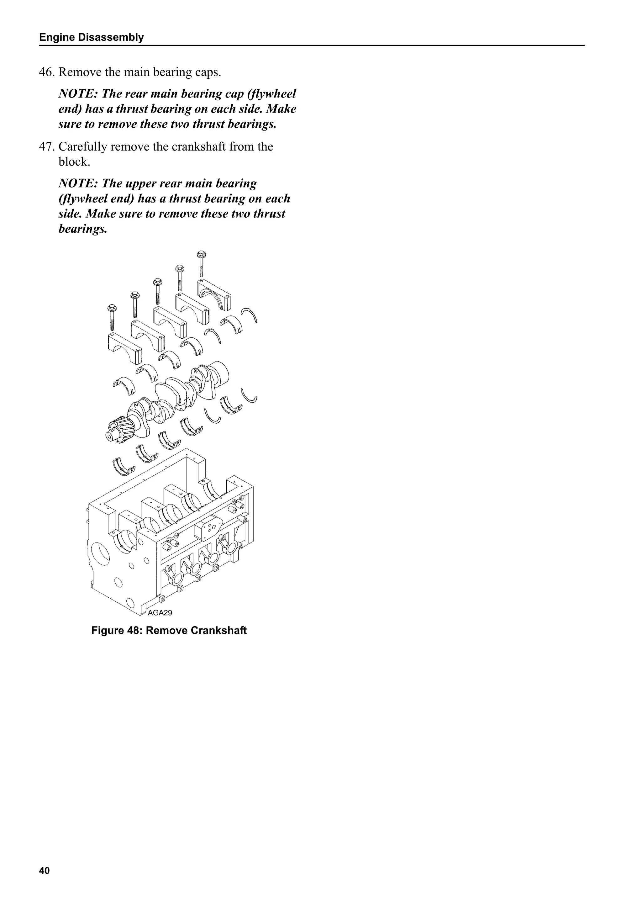
Rocker Arm Shaft Outside Diameter 0.6286-0.6293 in. (15.966-15.984 mm) 0.6280 in. (15.950 mm)
Tier 1 and Earlier -
TK482, TK482E, TK486, TK486E, and TK486EH (Continued)](https://image.slidesharecdn.com/yammarmanualtk486vtk486e1-201015200004/75/Yammar-manual-tk486_v-_tk486e-1-12-2048.jpg)


![17
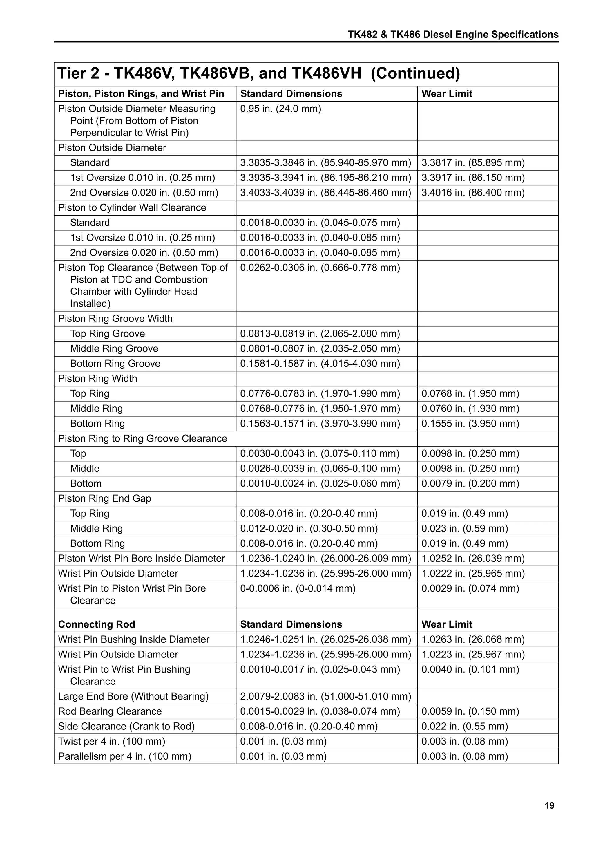
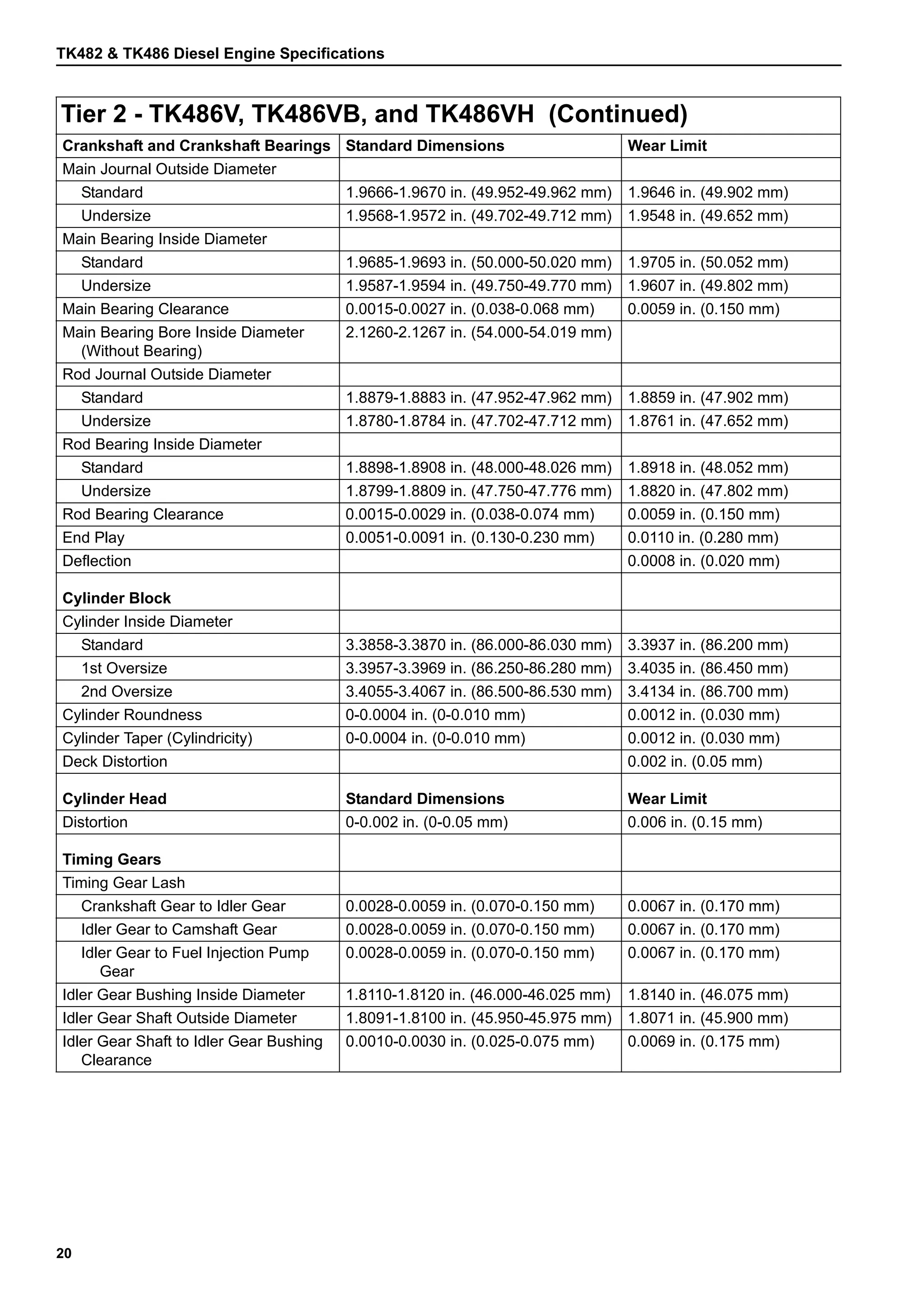
Tier 2 - TK486V, TK486VB, and TK486VH
Except where noted, the specifications for these engines are the same.
General
Type Four Stroke Cycle Water Cooled
Number of Cylinders 4
Cylinder Arrangement In-line Vertical, Number 1 on Flywheel End
Bore 3.39 in. (86.0 mm)
Stroke 3.54 in. (90.0 mm)
Displacement 128 cu. in. (2.09 liters)
Power Rating
TK486V and TK486VB 33.9 hp (25.3 kW) @ 2200 rpm
TK486VH 35.0 hp (26.1 kW) @ 2600 rpm
Compression Ratio 19.1 to 1
Direction of Rotation Counterclockwise (Viewed from Flywheel)
Firing Order 1-3-4-2 (Number 1 on Flywheel End)
Fuel Injection Timing See “Injection Pump Timing Tier 2 Engines” on page 102.
Nozzle Injection Pressure 3,100-3,300 psi (21,600-22,600 kPa)
Oil Pressure 18.5 psi (127 kPa) Minimum @ 230 F (110 C) & 1600 rpm
45-57 psi (310-390 kPa) @ 230 F (110 C) & 2200 rpm
Engine Coolant Thermostat 160 F (71 C)
Valve Clearance (Static @ 70 F [21 C])
Intake 0.006-0.010 in. (0.15-0.25 mm)
Exhaust 0.006-0.010 in. (0.15-0.25 mm)
Valve Train Standard Dimensions Wear Limit
Valve Spring
Free Length 1.65 in. (42.0 mm) 1.63 in. (41.5 mm)
Inclination (Top to Bottom from
Vertical)
0-0.04 in. (0-1.4 mm) 0.06 in. (1.4 mm)
Valve Guide Inside Diameter
Intake 0.3154-0.3159 in. (8.010-8.025 mm) 0.3189 in. (8.100 mm)
Exhaust 0.3156-0.3161 in. (8.015-8.030 mm) 0.3189 in. (8.100 mm)
Valve Stem Outside Diameter
Intake 0.3132-0.3140 in. (7.955-7.975 mm) 0.3110 in. (7.900 mm)
Exhaust 0.3132-0.3138 in. (7.955-7.970 mm) 0.3110 in. (7.900 mm)
Valve Stem to Valve Guide Clearance
Intake 0.0014-0.0028 in. (0.035-0.070 mm) 0.0071 in. (0.180 mm)
Exhaust 0.0018-0.0030 in. (0.045-0.075 mm) 0.0071 in. (0.180 mm)
Valve Margin
Intake 0.053 in. (1.34 mm) 0.020 in. (0.50 mm)
Exhaust 0.057 in. (1.45 mm) 0.020 in. (0.50 mm)](https://image.slidesharecdn.com/yammarmanualtk486vtk486e1-201015200004/75/Yammar-manual-tk486_v-_tk486e-1-17-2048.jpg)


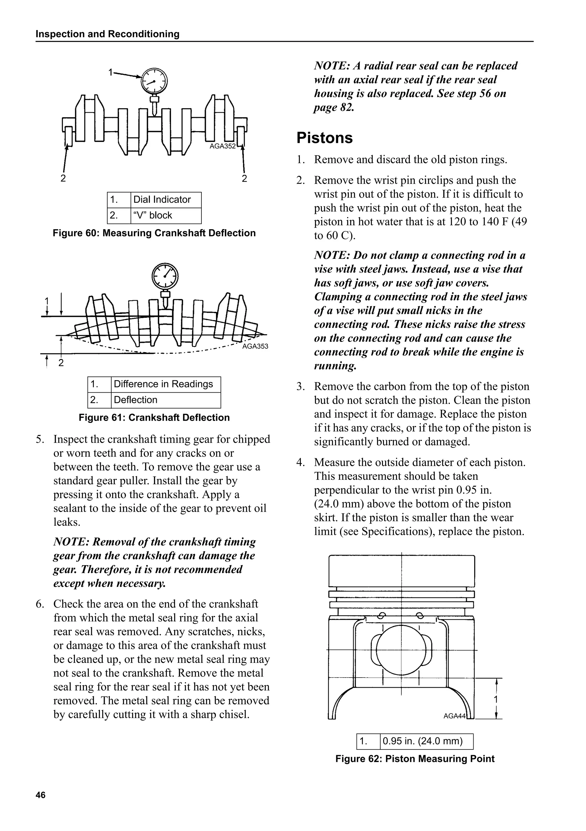

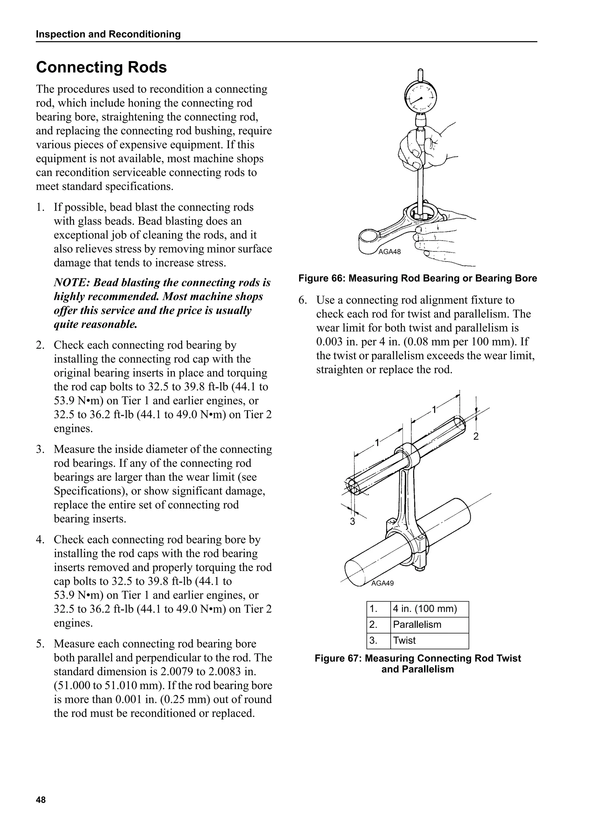


![Inspection and Reconditioning
67
Checking Crankcase Pressure
1. An adapter to check crankcase pressure can be
made from a TK482/486 dipstick (P/N
11-8667) and a fitting (P/N 55-2857).
2. Cut the dipstick off of the cap and cut a
section out of the tab on top of the cap. Make
the section cut out of the tab wide enough to
install the fitting (P/N 55-2857).
3. Drill a 11/32 in. (8.7 mm) hole in the cap. Tap
the hole with an 1/8 in. NPT tap and install the
fitting.
4. This adapter provides a convenient hook-up
for the Magnehelic gauge to monitor
crankcase pressure.
5. To use the adapter, remove the oil dipstick and
replace it with the adapter. Connect the low
pressure side of the Magnehelic gauge (10 in.
[254 mm] minimum) to the adapter and
observe the readings on high and low speed.
1. Fitting
2. Cut Section Out of Tab
3. Dipstick Cap
4. Cut Dipstick Off
Figure 113: Magnehelic Gauge Adapter
1 2 3 4
1. Adapter
2. Magnehelic Gauge
Figure 114: Measuring Crankcase Pressure
1
2](https://image.slidesharecdn.com/yammarmanualtk486vtk486e1-201015200004/75/Yammar-manual-tk486_v-_tk486e-1-67-2048.jpg)


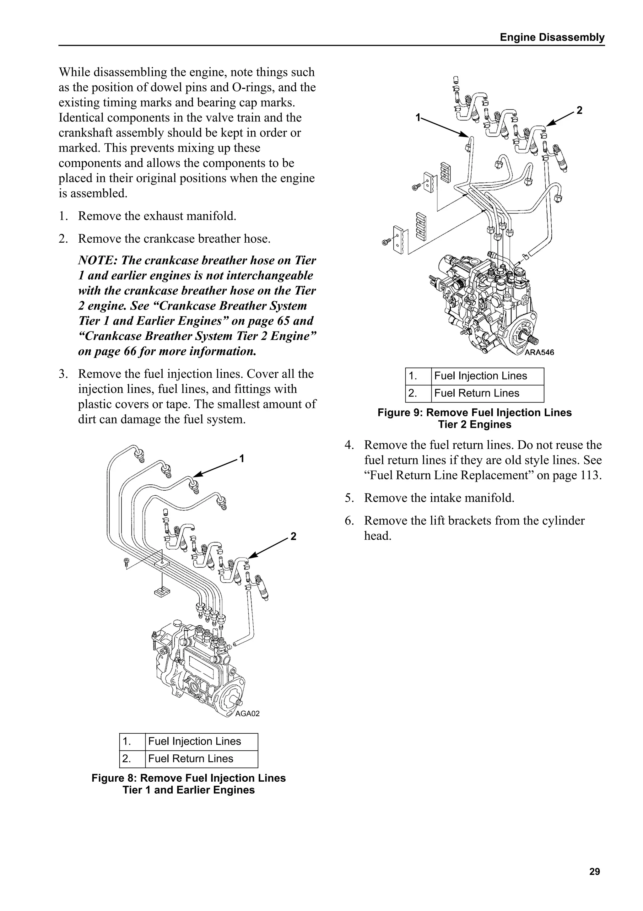
![Fuel System
99
11. Slowly turn the engine in the normal direction
of rotation until you see the fuel rise in the end
of the delivery valve holder. Stop as soon as
you see the fuel rise slowly.
12. Check position of the timing marks.
a. On TK482 and TK486 engines the
injection timing mark on the flywheel
should be aligned with the index mark on
the side of the timing mark access hole.
b. On TK482E and TK468E engines the 10
degree BTDC timing mark on the flywheel
should be aligned with the index mark on
the side of the timing mark access hole.
c. On TK486EH engines the index mark
should align with the midpoint between
the two timing marks on the flywheel.
13. Repeat steps 8 through 12 to recheck the
timing.
14. If the timing is off by more than 1 degree (0.1
in. [2.5 mm]), loosen the mounting nuts on the
studs that fasten the injection pump to the
engine and rotate the injection pump to change
the timing.
a. Pull the top of the injection pump away
from the engine to advance the timing.
b. Push the top of the injection pump toward
the engine to retard the timing.
15. Tighten the injection pump mounting nuts and
recheck the timing. Repeat steps 8 through 15
until the timing is correct.
16. Install the cover in the timing mark access
hole, install the injection line for the number
one cylinder, tighten the other injection lines,
and reconnect the 8S wire to the starter
solenoid when finished with the procedure.
1. Index Mark
2. Injection Mark
Figure 188: Correct Timing Mark Alignment
for TK482 and TK486
1. Index Mark
2. 12 Degree BTDC Timing Mark
3. 10 Degree BTDC Timing Mark
Figure 189: Correct Timing Mark Alignment
for TK482E and TK468E
AEA703
1 2
1 2
3
1. Index Mark
2. 12 Degree BTDC Timing Mark
3. 10 Degree BTDC Timing Mark
Figure 190: Correct Timing Mark Alignment
for TK486EH
1
2
3](https://image.slidesharecdn.com/yammarmanualtk486vtk486e1-201015200004/75/Yammar-manual-tk486_v-_tk486e-1-99-2048.jpg)


![Fuel System
121
Static Air Leaks Tier 1 and Earlier
Engines
There are two places where air can leak into the
static fuel system:
• One is the through the plungers in the
injection pump. It leaks from the pump
camshaft and lifter area around the plungers
and into the fuel galley in the pump. Over the
years the plunger clearances have been
reduced to try to prevent air leaks.
• The other is anywhere else.
If air is leaking through the plungers the engine
will not start, not even try to fire because the air is
in the injection pump.
If the air is getting in anywhere else, it will end up
in the fuel filter and the engine will start, run for a
few seconds, and then die. In this case you may
see an Alarm Code 63 on a unit with a
microprocessor.
Solution for Static Air Leaks
Understanding the problem helped find a solution.
The vacuum cannot be stopped from forming in
return line. The air leakage at the injection pump
plungers can be minimized, but not stopped. The
solution was to stop the vacuum from forming in
the whole system by moving the 5-psi (34-kPa)
relief valve from the outlet of the injection pump
to the return fuel outlet in the fuel filter head.
NOTE: Even though it is often called a check
valve, it functions as a relief valve, not a check
valve. A check valve would close when return
fuel tried to go to the tank. This functions a 5-psi
(34-kPa) relief valve. When the return fuel
pressure reaches 3 to 5 psi (21 to 34 kPa), the
spring in the relief valve allows the piston to
retract, which allows the return fuel to flow back
to the fuel tank. When the engine stops, the
spring pushes the piston closed and traps a
positive pressure in the fuel system. The relief
valve is not always a perfect seal, but as the
pressure side drops from leakage, the spring
pushes the piston closed tighter. By the time the
pressure reaches zero, the piston is usually
completely sealed.
This relief valve has been installed on production
units since 1999 and many units have been
retrofitted with kit P/N 10-342.
This solution provides a positive way to keep
5 psi (34 kPa) in the injection pump when the
engine is running to answer Yanmar's
requirement, and prevents a vacuum from forming
in the fuel system when the engine is off.
NOTE: You must remove the original Yanmar
relief valve from the injection pump when
installing kit P/N 10-342. If not, it will take a
pressure of at least 10 psi (69 kPa) to overcome
the relief valves. This will make it much harder
to prime the system with the hand pump.
FAQ (Frequently Asked Questions)
If the unit is leaking air when it’s off, why
doesn't it leak fuel when it runs?
It is probably a matter of time and size. Most of
the hard starting problems caused by air take a
long engine off period, usually days or weeks,
indicating they are extremely small. It could be
that the fuel boils off a warm engine before it is
even seen.
Why can't I find the leaks when I pressurize
the fuel system?
Again, it is time and size. If you pressurize the
fuel tank, do not go over 5 to 10 psi (34 to 69
kPa). Never pressurize a fuel system without a
relief valve in the supply regulator set at 10 psi
[69 kPa] maximum. A leak that pulls in 50 cc of
air in a week (enough to affect starting) is going to
take hours or days to show under pressure.
How can I check the fuel return relief valve?
Probably the quickest way is to replace it. If that
fixes it, then that was the problem. If not, it means
it is something else, or you have another faulty
relief valve.
The only sure way of checking a relief valve is to
take a clear hose at least 8 ft (2.4 m) long and
immerse it in water or fuel. Make sure the hose
fills completely with liquid. Keep the hose
immersed and insert the outlet end of the valve
into the hose. Slowly raise the valve out of the
liquid with the hose following it. The liquid
should not drop out of the hose. Raise the valve
8 ft (2.4 m) in the air and keep the other end of the](https://image.slidesharecdn.com/yammarmanualtk486vtk486e1-201015200004/75/Yammar-manual-tk486_v-_tk486e-1-121-2048.jpg)


![Electrical
134
During the time the fuel solenoid relay is
momentarily energized, the fuel solenoid pull-in
coil is energized by the 2A circuit through the
normally open contacts of the fuel solenoid relay
and the 8DP circuit.
When power is removed from the 8D circuit the
fuel solenoid hold-in coil is de-energized, and the
fuel solenoid resets.
Troubleshooting the Fuel Solenoid Timer
System
NOTE: The fuel solenoid pull-in coil will
require 35 to 45 amps to turn on the fuel. The
unit’s battery must be in good condition. If the
battery has enough power to crank the engine
over, it has enough power to energize the fuel
solenoid pull-in coil.
If you suspect that the engine does not run
because the fuel solenoid is not operating
correctly, use the following procedure:
1. Disconnect the fuel solenoid wire connector
from the main wire harness.
2. Turn the unit on to energize the fuel solenoid
circuits. If the unit has a microprocessor, use
the microprocessor keypad to enter the Relay
Board Test Mode. Energize the fuel solenoid
circuits by energizing the run relay [RUNR]
with the Relay Board Test Mode.
3. Check the voltage on the 8D circuit (pin A) in
the main wire harness connector for the fuel
solenoid. Refer to the following illustrations
to identify the pins in the wire connectors.
a. If battery voltage is not present on the 8D
circuit, check the 8D circuit and the
related circuits and components for a fault.
b. If battery voltage is present on the 8D
circuit, go to step 4.
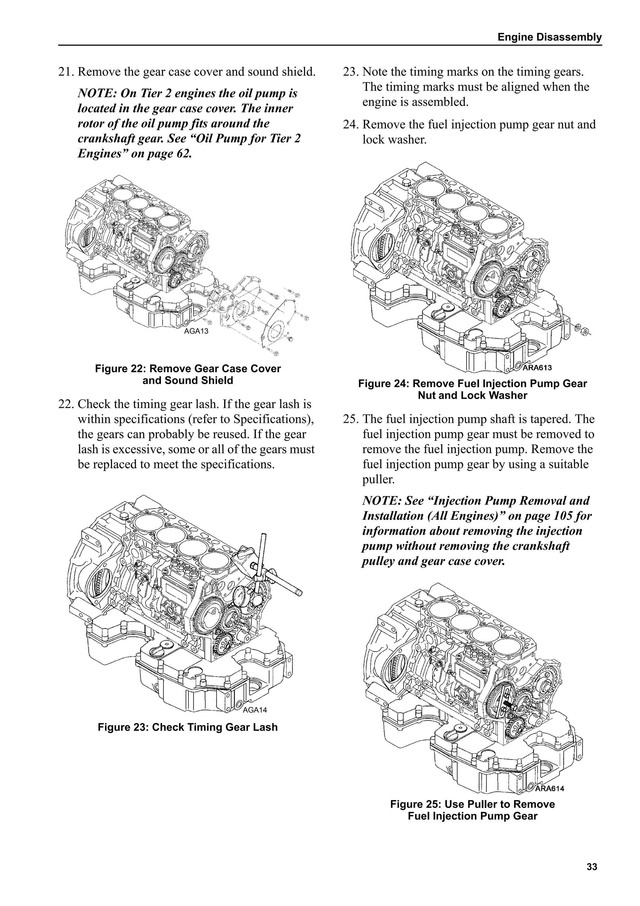
Figure 263: Main Wire Harness
Connector Pin Identification
4. Check the CH circuit (pin C) in the main wire
harness connector for continuity to a good
chassis ground.
a. If there is no continuity between the CH
circuit and a good chassis ground, check
the CH wire for an open circuit.
b. If there is continuity between the CH
circuit in the main wire harness at the fuel
solenoid wire connector and a good
chassis ground, go to step 5.
1. Fuel Solenoid Relay Contacts
2. Fuel Solenoid Pull-In Coil
3. Fuel Solenoid Hold-In Coil
4. Fuel Solenoid Timer
5. Fuel Solenoid Relay Coil
Figure 262: Simplified Schematic Diagram
of Fuel Solenoid System
1
2
3
45
AGA310
1. Red (8D)
2. White (8DP)
3. Black (CH)
Figure 264: Fuel Solenoid
Connector Pin Identification
AEA704
AEA633](https://image.slidesharecdn.com/yammarmanualtk486vtk486e1-201015200004/75/Yammar-manual-tk486_v-_tk486e-1-134-2048.jpg)
![Electrical
135
5. Place a jumper wire between the black wire
(CH—pin C) in the fuel solenoid connector
and a good chassis ground.
6. Test the pull-in coil by momentarily placing a
jumper between the white wire (8DP—pin B)
in the fuel solenoid connector and the positive
battery terminal. The fuel solenoid should
make a definite click when the pull-in coil is
energized and should click again when the
pull-in coil is de-energized.
NOTE: The pull-in coil will draw 35 to 45
amps so do not leave the jumper connected to
the white wire (8DP—pin B) for more than a
few seconds.
a. If the pull-in coil does not energize, check
the resistance of the pull-in coil by placing
an ohmmeter between the white wire
(8DP—pin B) and the black wire (CH—
pin C) in the fuel solenoid connector. The
resistance of the pull-in coil should be 0.2
to 0.3 ohms. If the resistance of the pull-in
coil is not in this range, replace the fuel
solenoid.
NOTE: If the pull-in coil fails, make sure to
replace the fuel solenoid relay with relay
P/N 41-893. This particular relay is needed
for the high current flow through the hold-in
coil.
b. If the pull-in coil does energize, go to
step 7.
7. Test the hold-in coil.
a. Energize the hold-in coil by placing a
jumper between the red wire (8D—pin A)
in the fuel solenoid connector and the
positive battery terminal.
b. Momentarily energize the pull-in coil by
placing a jumper between the white wire
(8DP—pin B) in the fuel solenoid
connector and the positive battery
terminal. The fuel solenoid should make a
definite click when the pull-in coil is
energized, but should not click when the
pull-in coil is de-energized.
c. De-energize the hold-in coil by removing
the jumper from the red wire (8D—pin A)
and the positive battery terminal. The fuel
solenoid should make a definite click
when the hold-in coil is de-energized.
d. If the hold-in coil does not function
properly, check the resistance of the
hold-in coil by placing an ohmmeter
between the red wire (8D—pin A) and the
black wire (CH—pin C) in the fuel
solenoid connector. The resistance of the
hold-in coil should be 24 to 29 ohms. If
the resistance of the hold-in coil is not in
this range, replace the fuel solenoid.
e. If the hold-in coil does function properly,
go to step 8.
8. Reconnect the fuel solenoid connector and the
main wire harness connector.
9. Remove the fuel solenoid relay from its socket
and make sure the unit is turned on, and is in
the Relay Board Test Mode [RUNR] if it has a
microprocessor.
10. Check the voltage on the 8D circuit at the 86
terminal in the fuel solenoid relay socket.
Refer to the following illustration to identify
the terminals in the relay socket.
a. If battery voltage is not present on the 8D
circuit, check the 8D circuit and the
related circuits and components for a fault
(minimum voltage is 10 volts).
b. If battery voltage is present on the 8D
circuit, go to step 11.
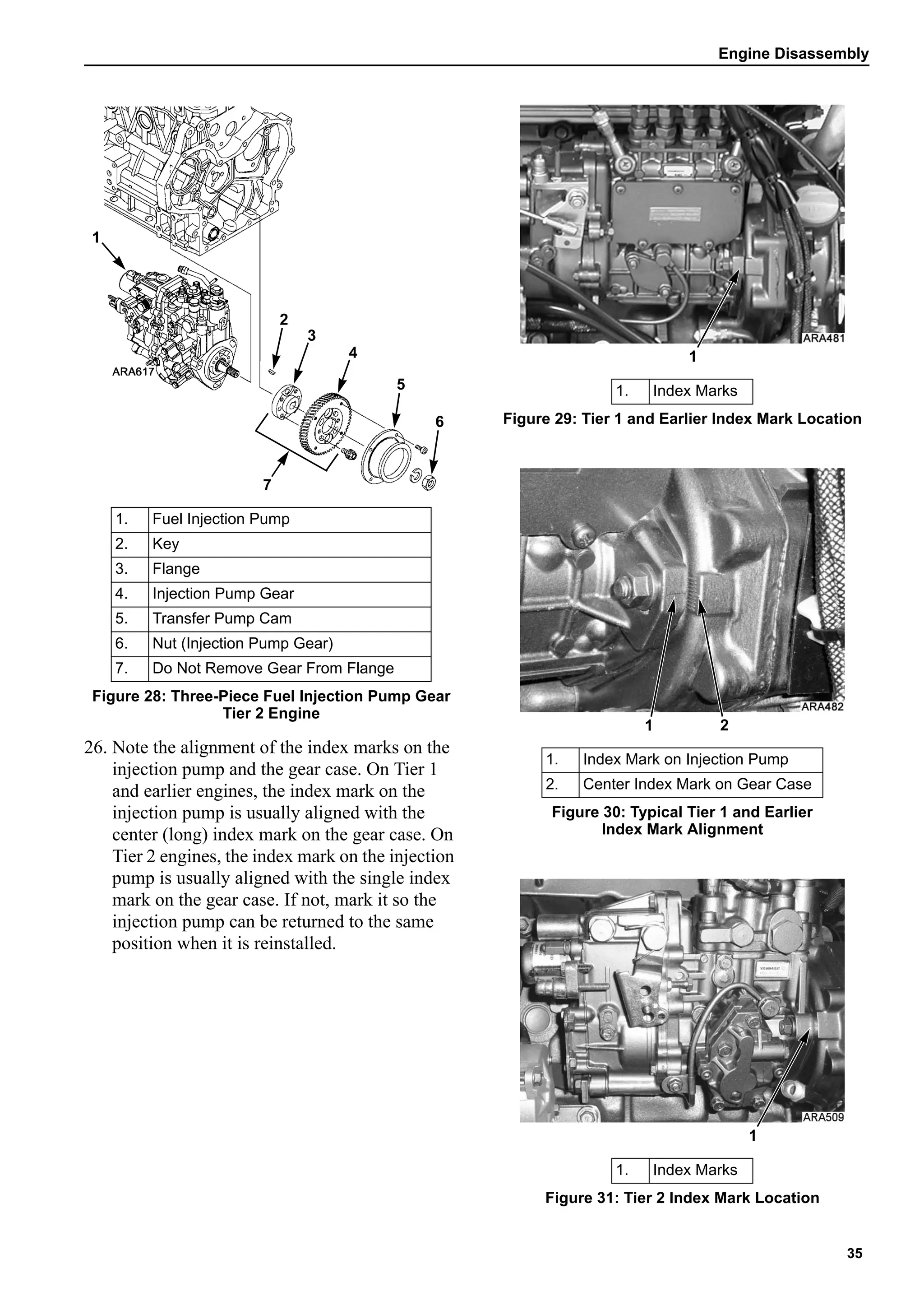
1. 30 Terminal—2A Circuit
2. 86 Terminal—8D Wire
3. 87 Terminal—8DP Wire
4. 85 Terminal to Capacitor and Diode
Figure 265: Relay Socket Terminal Identification
1 2
34](https://image.slidesharecdn.com/yammarmanualtk486vtk486e1-201015200004/75/Yammar-manual-tk486_v-_tk486e-1-135-2048.jpg)


![Caterpillar Diesel Engine Control Systems [PDF, ENG, 588 KB].en.pt.pdf](https://cdn.slidesharecdn.com/ss_thumbnails/caterpillardieselenginecontrolsystemspdfeng588kb-220908204323-0fe1f161-thumbnail.jpg?width=640&height=640&fit=bounds)


