Downloaded 268 times


![Definition “software”
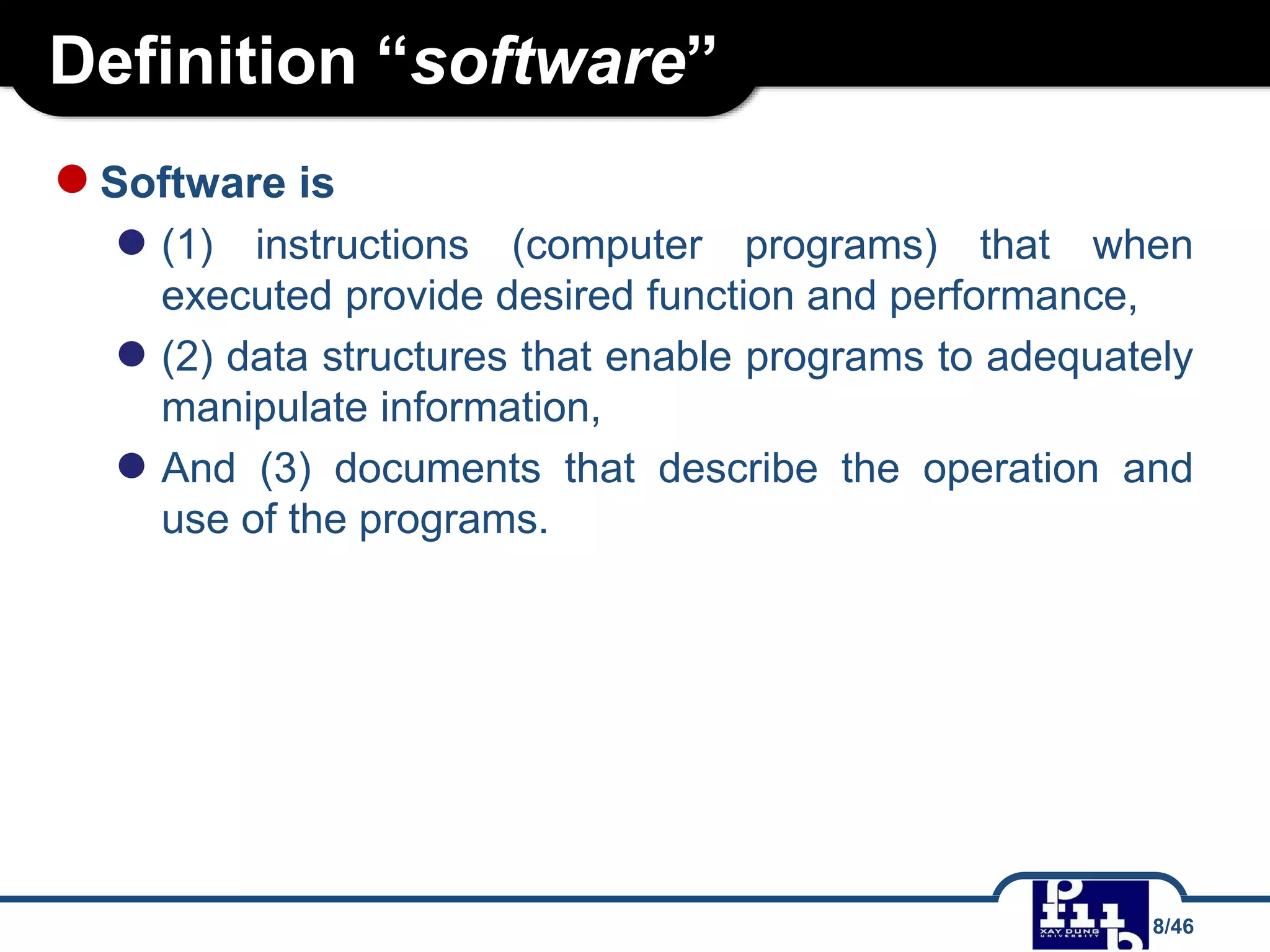
● Software is a collection of instructions that can be ‘run’ on a
computer. These instructions tell the computer what to do. 1
● “Computer software, or simply software, refers to the non-
tangible components of computers, known as computer
programs. The term is used to contrast with computer
hardware, which denotes the physical tangible components of
computers.” [Wikipedia]
(1) http://www.igcseict.info/theory/1/hwsw/
7/46](https://image.slidesharecdn.com/cnpm-200608110223/75/Slides-mon-Cong-ngh-ph-n-m-m-Software-Engineering-7-2048.jpg)


![Definition SE
●Definition proposed by Fritz Bauer
● “[Software engineering is] the establishment and use of
sound engineering principles in order to obtain economically
software that is reliable and works efficiently on real
machines.”
●Definition developed by IEEE
● “Software Engineering: (1) The application of a systematic,
disciplined, quantifiable approach to the development,
operation, and maintenance of software; that is, the
application of engineering to software. (2) The study of
approaches as in (1).”
19/46](https://image.slidesharecdn.com/cnpm-200608110223/75/Slides-mon-Cong-ngh-ph-n-m-m-Software-Engineering-19-2048.jpg)
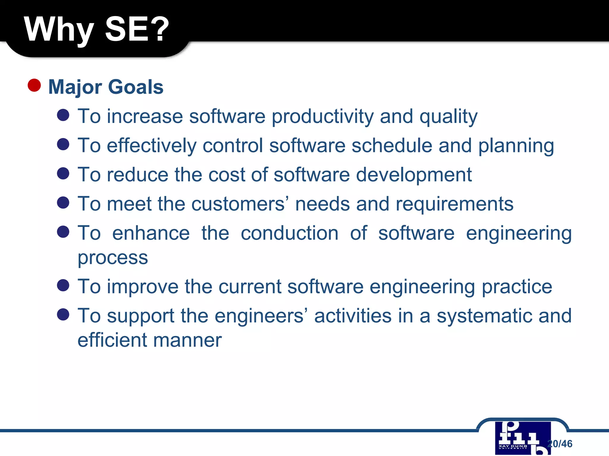


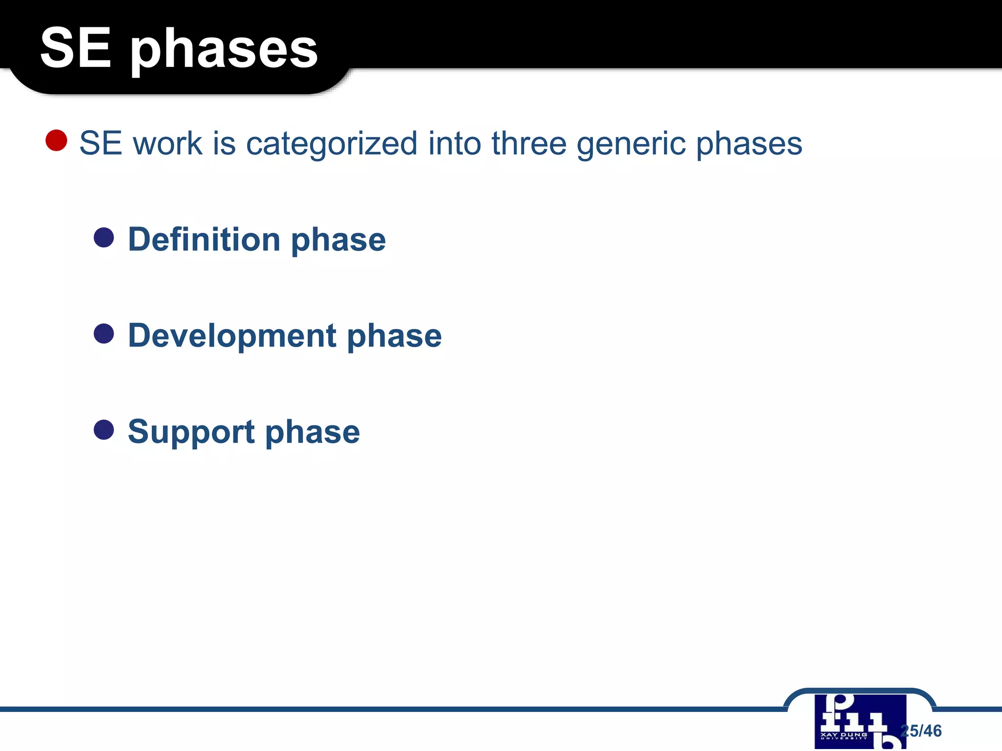
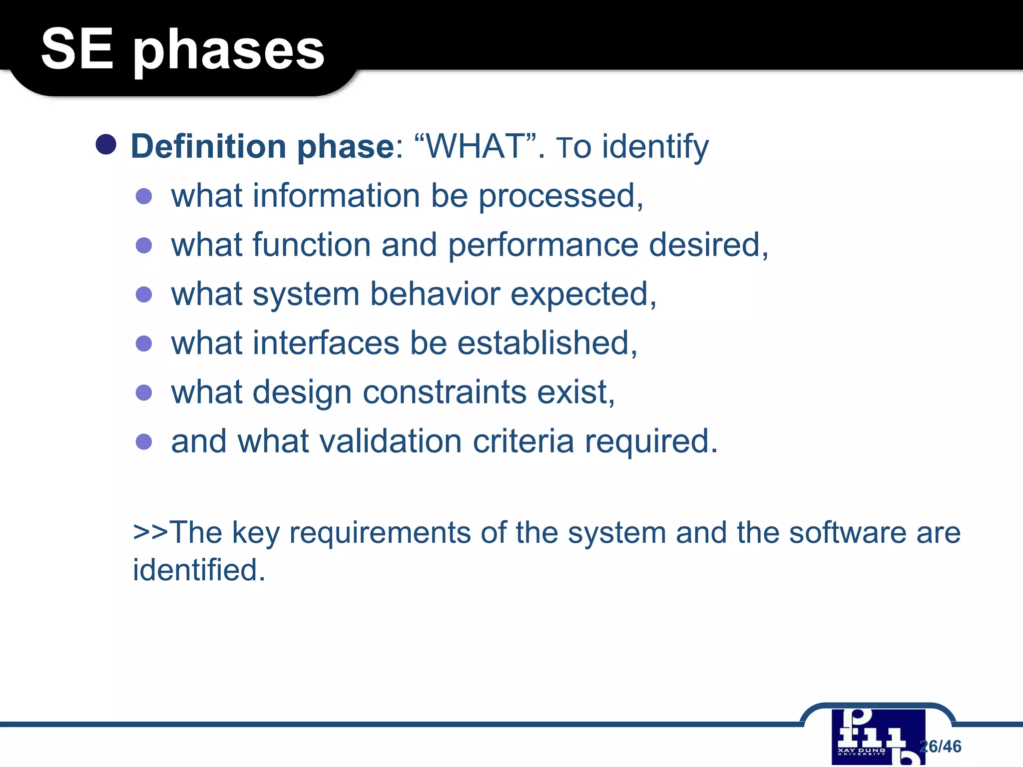


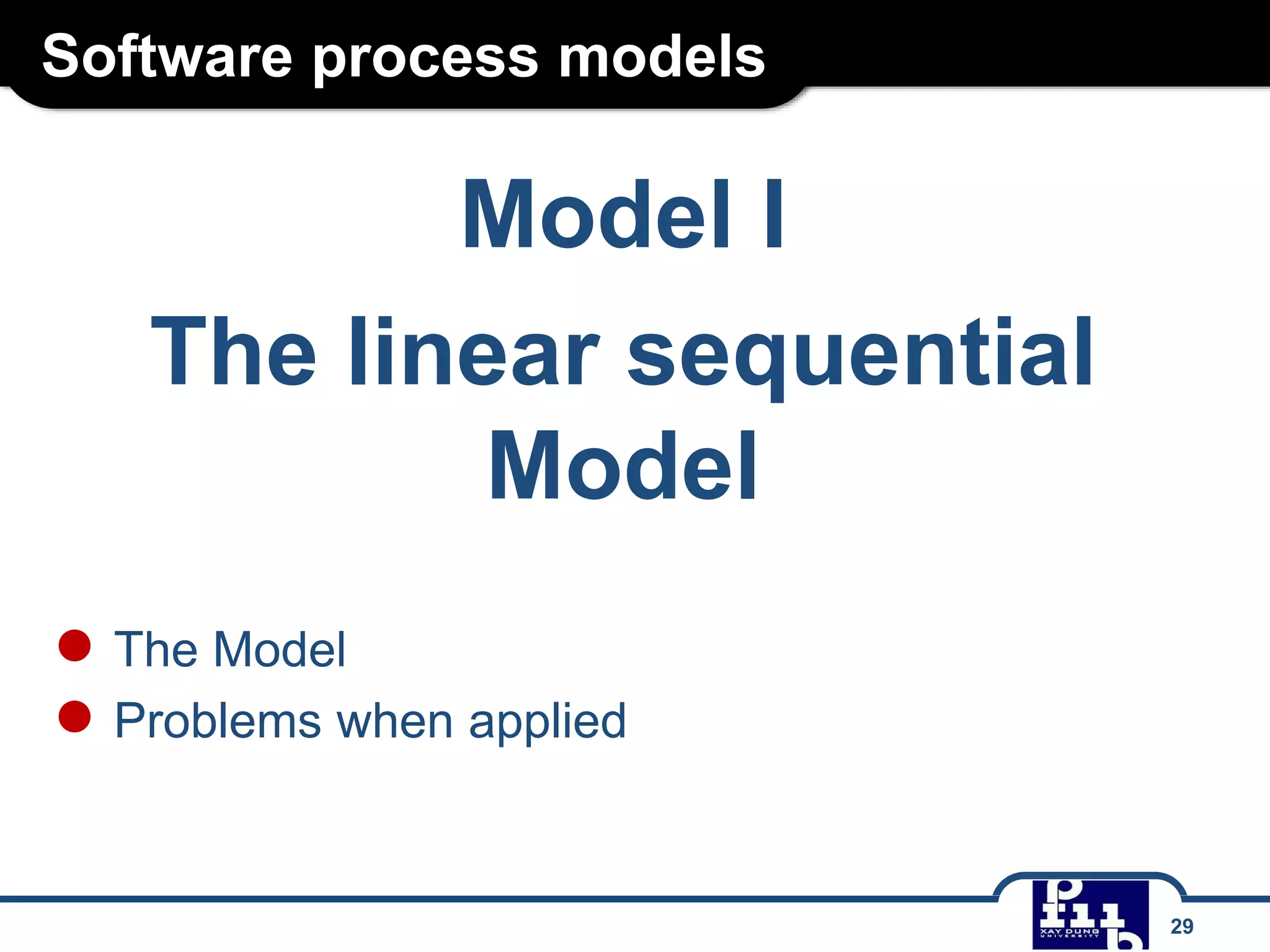


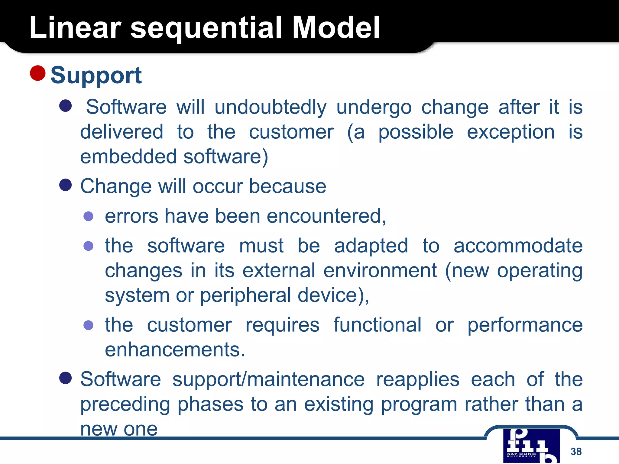


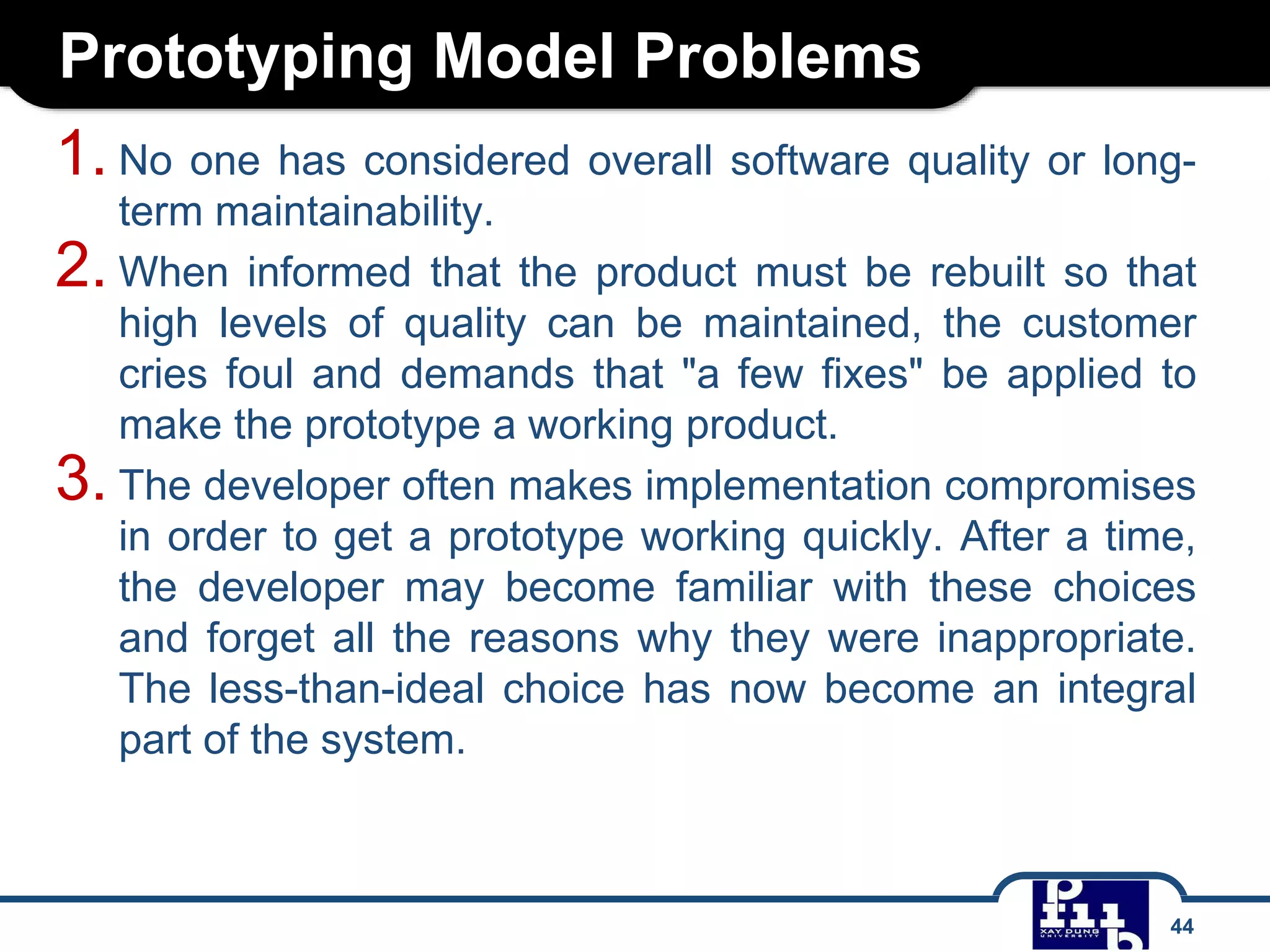


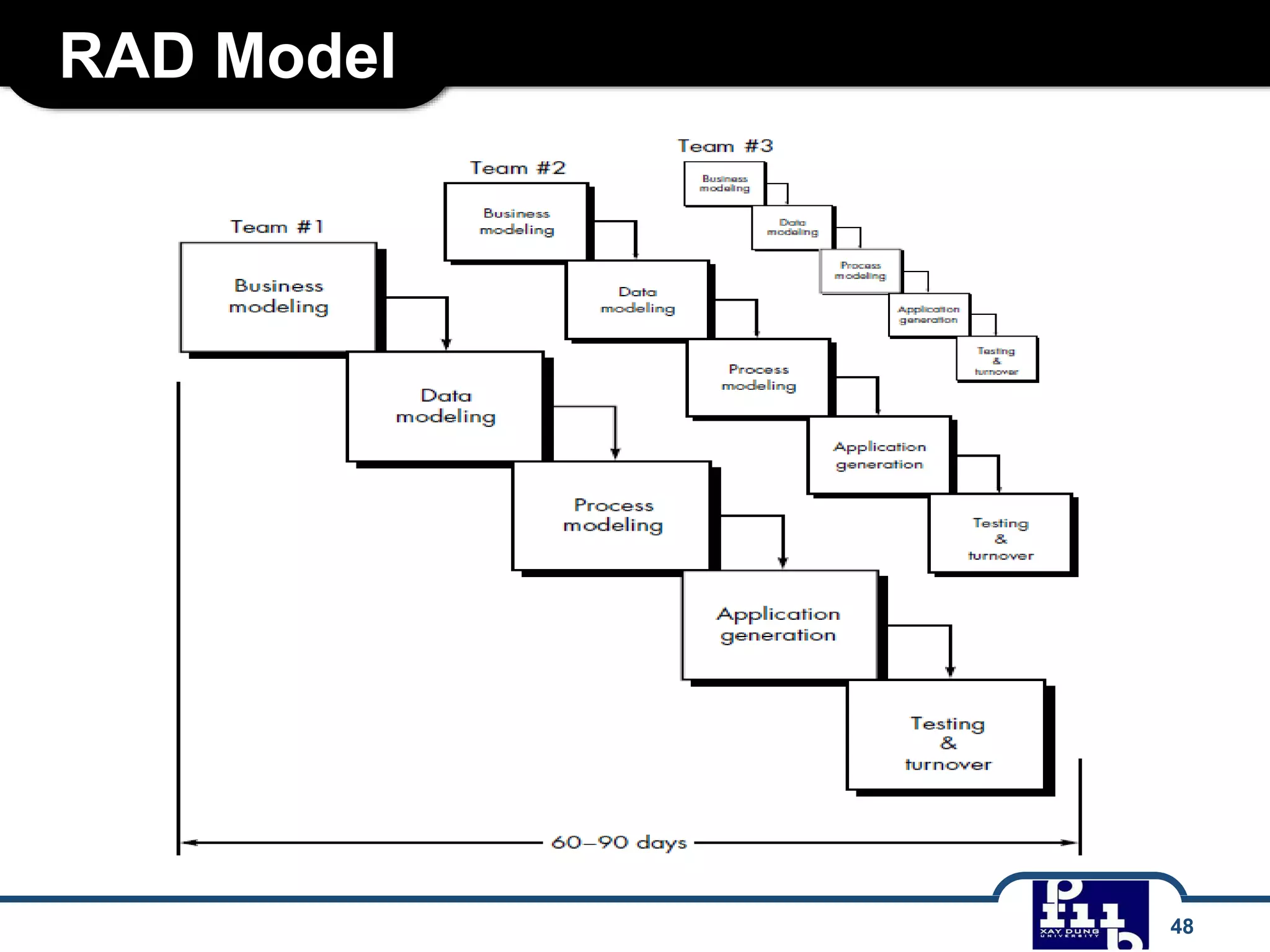


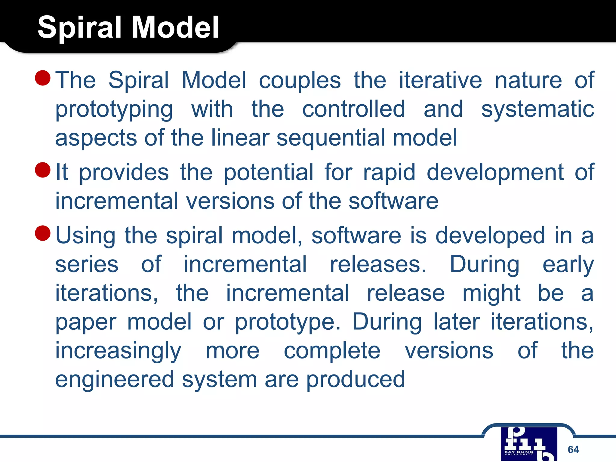


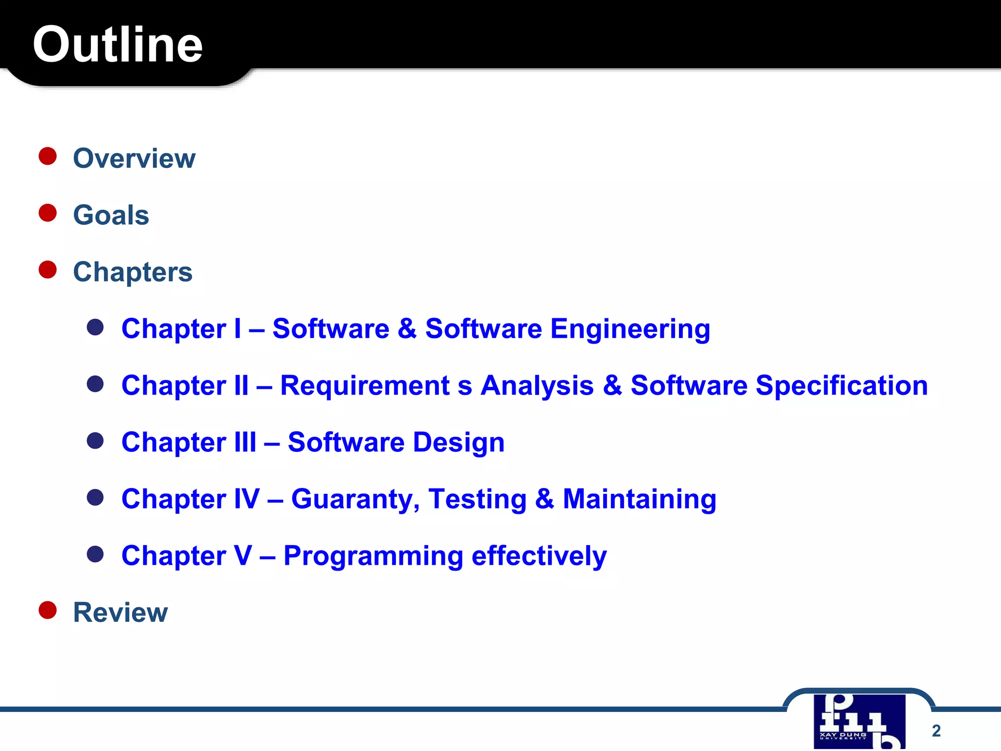
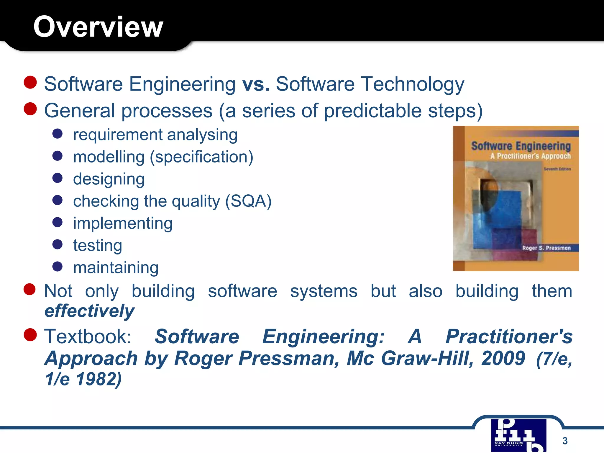
This document provides an overview of software engineering and outlines several key chapters that will be covered. It discusses software engineering as a systematic approach to software development that includes requirements analysis, modeling, design, quality assurance, implementation, testing, and maintenance. Several software process models are also summarized, including the linear sequential model, prototyping model, and RAD (rapid application development) model. The challenges of software development and goals of taking an engineering approach are also mentioned.


![Automata slide DHBKHCM [S2NUCE.blogspot.com]](https://cdn.slidesharecdn.com/ss_thumbnails/automataslidev1-140909095602-phpapp02-thumbnail.jpg?width=640&height=640&fit=bounds)