Download to read offline

![3RW Soft Starters
3RW44
for High-Feature applications
6/25Siemens LV 1 News · 04/2006
66
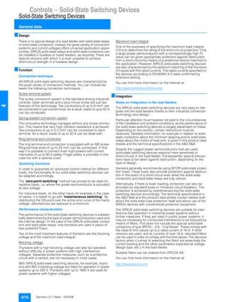
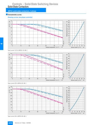
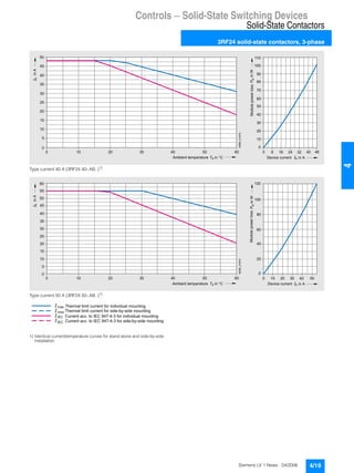
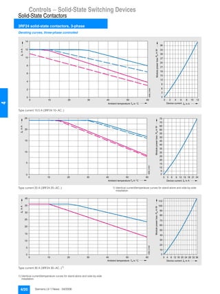
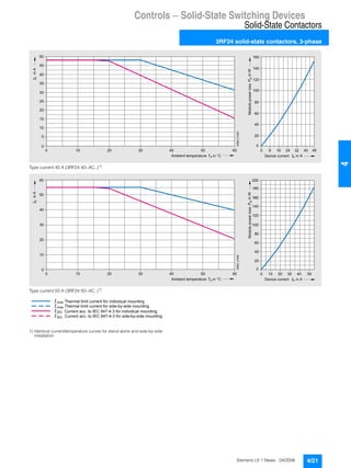
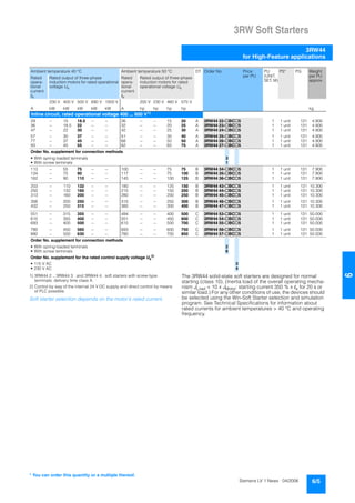
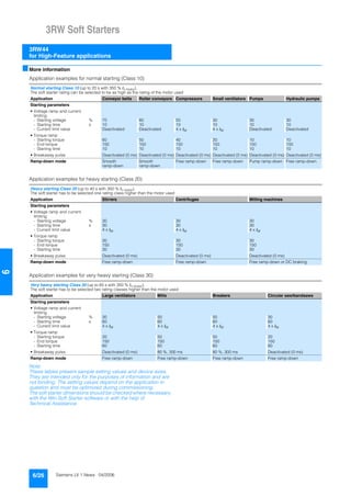
■Characteristic curves
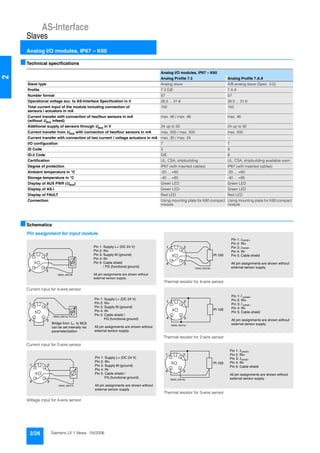
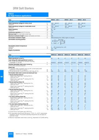
Motor protection tripping characteristics for 3RW44
(with symmetry)
e
2 4 6 101
Class 10 Class 15 Class 20
100
101
102
103
2
4
6
2
4
6
2
4
6
Class 5 Class 30
NSB0_01500
[s]
x
Trippingtime](https://image.slidesharecdn.com/catalogue-siemens-3rf3rwlv12006-160419075603/85/Catalogue-siemens-3-rf-3rw_lv1-2006-87-320.jpg)
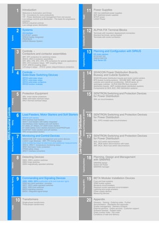
This document provides an overview of Siemens' low-voltage controls and distribution product catalog, including: 1. An introduction to Siemens' automation and drives solutions including TIA and TIP innovations. 2. A listing of the main product sections within the catalog, including systems, controls, protection equipment, monitoring devices, and transformers. 3. Information about related catalogs, technical assistance resources, and the companies quality management system certifications.