Download as PDF, PPTX


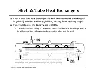


This document provides an overview of shell and tube heat exchanger design. It discusses key elements of shell and tube heat exchangers including types of shells, tube layouts, baffle designs, tube materials, and basic sizing calculations. The document outlines the basic design procedure which involves identifying the problem, selecting an exchanger type, calculating initial parameters, evaluating performance and cost, and iterating the design as needed.


