Download to read offline
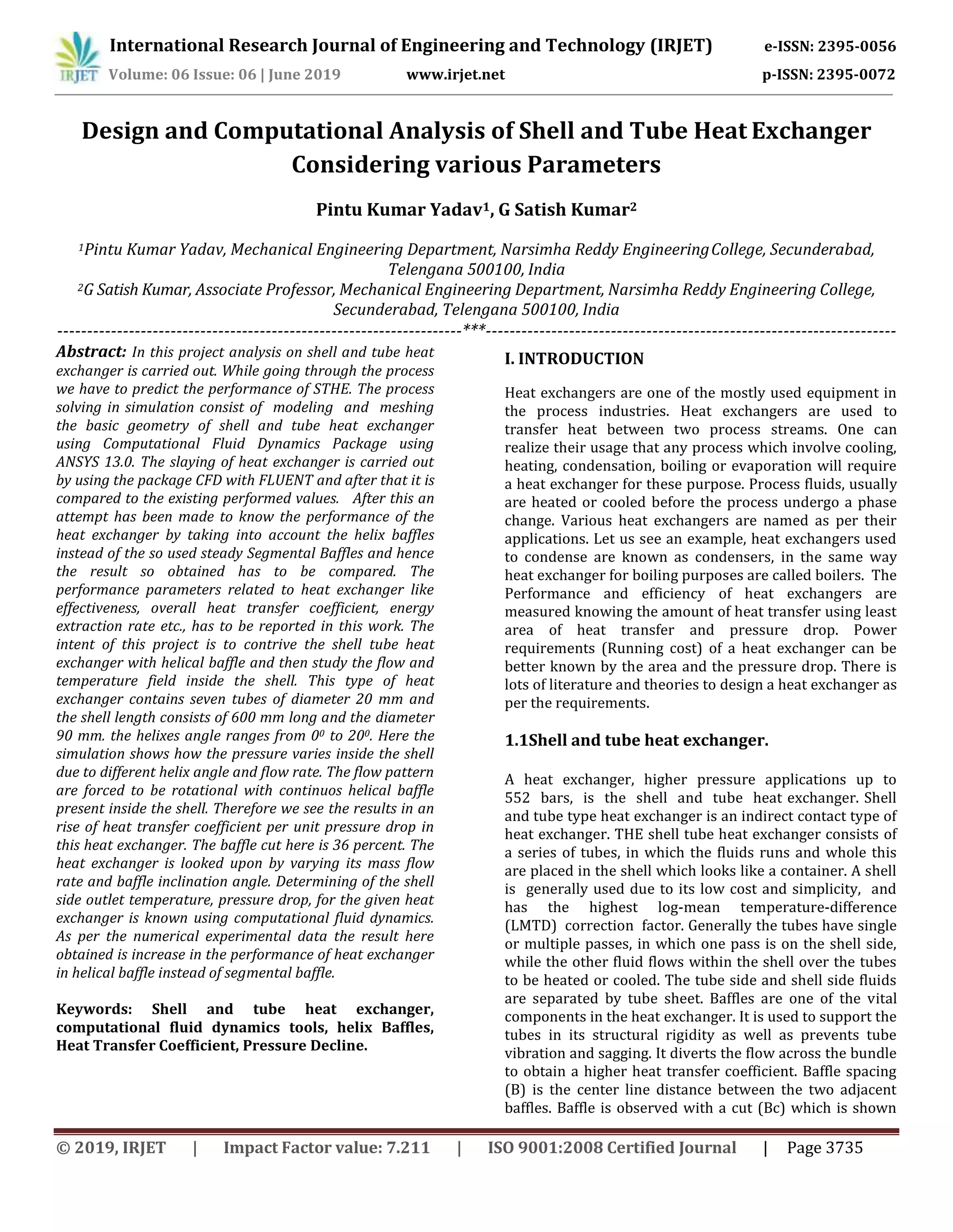
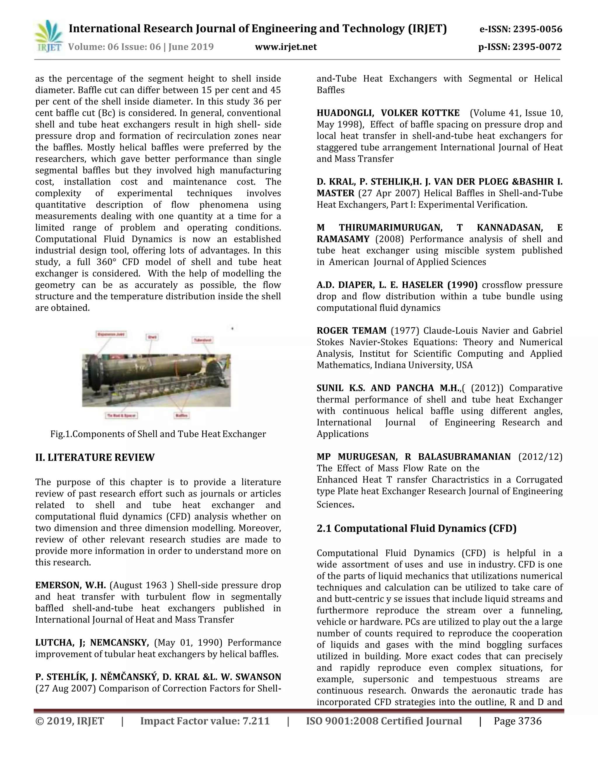
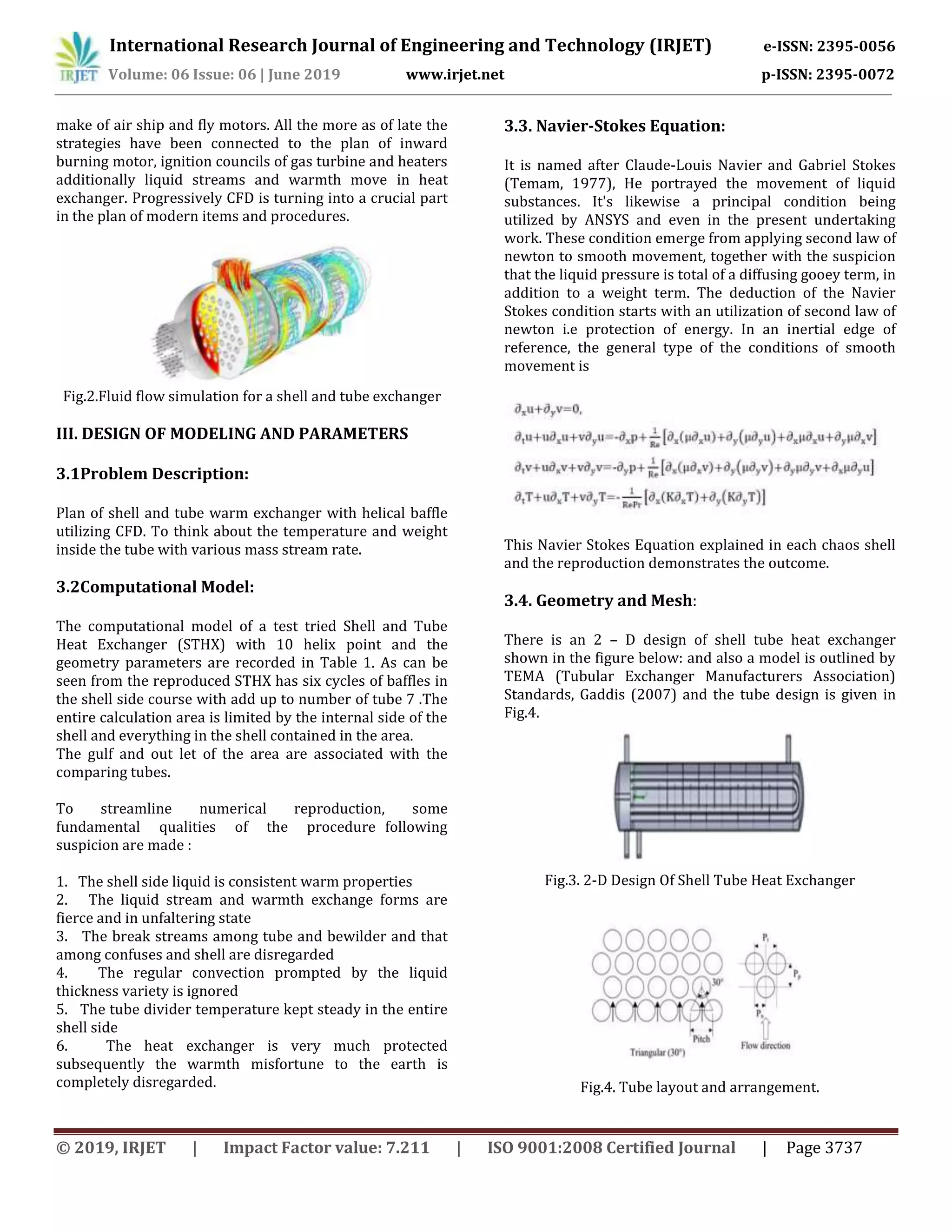
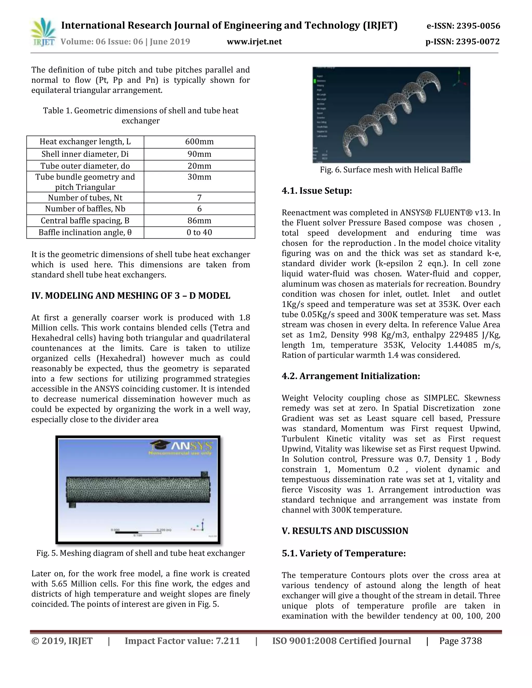
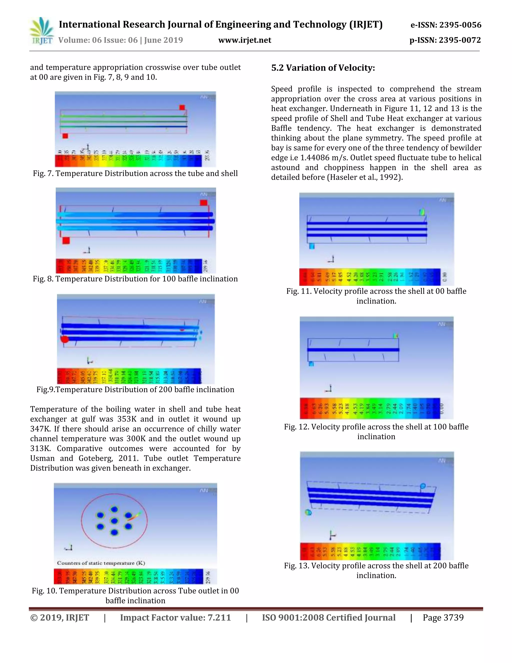
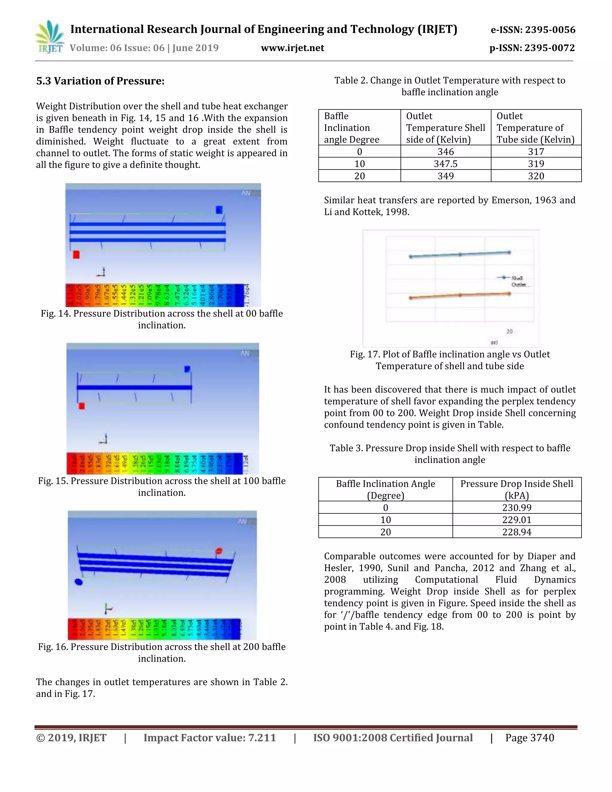
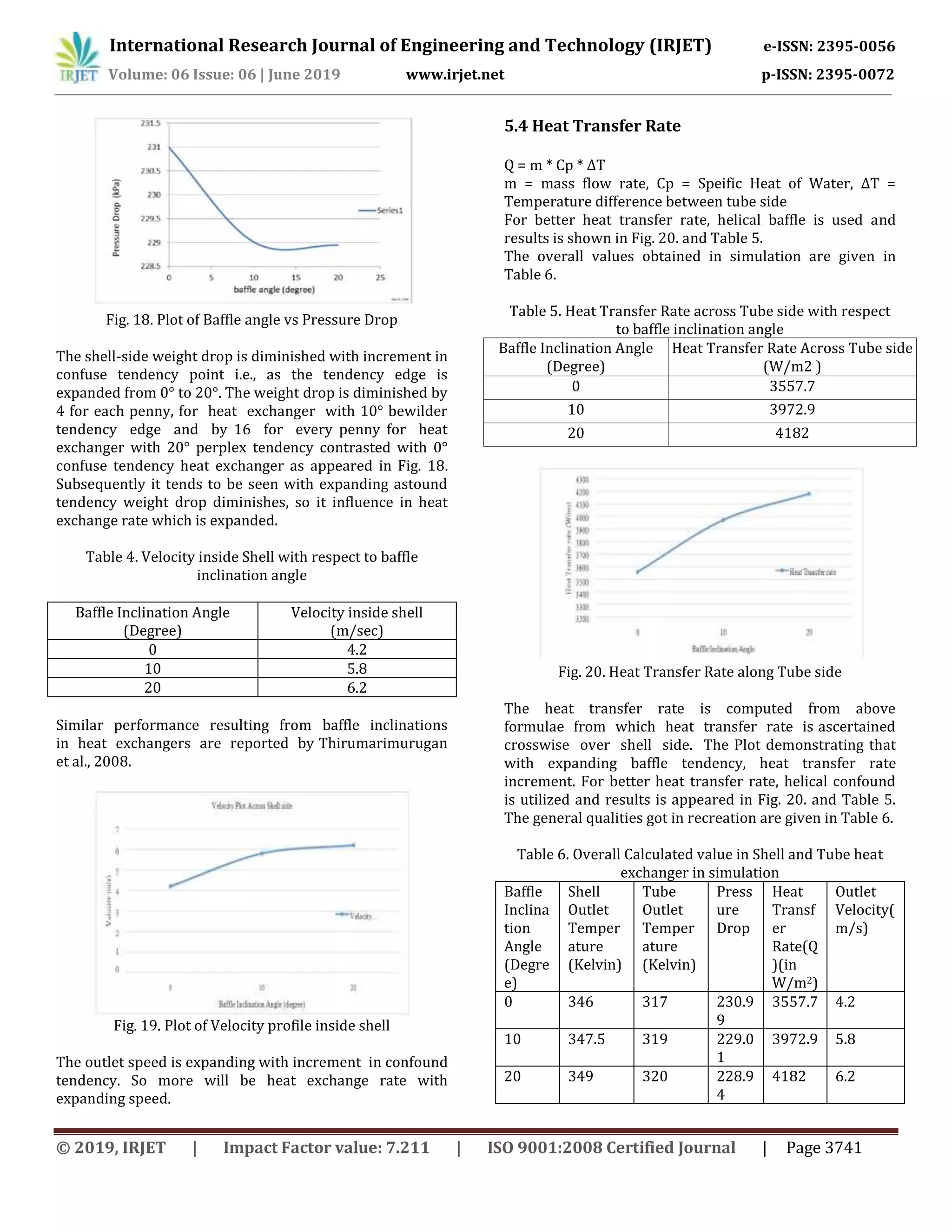

This document describes a computational fluid dynamics (CFD) analysis of a shell and tube heat exchanger considering various parameters. The analysis models and simulates the geometry of a shell and tube heat exchanger using ANSYS to study the temperature and pressure fields inside the shell. Variables analyzed include mass flow rate, baffle inclination angle, outlet temperature, and pressure drop. The results show increased heat exchanger performance with a helical baffle design compared to a conventional segmental baffle design.


