Serial Communication
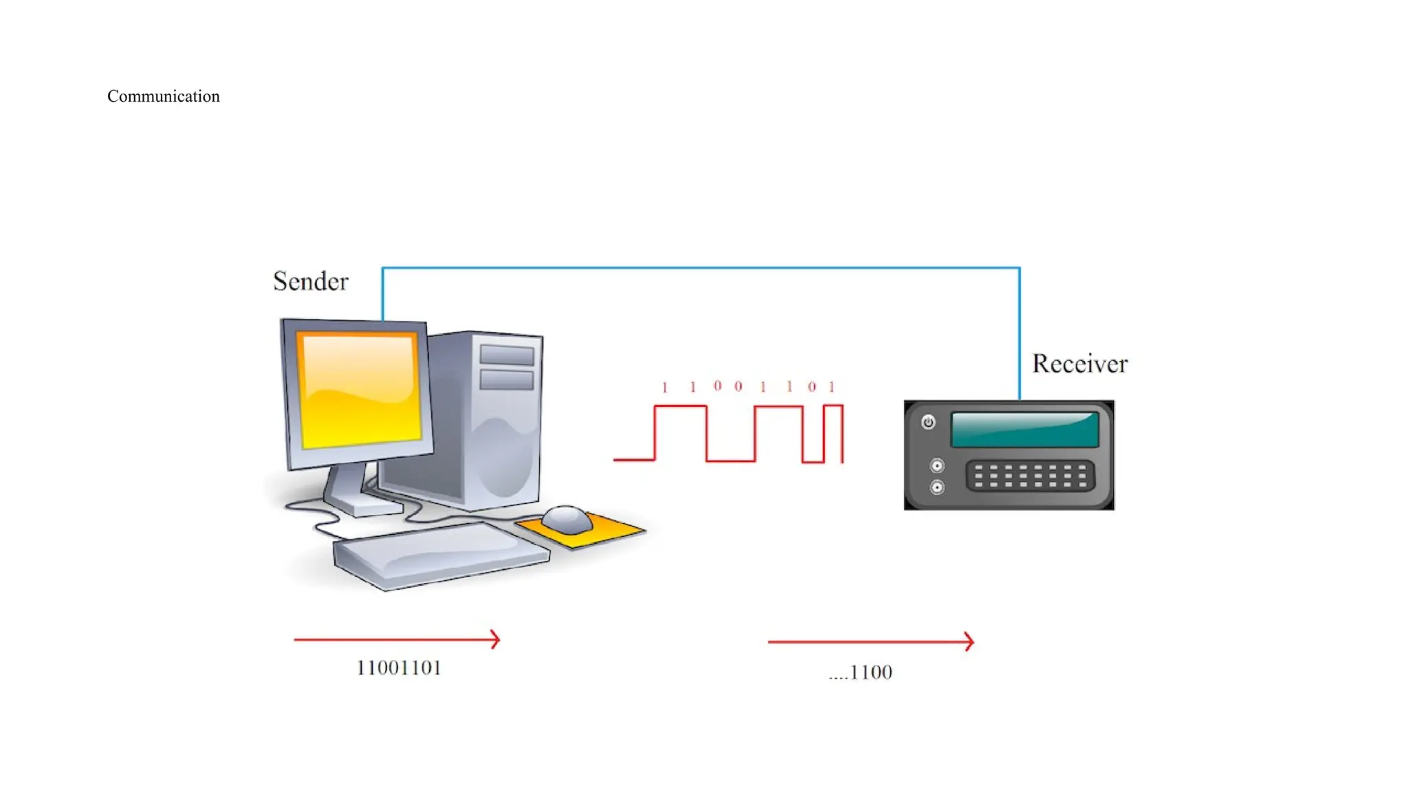
• Communicationis exchange of information between two devices.
• The information is data which can be anything like text documents, images, audio
or video files etc.
• Data can be sent or received between two systems or devices and it is in the form
of bits i.e. 0’s and 1’s.
• There are many types of protocols that are used in transferring data between two
devices, but all these protocols are based on either Parallel Communication or
Serial Communication.
4.
Parallel Vs Serialcommunication
• Parallel communication is a method of transferring multiple bits of data simultaneously using high-speed
number of data lines.
• Example: Old printers and hard disks. parallel communication increases the speed of data transmission by
using separate channel for each bit to be transmitted. (RAM in modern computers)
• The high-speed data transfers in parallel communication requires more number of wires and also the distance
of communication is very less i.e. they cannot be used for long distance communication.
• Serial communication transfers one bit of data at a time over two to four wires depending on the protocol.
• Even though the data transfer speeds in serial communication is very less when compared to that of parallel
communication, this speed is sufficient for devices like printer, hard disk, mouse etc.
• The main advantages of serial communication over parallel communication are longer distance
communication, less number of wires for communication, reduction in hardware complexity etc.
5.
Serial Communication inArduino
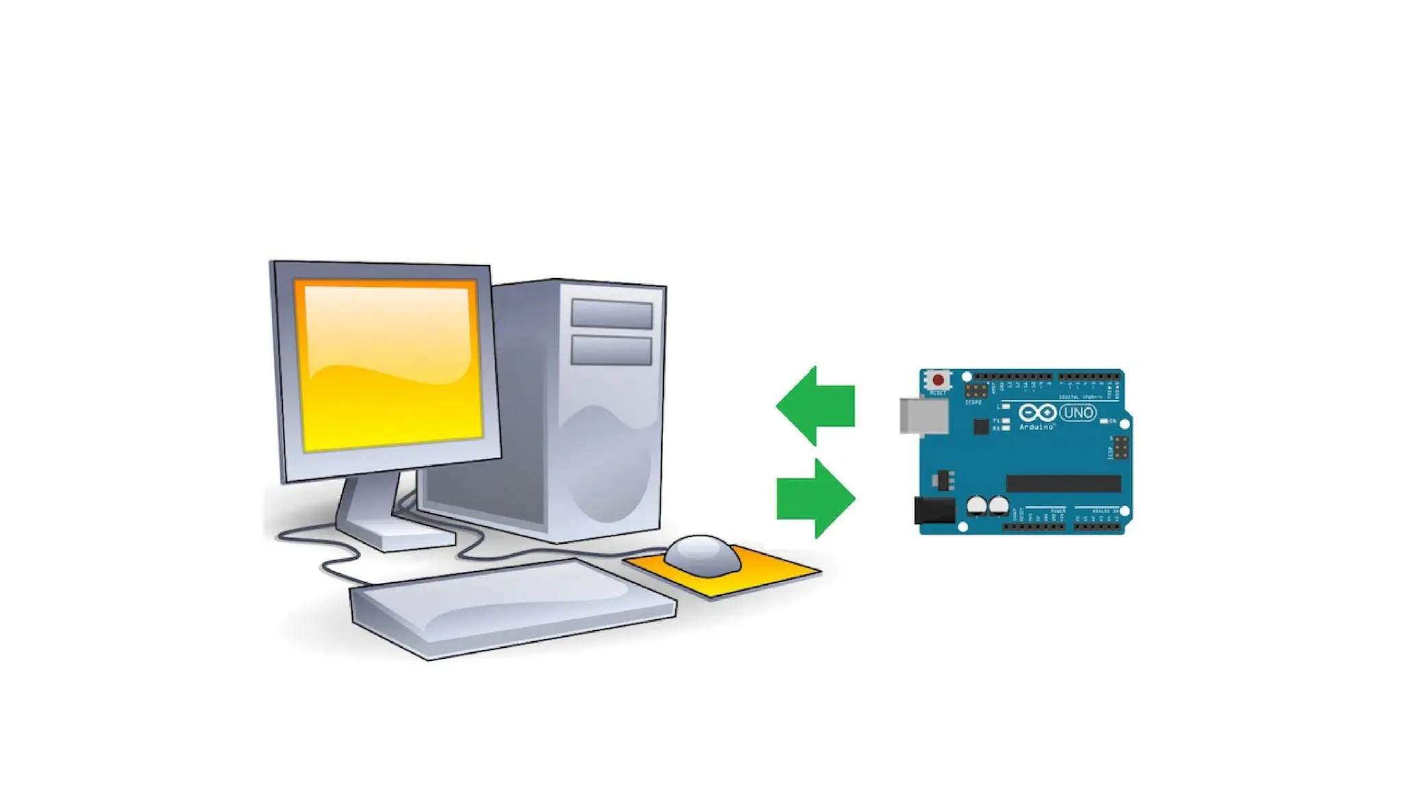
• The communication between Arduino UNO (or any other board) and computer is serial communication.
• Serial communications provide an easy and flexible way for Arduino board to interact with the computer and
other devices
• Serial communications are also a handy tool for debugging.
7.
Serial communication inArduino
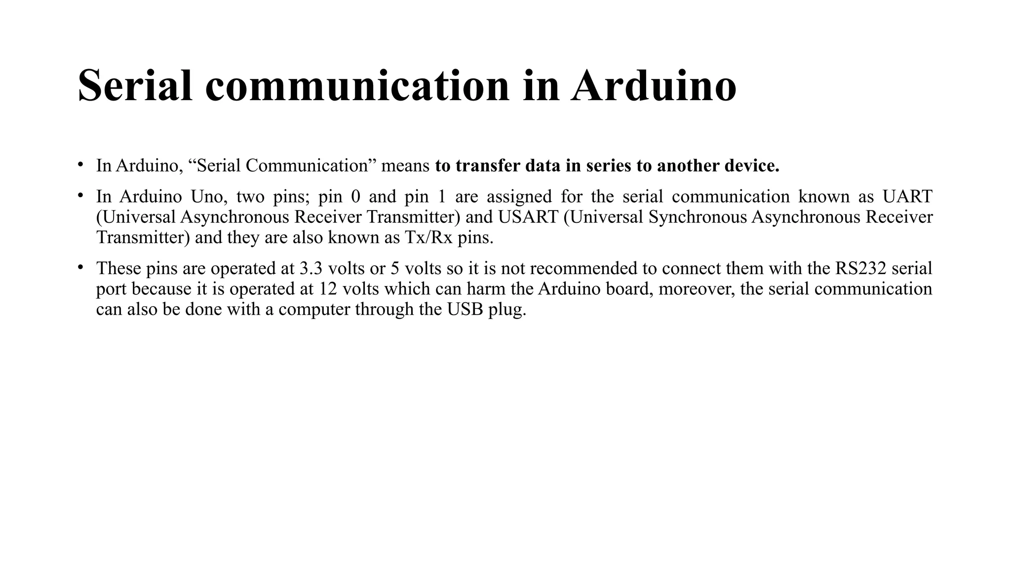
• In Arduino, “Serial Communication” means to transfer data in series to another device.
• In Arduino Uno, two pins; pin 0 and pin 1 are assigned for the serial communication known as UART
(Universal Asynchronous Receiver Transmitter) and USART (Universal Synchronous Asynchronous Receiver
Transmitter) and they are also known as Tx/Rx pins.
• These pins are operated at 3.3 volts or 5 volts so it is not recommended to connect them with the RS232 serial
port because it is operated at 12 volts which can harm the Arduino board, moreover, the serial communication
can also be done with a computer through the USB plug.
8.
Serial communication inArduino
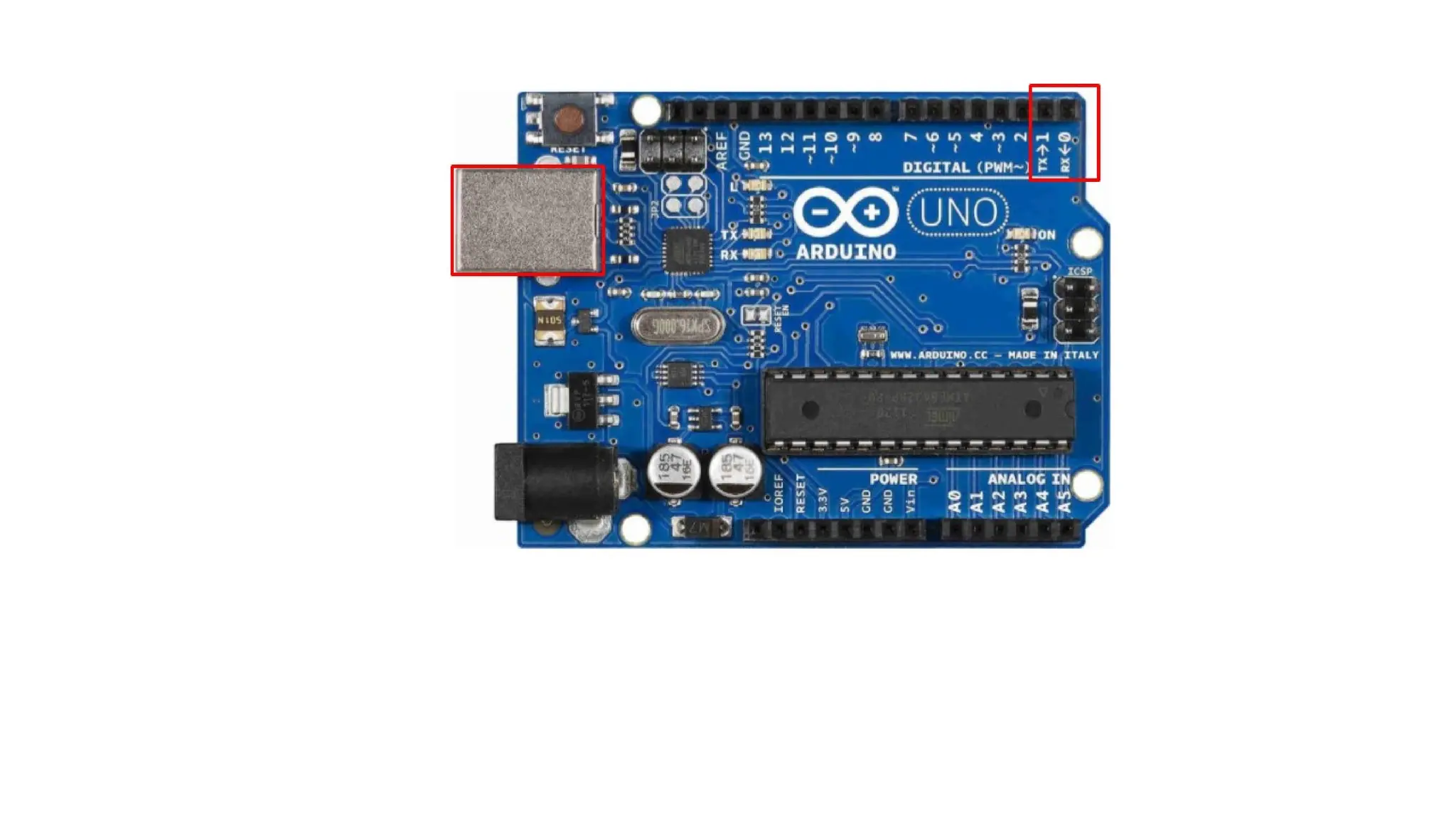
• In the figure of Arduino Uno, the pin 0 and pin 1 are specified with TX/RX used for serial communication,
also a USB plug is present for the serial communication with the computer.
10.
Serial communication inArduino
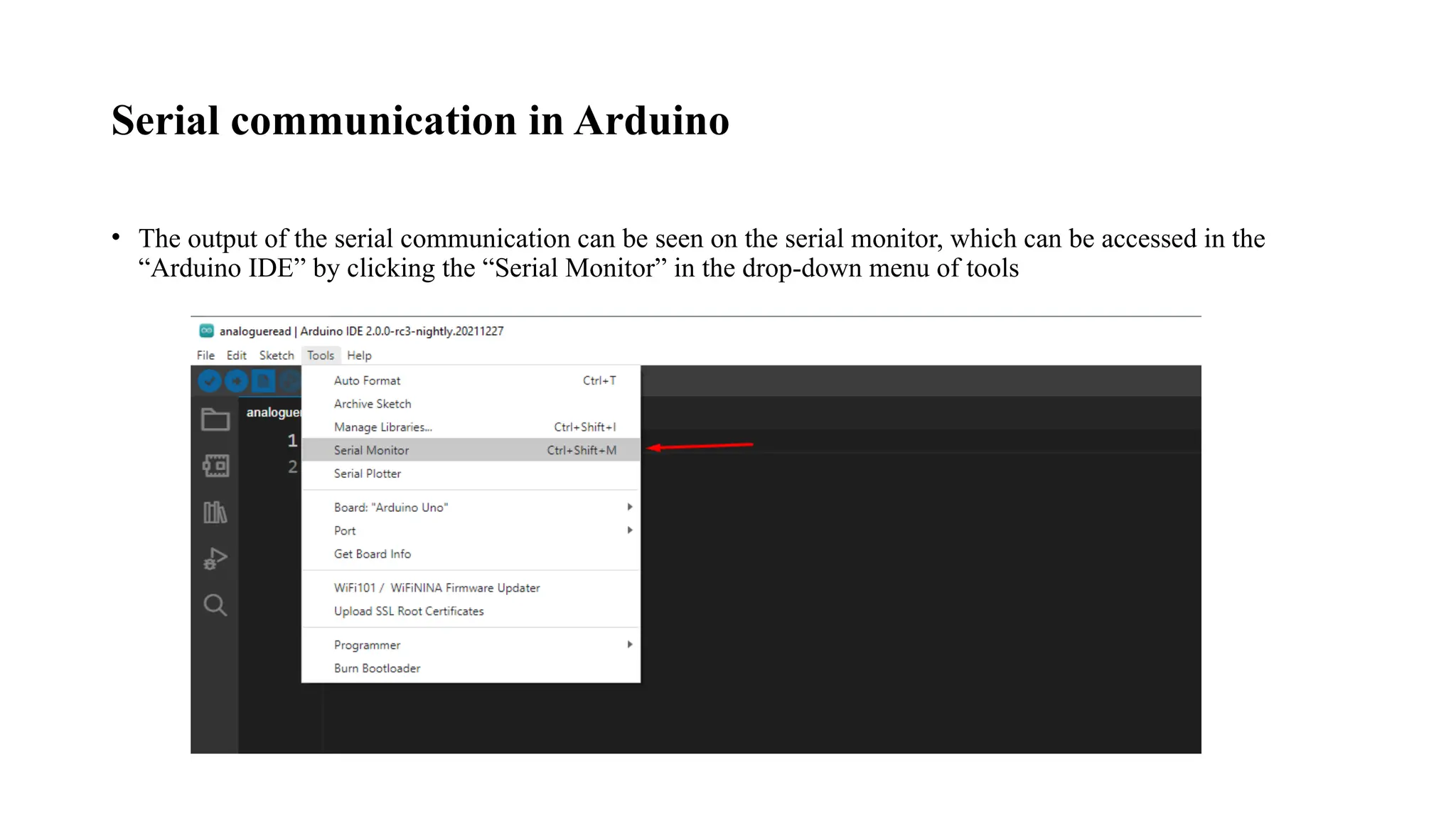
• The output of the serial communication can be seen on the serial monitor, which can be accessed in the
“Arduino IDE” by clicking the “Serial Monitor” in the drop-down menu of tools
11.
Communication in Arduino
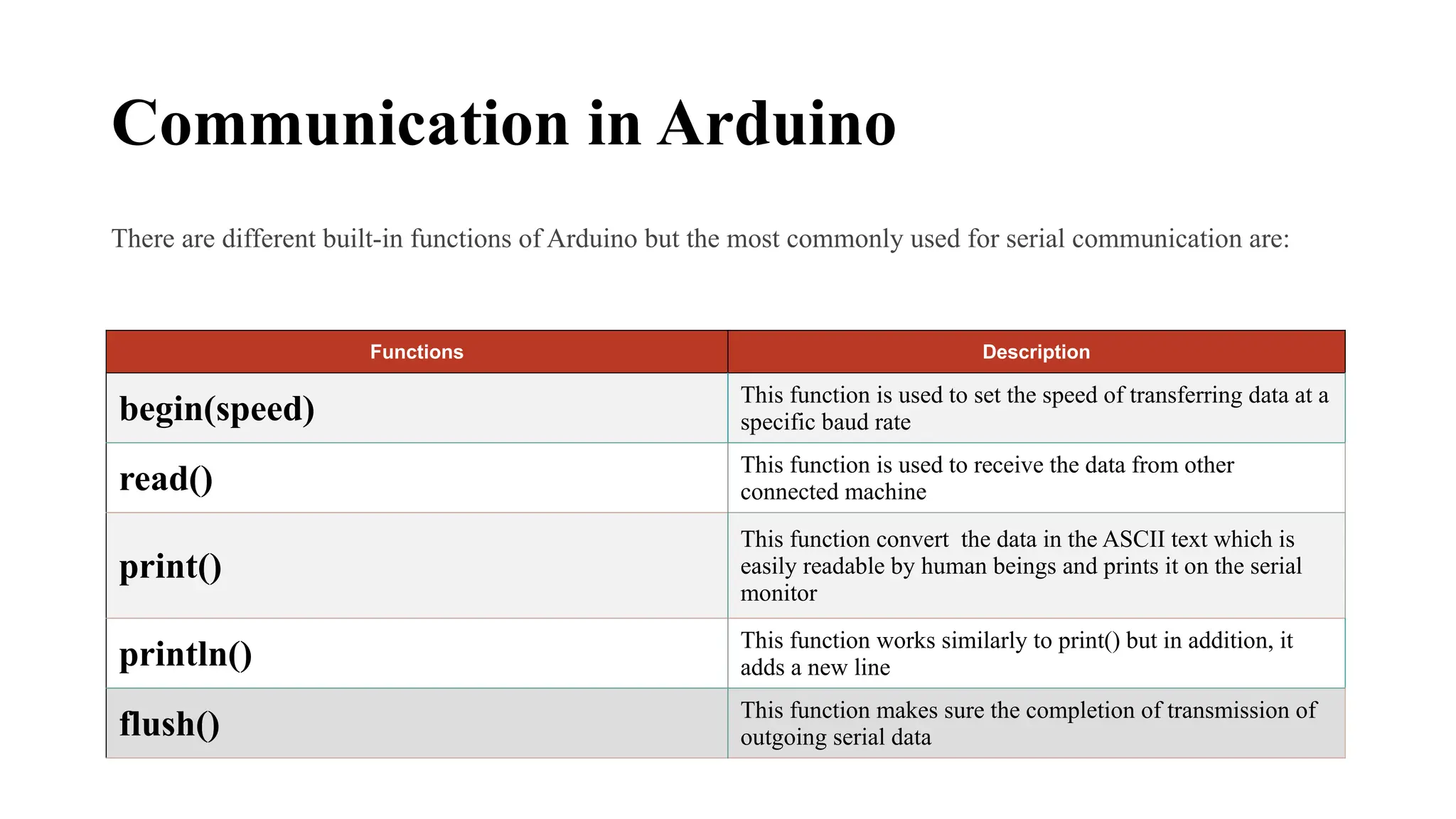
Thereare different built-in functions of Arduino but the most commonly used for serial communication are:
Functions Description
begin(speed) This function is used to set the speed of transferring data at a
specific baud rate
read() This function is used to receive the data from other
connected machine
print()
This function convert the data in the ASCII text which is
easily readable by human beings and prints it on the serial
monitor
println() This function works similarly to print() but in addition, it
adds a new line
flush() This function makes sure the completion of transmission of
outgoing serial data
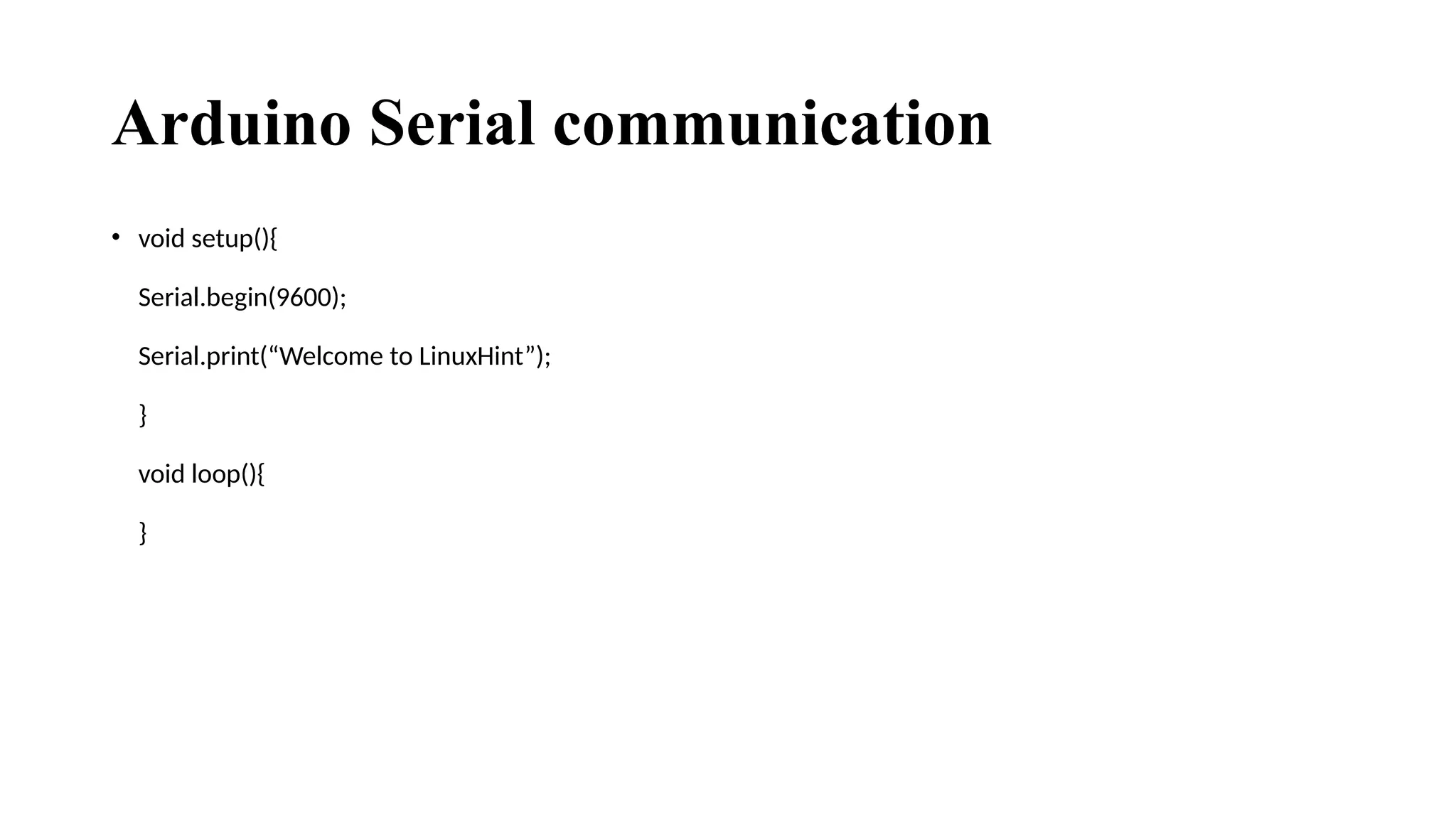
Serial.begin
• Serial.begin isa function that is used to begin the serial communication and also set the data transfer rate for
communication.
• The syntax of Serial.begin is Serial.begin (baud rate);
• In the syntax, the baud rate indicates how many bits we are going to transfer in one second.
• The units of baud rate is bits per second (bps) and the common values of baud rate are 9600 bps, 19200 bps,
115200 bps etc.
• The preferred baud rate in most devices is 9600 bps and the default value in Arduino’s serial terminal is also
the same. Hence, in the sketch, we will initialize the serial communication by writing Serial.begin (9600); in
the setup function.
15.
Serial.println
• After initializing,the next step is to send data to the serial terminal of the Arduino, which will be displayed
on the computer screen.
• In order to do that, another function called “Serial.println” is used
• Using Serial.println function, we can transmit data from the Arduino to computer that can be seen on the
serial monitor. The syntax of Serial.println function is Serial.println (“Data”);
• In place of Data in the Serial.println function, we have to write the actual data that has to be transmitted.
16.
Serial Hardware
• Serialhardware sends and receives data as electrical pulses that represent sequential bits.
• The zeros and ones that carry the information that makes up a byte can be represented in various ways.
• The scheme used by Arduino is 0 volts to represent a bit value of 0, and 5 volts (or 3.3 volts) to represent a bit
value of 1.
• Using 0 volts (for 0) and 5 volts (for 1) is very common. This is referred to as the TTL level because that was
how signals were represented in one of the first implementations of digital logic, called Transistor- Transistor
Logic (TTL).
• Boards including the Uno, Duemilanove, Diecimila, Nano, and Mega have a chip to convert the hardware
serial port on the Arduino chip to Universal Serial Bus (USB) for connection to the hardware serial port.
• Other boards, such as the Mini, Pro, Pro Mini, Boarduino, Sanguino, and Modern Device Bare Bones Board,
do not have USB support and require an adapter for connecting to your computer that converts TTL to USB.