1. CHEMICAL ENGINEERING WWW.CHEMENGONLINE.COM SEPTEMBER 201546
M
ost engineers have likely
heard the term NPSH
(net positive suction
head) at some point in
their careers. Put simply, NPSH is the
net pressure available at a pump’s
suction flange, expressed either as a
height or a pressure value. Why is it
so important? How is it calculated?
What needs to be done to increase
NPSH? What best practices are as-
sociated with NPSH? This article
covers all these points in detail using
practical examples. After reading this
article, engineers will have a basic
understanding of NPSH concepts
and calculations, as well as the abil-
ity to solve simple NPSH problems.
Basic terminology
The first step in understanding NPSH is to
briefly define important basic terms that will
help in clarifying the meaning of NPSH and
guide engineers in its calculation.
Vapor pressure. By definition, vapor pressure
is the pressure exerted by the vapor that is in
contact with the fluid in consideration. This is
the pressure exerted by vapor in thermody-
namic equilibrium with its condensed phases
at a given temperature. The vapor pressure
of any liquid increases non-linearly with tem-
perature, and at an elevated temperature, the
vapor pressure equals the atmospheric pres-
sure. When this happens, the fluid starts boil-
ing.Forexample,consideraverycommonfluid
— water. The vapor pressure of water at 10°C
is 0.22 psia, while its vapor pressure at 100°C
is 14.7 psia. Vapor pressure always increases
with operating temperature and is most often
expressed in psia.
Atmospheric pressure. The surrounding
atmosphere exerts a constant pressure on
everything. This pressure depends on the
elevation relative to sea level, and starts de-
creasing with increasing elevation as the at-
mosphere starts getting thinner. It is nearly
always expressed in psia.
Specific gravity. The ratio of the density of
a fluid to the density of a referenced fluid is
known as specific gravity. In most engineer-
ing calculations, the referenced fluid is water.
Specific gravity is dimensionless.
Subcooled liquid. A liquid that exists below
its normal saturation temperature is called a
subcooled liquid. For example, water at at-
mospheric pressure boils at 100°C. Water at
50°C is a subcooled liquid.
Saturated liquid. A liquid that exists at the
saturation temperature or boiling point that
corresponds to a given operating pressure is
said to be saturated. If any energy is added to
the liquid, and the pressure is kept constant,
some of the liquid will boil. A good example is
a typical pressure cooker. A pressure cooker
operatesatelevatedpressuresothatthewater
can boil at an elevated temperature to properly
cook food. If the pressure inside the cooker is
decreased, the water would boil instantly and
the pressure would be released in the form of
steam. Another example is the liquid inside
a distillation column that always exists at a
saturated temperature.
Asif Raza
Equipment Design
Engineer
Determining net positive suction head (NPSH) can be confusing,but with these guidelines,
engineers can avoid the pitfalls of incorrect calculations
Calculate NPSH
with Confidence
IN BRIEF
BASIC TERMINOLOGY
HOW NPSH IS
CALCULATED
IMPLICATIONS OF
INACCURATE NPSH
WAYS TO INCREASE
NPSH
ENGINEERING BEST
PRACTICES
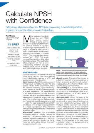
FIGURE 1. Drawing a system sketch is extremely helpful for
gaining a better understanding of the system, and can be
used to revise calculations during detailed design, especially
if assumptions made during the basic design have changed
Operating pressure
= 0 psig
Suction vessel
Pump
8 ft
Grade
2 ft
2. CHEMICAL ENGINEERING WWW.CHEMENGONLINE.COM SEPTEMBER 2015 47
NPSH available and required. The NPSH
available (NPSHa) is a function of the system
and should be calculated based on system
design. The NPSH required (NPSHr) is a
function of the pump itself and should be ob-
tained from the pump manufacturer.
How NPSH is calculated
NPSH can be a difficult concept to grasp.
To explain NPSH in simple terms, imagine a
bonus received on a paycheck. However, the
amount actually deposited into the bank ac-
count is much less than the bonus value, and
it is later realized that the rest of the money has
been deducted as taxes. What was deposited
is the actual net bonus. It is a similar case for
NPSH, which is the net pressure available for
pump suction after all deductions, such as line
losses and vapor pressure, are taken into ac-
count. In other words, it is the pressure avail-
able in excess over the vapor pressure to pre-
vent the pumping fluid from boiling. The aim
with NPSH is to provide an adequate amount
of head exceeding the fluid’s vapor pressure to
prevent the fluid from boiling at the pump inlet.
This excess head is defined as NPSH.
Calculating NPSH is relatively simple once
the correct data have been collected. The
sections below detail each piece of data that
is required for NPSH calculations.
Site atmospheric pressure. NPSH calcula-
tions are impacted by the site’s local condi-
tions — specifically atmospheric pressure.
This value is used in NPSH calculations, and
the higher the atmospheric pressure, the bet-
ter, with regard to NPSH. For instance, if a
site is located in Mumbai, India, which is at
sea level, the atmospheric pressure is exactly
14.7 psia. Hypothetically, if the site location
is at a much higher elevation, say on Mount
Everest, which is about 29,000 ft above sea
level, the atmospheric pressure is just 4.4
psia. This puts into perspective the effect of
site location on atmospheric pressure. So, it
is crucial to do due diligence and find the cor-
rect atmospheric pressure for a site’s location.
Suction piping layout. The physical layout
of the suction piping is important in deter-
mining NPSH. This information must include
the exact number of pipe fittings in order
to properly determine the suction-piping
pressure drop.
Vapor pressure of the pumping fluid. As
explained earlier, vapor pressure is dependent
on the operating temperature. Vapor pres-
sure for pure substances can be found in lit-
erature, such as Perry’s Chemical Engineers’
Handbook [1]. There are also many resources
available online, including Ref. 2, which has a
comprehensive list of pure substances in its
database. To determine the vapor pressure,
the operating temperature must be provided.
Suction vessel elevation and operating
pressure. It has already been stated that the
overall site elevation affects the NPSH of a
given pump layout. The elevation of the suc-
tion vessel (the tank or vessel from which the
liquid is being pumped) itself is also impor-
tant. Additionally, the operating pressure of
the suction vessel must be known. A system
sketch can be helpful in visualizing the pump-
ing system layout and the suction elevation.
Figures 1 and 2 show some examples of
typical pumping system sketches.
Pump dimensional drawings. If available
during early stages in design, a sketch of the
specific pump model can be very helpful.
Now that the basic terms and required data
have been outlined, actual NPSH calculation
can begin. Consider this example comparing
water at two temperatures. Water is being
pumped from a vessel at atmospheric pres-
sure at a rate of 200 gal/min. The suction line
is 3-in. carbon steel and the site atmospheric
pressure is 13 psia. How will the NPSH be im-
pacted by temperature if the water is at 95°C?
What if the water temperature is 30°C? Assume
this is a new design and the tank elevation and
piping layout are fixed. The following are the re-
quired steps for solving this problem:
Contact the pump vendor and get a pump1.
datasheet based on the process data. Ven-
dors will often provide a value for the re-
quired NPSH of a particular pump model.
For this example, assume that the pump
vendor lists NPSHr as 6 ft. Figure 3 shows
the relationship between NPSHr and flow-
rate from a typical pump curve. Pump
FIGURE 2. This system sketch
shows a pump configura-
tion where there is negative
suction lift, meaning that the
pump is located higher than
the source suction vessel.
The low liquid level should be
considered in NPSH evalua-
tions for a more conservative
approach
Low
liquid
level
Grade
150 gal/min
5 ft
2 ft
FIGURE 3. Vendor-provided
pump curves provide engi-
neers a wealth of information,
including the NPSH required
for a specific pump model
over a range of flowrates
- 400 800 1,200 1,600 2,000 2,400 2,800 3,200
Flowrate, gal/min
NPSHr,ft
20
15
10
5
0
3. CHEMICAL ENGINEERING WWW.CHEMENGONLINE.COM SEPTEMBER 201548
curves illustrate many useful parameters,
such as the relationship between flowrate
and head, power, NPSH and efficiency. En-
gineers should read all of the parameters
with respect to their pump’s normal and
rated flow, and always base calculations on
their pump’s rated flowrate. Notice that the
NPSHr curve is slightly bowl-shaped, and
that NPSHr increases with flow. Make sure
that the entire operating range is taken into
consideration while reading a pump curve.
Calculate the pressure drop in the suction2.
line as accurately as possible, considering
the layout and all fittings.
Obtain the pump dimensional drawing from3.
the vendor.
Get the source (suction) vessel drawing4.
to see the orientation of the nozzles and
the elevation.
Determine the respective vapor pressure of5.
water at each considered temperature. In
this example, the vapor pressure of water
at 95°C is 12.26 psia and the vapor pres-
sure of water at 30°C is 0.615 psia.
Determine the site atmospheric pressure.6.
For this example, it is 13 psia.
Table 1 shows the calculations required to
determine the NPSH available for water at
each temperature with the inputs defined in
the preceding sections. Table 2 illustrates the
NPSH calculations at 30°C in a negative suc-
tion-lift scenario. Based on good engineering
practice, an assumed design margin (3 ft) is
applied, meaning that the NPSHa should be
TABLE 1.NPSH CALCULATIONS FOR WATER AT 95 AND 30°C
Water at 95°C Water at 30°C
Input data Calculated values Input data Calculated values
Atmospheric pressure at project site 13 psia 13 psia
Liquid specific gravity 1 1
Pressure above the liquid (operating pressure) 0 psig (13+0) × 2.31/1 = 30.03 ft 0 psig (13+0) × 2.31/1= 30.03 ft
Static head (distance from the low-low liquid level in ves-
sel to the pump suction flange)
6 ft 6 ft 6 ft 6 ft
Suction friction losses (calculated based on suction-piping
isometrics and pump rated flowrate)
0.5 psid 0.5 × 2.31/1 = 1.16 ft 0.5 psid 0.5 × 2.31/1 = 1.16 ft
Pressure at pump suction (pressure head above liquid +
static head – piping suction loss)
ft (30.03 + 6) - 1.16 =
34.87
ft ft (30.03 + 6) – 1.16 =
34.87
ft
Vapor pressure at operating temperature 12.26 psia 12.26 × 2.31 / 1 = 28.32 ft 0.615 psia 0.615 × 2.31 / 1 = 1.42 ft
NPSH available (pressure head at pump suction – vapor
pressure)
34.87 – 28.32 = 6.55 ft 34.87 – 1.42 = 33.45 ft
NPSH (required) based on pump vendor’s datasheet 6 ft 6 ft
Satisfactory margin of 3 ft over NPSH required 6 + 3 = 9 ft 6 + 3 = 9 ft
Compare NPSH available versus NPSH required Margin of 3 ft or more
available?
No Margin of 3 ft or more
available?
Yes
TABLE 2.NPSH CALCULATIONS FOR WATER AT 30°C WITH NEGATIVE SUCTION LIFT
Water at 30°C
Input data Calculated values
Atmospheric pressure at project site 13 psia
Liquid specific gravity 1
Pressure above the liquid (operating pressure) 0 psig (13 + 0) × 2.31 / 1 = 30.03 ft
Negative static head (distance from the low-low liquid level to the pump suction flange) 5 + 2 = 7 ft 5 + 2 = 7 ft
Suction friction losses (calculated based on suction piping isometrics and pump rated flowrate) 1.5 psid 1.5 × 2.31 / 1 = 3.46 ft
Pressure at pump suction (pressure head above liquid – negative static head – piping suction loss) ft (30.03 – 7) – 3.46 = 19.61 ft
Vapor pressure at operating temperature 0.615 psia 0.615 × 2.31 / 1 = 1.42 ft
NPSH available (pressure head at pump suction – vapor pressure) 19.61 – 1.42 = 18.19 ft
NPSH (required) based on pump vendor's datasheet 6 ft
Satisfactory margin of 3 ft over NPSH required 6 + 3 = 9 ft
Compare NPSH available versus NPSH required Yes or no? Margin of 3 ft or more available? Yes
4. CHEMICAL ENGINEERING WWW.CHEMENGONLINE.COM SEPTEMBER 2015 49
at least 3 ft greater than the NPSHr.
Based on the given inputs, the NPSH
at 95°C is 6.55 ft, but the NPSH at 30°C
is 33.45 ft. The static head and pip-
ing friction loss are the same in both
cases; the only difference is the vapor
pressure, which is much higher for the
higher temperature case. This illustrates
why using an accurate vapor pressure
is crucial, as it has a significant effect on
the calculations.
Very special care should be taken
when dealing with boiling liquids or sat-
urated liquids, such as the liquids from
distillation columns or from reflux con-
densers. In these situations, the operat-
ing pressure does not help, and no credit
can be taken, since the vapor pressure
will be equal to the operating pressures.
In these cases, high static head and low
friction losses in the suction piping are
the only additional sources of gain.
Implications of inaccurate NPSH
As explained earlier, if excess head is
not provided over the vapor pressure,
the fluid starts boiling at the pump inlet.
Instead of a steady stream of liquid en-
tering the pump inlet, two-phase flow
is introduced at the eye of the pump
impeller. The pump impeller moves the
fluid to a higher pressure and the void of
gas present within the boiling fluid starts
collapsing on the impeller with force,
producing a shockwave and, typically,
a loud thudding sound. These collaps-
ing voids cause cyclic stress through
repeated implosion, which starts dam-
aging the impeller. The thudding noises
are due to vapor bubbles collapsing
on the impeller. Some of these prob-
lems occur due to a variety of reasons:
NPSH has not been not calculated cor-
rectly; the pumps have been relocated
in different service (perhaps to sys-
tems with different layout or elevation);
or the process conditions changed
due to suction piping modifications
and the designer did not reassess the
NPSH available.
The problems are more severe in
larger pumps, since increased amounts
of bubbles are formed and implode on
the high-pressure side of the impeller.
When this happens, the capacity of the
pump is greatly reduced and the impeller
sustains damage. Additionally, the radial
and thrust bearings can be damaged
because the energy absorbed by the
pump is not effectively transferred to the
fluid. Sometimes the problem may be so
severe, especially in high-speed pumps,
that the shaft is subjected to high levels
FIGURE 4. Flow inducers can be
installed inside the pump casing to
decrease the NPSH required. Flow
inducers are available in many
sizes and metallurgical options
Call on the
Screening
Experts
Replace your existing bar
screens on line, without any
basin modifications with our
unique, continuous screening
Vari-Flow SS Series
Traveling Sump Screen
Traveling Sump Screen
The Vari-Flow SS Series
Traveling Sump Screen is
custom fabricated to easily
replace stationary screens while
your unit stays in full operation.
The screens can be automated
and are available in more than
20 different screen-mesh sizes.
The Traveling Sump Screen is
patented, manufactured and
distributed by Industrial Cooling
Tower Services. Let the experts
handle your equipment
screening needs with this easy-
to-use, cost efficient solution.
Circle 22 on p. 94 or go to adlinks.chemengonline.com/56201-22
5. CHEMICAL ENGINEERING WWW.CHEMENGONLINE.COM SEPTEMBER 201550
of stress and becomes misaligned.
Engineers should be very careful and com-
plete the proper analyses before selecting
a pump and finalizing the system design.
Once the system design is complete and
constructed, very little can be done to alter
the system, and the only option may be to
change the pump or re-configure the suc-
tion piping, both resulting in additional costs
and downtime.
This phenomenon occurred in a poly-
isobutane plant where two reactor-bottoms
pumps were installed. The more recently
installed pump would cavitate because
proper NPSH calculations were not car-
ried out for the new pump’s piping layout.
The new pump-suction piping length was
routed with many elbows, and the pressure
drop was high, leading to a lower NPSH
available for the pump, which was not con-
sidered when the pump was installed. The
suction piping had to be re-routed, which
effectively increased the available NPSH.
However, all of these modifications were
completed during plant shutdown, resulting
in considerable production losses. Diligently
collecting the proper data for NPSH calcu-
lations can make a significant impact on
plant operations.
Ways to increase NPSH
Frequently during the early design stage of a
project, the NPSH calculations are based on
a preliminary piping layout. This is when engi-
neers may find that they are dealing with low
NPSH. Steps that can be taken to increase
NPSH are as follows:
Contact the piping-layout designer to see
whether they can increase the elevation of
the suction vessel
Check whether increasing the size of the
suction piping reduces the pressure drop
and increases the NPSH available
Consult with the vendor to see if a bigger
impeller is available. Pumps with larger
impellers have better NPSH values. How-
ever, the penalty for bigger impellers is a
higher power consumption
Check with the vendor for a slower-speed
motor. Pump manufacturers may suggest
a slow-speed motor to reduce NPSH-re-
lated problems. With a slower motor, high
static head is available at the suction and
improves NPSH
Determine whether the pump can be
physically lowered inside a pit or sump to
increase the static head
If the process allows, lower the tempera-
ture of the pumping process to decrease
vapor pressure. A practical example is a
molten-sulfur pump in a batch process
that cavitated when the temperature of
the reactor was high; the high temperature
led to high vapor pressure and decreased
NPSH availability. The plant personnel
analyzed the problem, and instead of
changing the pump, they decided to install
a cooling-water jacket on the suction
piping. The slight cooling of the fluid was
enough to adequately run the pump
Check with the pump vendor to determine
whether a flow inducer (Figure 4) is avail-
able for your pump. If available, ask for a
NPSH curve that also shows the NPSH
with a flow inducer installed (Figure 5)
and check the NPSH requirement. A flow
inducer is a small impeller that is installed
inside the pump casing just before the
pump’s main impeller. Simply, it can be
defined as a small booster pump ahead
of the main pump that increases the static
pressure of the pumping fluid at the pump
suction, reducing the NPSHr. The NPSH
requirement of the flow inducer is very low
Now that the implications of improper NPSH
calculations and the benefits of flow inducers
are understood, consider another example
problem. There is an existing cryogenic pump
FIGURE 5. Notice how the
NPSH requirement of the
pump is decreased with the
addition of a flow inducer.
It is worth mentioning here
that the NPSH requirement of
the pump increases sharply
with increasing flow. It is very
important to operate the pump
within the specified range
where the NPSH is within
acceptable limits
FIGURE 6. The pump curve
shows not only the NPSH,
but also the shaft power, ef-
ficiency and head, across the
pump’s entire operating range
— NPSH with conventional inducer
— NPSH without inducer
[ft]
230
220
210
200
190
180
170
160
150
140
130
120
110
100
90
80
70
60
[%]
30
20
[hp]
8
4
[ft]
6
4
NPSHr
Flowrate
0 10 20 30 40 50 60 70 80 90 100 110 120 gal/min
Head Application range
Operating point 1New NPSH curve
with flow inducer
Operating point 2
Operating
point 2
Operating
point 1
Efficiency
Shaft power
NPSH
206 ft
45.1%
11.3 hp
5.15 ft
6. CHEMICAL ENGINEERING WWW.CHEMENGONLINE.COM SEPTEMBER 2015 51
in liquid argon service that is designed for 60
gal/min at 210 ft of head. The plant decides
to relocate the pump to a location where 90
gal/min at 180 ft of head is required. Here,
it must be determined whether the pump
can be used in this newly specified service,
and any potential modifications required to
achieve this must also be evaluated. Figure
6 shows the pump curve for the pump in
question. The steps for solving this problem
are as follows:
Check the pump curve to make sure that1.
the pump can achieve the desired head
at the requested flowrate. Draw a straight
line from 90 gal/min on the capacity-head
chart and then read the corresponding
head value. It is seen that it is possible to
achieve 90 gal/min at 180 ft of head.
Calculate the NPSH available from the2.
sample calculations discussed earlier.
For this instance, assume the available
NPSH is 6 ft.
Read the NPSH curve in Figure 6 to check3.
the NPSHr at 90 gal/min. It is 6 ft, and the
available NPSH is also 6 ft. In this scenario,
there is no room for the minimum design
margin of 2 ft, hence the NPSH avail-
able must somehow be increased. Based
on the previously provided guidelines on
what can be done to increase NPSH,
consider whether using a flow inducer
may work.
Contact the vendor and ask whether there4.
is a flow inducer available for this pump.
Assume that the vendor confirms that there
is indeed a flow inducer available, and pro-
vides a pump curve with the flow inducer.
It is seen in Figure 6, that with the flow in-
ducer, the NPSH requirement at 90 gal/min
drops to 4 ft. Now, there is a design margin
of 2 ft available, satisfying the design re-
quirements. Therefore, with the installation
of a flow inducer, this design change can
be implemented.
The final step is to confirm with the vendor5.
regarding the new horsepower require-
ment at the higher flowrate of 90 gal/min
at 180 ft of head. Use this information to
make sure the existing motor is adequate
or if it will need replacement. Working with
an electrical engineer may be required to
make the correct decision regarding pump
motor replacement.
Engineering best practices
While calculating NPSH, follow these guide-
lines to ensure a quality system design:
Calculate NPSH using the low liquid level1.
in the suction tank. This is a conservative
approach, and ensures that a pump will
work, even at low liquid levels. This also
ensures that the liquid inventory in the
storage tank is utilized to the fullest.
To avoid excessive pressure drop, design2.
the suction piping with the minimum num-
ber of elbows and fittings. Also, suction
piping should be short as possible. Target
a maximum pressure drop of 0.5 psi.
If the pump is connected with a reducer,3.
use an eccentric reducer with the flat side
up. This arrangement ensures that the en-
trained vapor bubbles will migrate back to
the source instead of remaining near the
pump suction. Be sure to follow any spe-
cific installation procedure that is recom-
mended by the pump vendor.
If the line is insulated for personnel pro-4.
tection, consider removing the insulation
and installing a metal barrier for person-
nel protection. Removing the insulation
will help the fluid to cool down, lower the
vapor pressure and achieve a higher value
for NPSH available.
A design margin of at least 2–3 ft should5.
be allowed between the NPSH required
and the NPSH available. The NPSH avail-
able should always be greater than the
NPSH required.
Through close coordination with pump
vendors and the development of a solid
understanding of the basic terms, includ-
ing vapor pressure, saturation, pressure
drop and rated flow, engineers will be on
the right track to calculate NPSH and prop-
erly design pumping systems that meet
customer or plant requirements.
Edited by Mary Page Bailey
Acknowledgements
The author would like to thank Nikhil Joshi of Praxair Inc. and
Kevin Dilling of Cryogenic Industries for their valuable input.
References
1. Green, D.W., Perry, R.H., “Perry’s Chemical Engineers’
Handbook,” 8th Ed., McGraw-Hill Professional, New York,
N.Y., 2007.
2. Ohe, Shuzo, Vapor Pressure Calculation, www.e-data.jp/
vpcal1/e/, 2010.
Author
Asif Raza is an equipment design engineer at
Praxair, Canada Inc. (1 City Centre Drive, Suite
1200, Mississauga, Ontario, L5B 1M2; Email:
asifraza_us@yahoo.com). His work involves
the design specifications of major equipment,
including heat exchangers, centrifugal and
screw compressors, cryogenic pumps, chillers
and air-cooled heat exchangers. With more
than 15 years of experience in process de-
sign, his interests include complex hydraulics
calculations, P&ID development, process simulation and sizing and
selection of heat exchangers and pumps. Before joining Praxair,
Raza was a lead process engineer at Zeton Inc., where his work
involved the design and fabrication of pilot plants. Also, he previ-
ously held positions with Bantrel and SNC Lavalin. He holds a
B.S.Ch.E. degree, and is a registered professional engineer and a
member of the Ontario Society of Professional Engineers.
7. CHEMICAL ENGINEERING WWW.CHEMENGONLINE.COM SEPTEMBER 201552
T
o the average person, many of the
raw materials that are commonly
used in the chemical process in-
dustries (CPI) can resemble either a
steaming bowl of alphabet soup — KOH,
NaOH, HCl and HF, for example — or a
bad Scrabble rack — toluene, hexene and
xylene, for instance. However, those who
make a living manufacturing chemical-
based products, such as caustics, acids,
solvents and polymers, know that while
high-value chemicals are pivotal to pro-
duction processes, they can also be ex-
tremely dangerous and potentially harmful
to site personnel and the environment if
not handled properly. If a leak does occur,
the safety of site personnel and surround-
ing communities can be put at risk with the
potential for injury or loss of life.
This is a constant concern for manufac-
turers, as hazardous chemical compounds
are used in a large number of industries and
products, including adhesives, biofuels, pe-
troleum additives, polyurethane foam, coat-
ings and more. In addition to being widely
used and potentially dangerous or hazardous
if mishandled, many chemical compounds
are also extremely expensive. If a leak were to
occur during the handling or transfer of these
products, large costs would be incurred by
the operator due not only to the loss of raw
materials, but also for cleanup and potential
environmental remediation. All of these fac-
tors combine to make the full containment of
dangerous chemicals a primary concern for
facility operators.
Crucial pieces of equipment that are utilized
during the manufacture and handling of dan-
gerous chemicals are the pumps that either
introduce raw materials into the production
process or transfer end products for packag-
ing, storage or shipping to end users (Figure
1). Mechanically sealed pumps are com-
monly used for these transfer activities. This
article illustrates how another pump type —
seal-less pumps — can be employed when
full containment of dangerous and valuable
chemicals is an absolute must.
The Hydraulic Institute (Parsippany N.J.;
www.pumps.org) defines a seal-less pump
as “one in which the rotor is contained in a
Chrishelle
Rogers and
Nicholas
Ortega
PSG,aDovercompany
In cases where full containment of dangerous and hazardous chemicals is necessary,seal-less
pumps can provide many safety and operational benefits
The Benefits of Seal-less
Pumps for Full Product
Containment
FIGURE 1. Almost all chemical transfer applications employ
some sort of pump, and some types of pumps can unfortu-
nately introduce the potential for leaks. Leaks of dangerous
chemicals can be catastrophic, but for applications where
full product containment is required, seal-less pumps can
provide protection
IN BRIEF
SEALING CHALLENGES
SEAL-LESS PUMP
TECHNOLOGIES
SEAL-LESS PUMPS IN
OPERATION
Part 2

![CHEMICAL ENGINEERING WWW.CHEMENGONLINE.COM SEPTEMBER 2015 47
NPSH available and required. The NPSH
available (NPSHa) is a function of the system
and should be calculated based on system
design. The NPSH required (NPSHr) is a
function of the pump itself and should be ob-
tained from the pump manufacturer.
How NPSH is calculated
NPSH can be a difficult concept to grasp.
To explain NPSH in simple terms, imagine a
bonus received on a paycheck. However, the
amount actually deposited into the bank ac-
count is much less than the bonus value, and
it is later realized that the rest of the money has
been deducted as taxes. What was deposited
is the actual net bonus. It is a similar case for
NPSH, which is the net pressure available for
pump suction after all deductions, such as line
losses and vapor pressure, are taken into ac-
count. In other words, it is the pressure avail-
able in excess over the vapor pressure to pre-
vent the pumping fluid from boiling. The aim
with NPSH is to provide an adequate amount
of head exceeding the fluid’s vapor pressure to
prevent the fluid from boiling at the pump inlet.
This excess head is defined as NPSH.
Calculating NPSH is relatively simple once
the correct data have been collected. The
sections below detail each piece of data that
is required for NPSH calculations.
Site atmospheric pressure. NPSH calcula-
tions are impacted by the site’s local condi-
tions — specifically atmospheric pressure.
This value is used in NPSH calculations, and
the higher the atmospheric pressure, the bet-
ter, with regard to NPSH. For instance, if a
site is located in Mumbai, India, which is at
sea level, the atmospheric pressure is exactly
14.7 psia. Hypothetically, if the site location
is at a much higher elevation, say on Mount
Everest, which is about 29,000 ft above sea
level, the atmospheric pressure is just 4.4
psia. This puts into perspective the effect of
site location on atmospheric pressure. So, it
is crucial to do due diligence and find the cor-
rect atmospheric pressure for a site’s location.
Suction piping layout. The physical layout
of the suction piping is important in deter-
mining NPSH. This information must include
the exact number of pipe fittings in order
to properly determine the suction-piping
pressure drop.
Vapor pressure of the pumping fluid. As
explained earlier, vapor pressure is dependent
on the operating temperature. Vapor pres-
sure for pure substances can be found in lit-
erature, such as Perry’s Chemical Engineers’
Handbook [1]. There are also many resources
available online, including Ref. 2, which has a
comprehensive list of pure substances in its
database. To determine the vapor pressure,
the operating temperature must be provided.
Suction vessel elevation and operating
pressure. It has already been stated that the
overall site elevation affects the NPSH of a
given pump layout. The elevation of the suc-
tion vessel (the tank or vessel from which the
liquid is being pumped) itself is also impor-
tant. Additionally, the operating pressure of
the suction vessel must be known. A system
sketch can be helpful in visualizing the pump-
ing system layout and the suction elevation.
Figures 1 and 2 show some examples of
typical pumping system sketches.
Pump dimensional drawings. If available
during early stages in design, a sketch of the
specific pump model can be very helpful.
Now that the basic terms and required data
have been outlined, actual NPSH calculation
can begin. Consider this example comparing
water at two temperatures. Water is being
pumped from a vessel at atmospheric pres-
sure at a rate of 200 gal/min. The suction line
is 3-in. carbon steel and the site atmospheric
pressure is 13 psia. How will the NPSH be im-
pacted by temperature if the water is at 95°C?
What if the water temperature is 30°C? Assume
this is a new design and the tank elevation and
piping layout are fixed. The following are the re-
quired steps for solving this problem:
Contact the pump vendor and get a pump1.
datasheet based on the process data. Ven-
dors will often provide a value for the re-
quired NPSH of a particular pump model.
For this example, assume that the pump
vendor lists NPSHr as 6 ft. Figure 3 shows
the relationship between NPSHr and flow-
rate from a typical pump curve. Pump
FIGURE 2. This system sketch
shows a pump configura-
tion where there is negative
suction lift, meaning that the
pump is located higher than
the source suction vessel.
The low liquid level should be
considered in NPSH evalua-
tions for a more conservative
approach
Low
liquid
level
Grade
150 gal/min
5 ft
2 ft
FIGURE 3. Vendor-provided
pump curves provide engi-
neers a wealth of information,
including the NPSH required
for a specific pump model
over a range of flowrates
- 400 800 1,200 1,600 2,000 2,400 2,800 3,200
Flowrate, gal/min
NPSHr,ft
20
15
10
5
0](data:image/gif;base64,R0lGODlhAQABAIAAAAAAAP///yH5BAEAAAAALAAAAAABAAEAAAIBRAA7)