Download to read offline
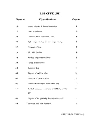
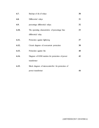
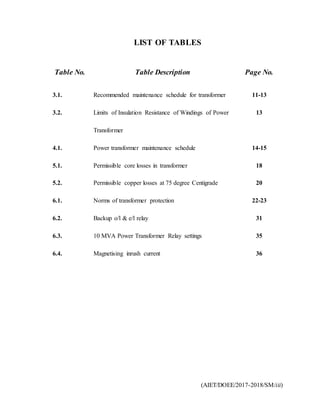

This document contains lists and contents pages for a report on power transformer protection. It includes a list of 15 figures related to transformer components and protection devices. It also includes lists of 3 tables on maintenance schedules and relay settings. The contents section outlines chapters on transformer construction, maintenance, losses, and various protection methods. Protection methods to be discussed include Buchholz relays, differential relays, overcurrent protection, and microcontroller-based protection.