Downloaded 22 times
![Self-Regulat-
ingCables
Power-Limiting
Cables
MineralInsu-
latedCables
Longline
Heating
RTBTubing
Bundles
TankHeatingSnowandIceControland
Monitoring
Heat-Trace
Panels
Engineered
Products
Steam-Tracing
Systems
TechnicalData
Sheets
Appendixes
5 / 32INDUSTRIAL HEAT TRACING SOLUTIONS EN-RaychemSelfRegulating-DG-H56882 08/14
Thermal Design
1. Gather information
2. Calculate
temperature
differential
3. Calculate heat loss
4. Compensate for
insulation type
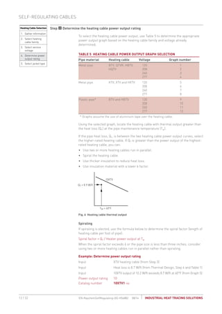
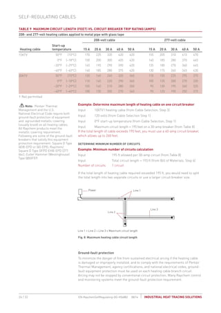
Step Calculate temperature differential ΔT
To calculate the temperature differential (ΔT), use the formula below:
Formula ΔT = Tm – Ta
Example: Calculate temperature differential
Input Tm = 40°F (from Step 1)
Input Ta = –40°F (from Step 1)
Calculation ΔT = 40°F – (–40°F) = 80°F
ΔT = 80°F
Thermal Design
1. Gather information
2. Calculate
temperature
differential
3. Calculate heat loss
4. Compensate for
insulation type
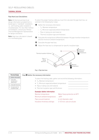
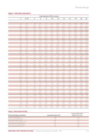
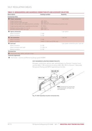
Step Calculate the pipe heat loss
From Table 1 match the pipe size and insulation thickness with the temperature
differential, ΔT, to find the base heat loss of the pipe (Qb).
Example: Calculate pipe heat loss
Input Pipe size = 6 inch (from Step 1)
Input Insulation thickness = 2-1/2 inch (from Step 1)
Input ΔT = 80°F (from Step 2)
Input Pipe heat loss = 3.6 W/ft (from Table 1)
From Table 1, Qb must be calculated through interpolation. For this example, 80°F is
3/5 of the difference between the ΔT of 50°F and the ΔT of 100°F:
Qb = 3.6 W/ft + [3/5 x (7.4 – 3.6)] (7.4 is the ΔT of 100°F; 3.6 is the ΔT of 50°F)
Calculation Qb = 3.6 + 2.3 = 5.9 W/ft
Pipe heat loss Qb = 5.9 W/ft @ 40°F
Thermal Design
1. Gather information
2. Calculate
temperature
differential
3. Calculate heat loss
4. Compensate for
insulation type
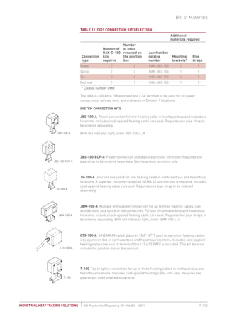
Step Compensate for insulation type
Multiply the base heat loss of the pipe (Qb) from Step 3 by the insulation
compensation factor (f) from Table 2 to get the total heat loss per foot of pipe (Qt).
Formula Qt = Qb x f
Example: Insulation type compensation
Input Insulation type = calcium silicate (from Step 1)
Input f = 1.50 for calcium silicate (from Table 2)
Input Qb = 5.9 W/ft (from Step 3)
Calculation Qt = 5.9 W/ft x 1.50 = 8.85 W/ft
Qt = 8.85 W/ft at 40°F
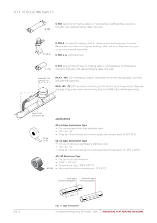
Now proceed to the Heating Cable Selection section, page 8, to determine the
heating cable that will compensate for this heat loss.
Note: Heat loss calculations are based on IEEE Standards.
Thermal Design](https://image.slidesharecdn.com/self-regulating-heat-trace-guide-160228171714/85/Self-Regulating-Heat-Trace-Guide-5-320.jpg)


This document is a detailed design guide for self-regulating heat-tracing systems for insulated pipes and tubing, offering comprehensive technical information and installation procedures. It covers key elements such as conductive-polymer technology, system overview, thermal design calculations, and approvals for use in hazardous locations. The guide provides actionable steps, including pipe heat loss calculations and heating cable selection to effectively design heating solutions.


