Download to read offline
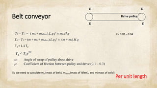
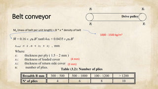
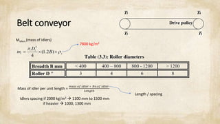
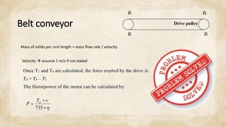
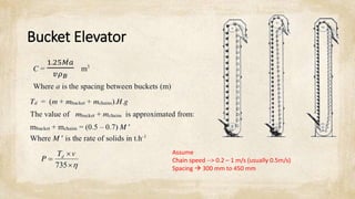

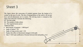

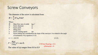
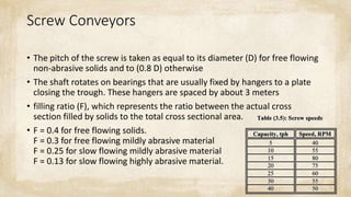


This document discusses common mechanical operations used to transport materials, including belt conveyors, bucket elevators, screw conveyors, and pneumatic transportation. It provides equations and parameters to calculate the mass, power, and other specifications for each type of conveyor. The document includes examples of calculations for belt conveyors, bucket elevators, and screw conveyors based on given parameters. It assumes typical values like belt and material densities, idler spacing, bucket spacing, screw pitch, and filling ratios that can be used in calculations.