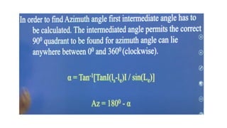
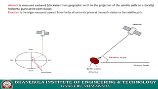
Satellite Communications
Introduction and Historical Background
What is a Satellite?
 Satellite: In astronomical terms, a
satellite is a celestial body that orbits
around a planet.
 Example: The moon is a satellite of Earth.
 In aerospace terms, a satellite is a
space vehicle launched by humans and
orbits around Earth or another celestial
body.
What is a Satellite? (Contd.)
 Communications Satellite: It is a microwave
repeater in the sky that consists of a diverse
combination of one or more components including
transmitter, receiver, amplifier, regenerator, filter
onboard computer, multiplexer, demultiplexer,
antenna, waveguide etc.
 A satellite radio repeater is also called
transponder. This is usually a combination of
transmitter and receiver.
What is a satellite system?
 A satellite system consists of one or
more satellites, a ground-based station
to control the operation of the system,
and a user network earth stations that
provides the interface facilities for the
transmission and reception of terrestrial
communications traffic.
How a satellite works?
 A satellite stays in orbit because the gravitational
pull of the earth is balanced
by the centripetal force of the revolving
satellite.
 One Earth station transmits the signals to the
satellite at Up link frequency. Up link frequency
is the frequency at which Earth station is
communicating with a satellite.
 The satellite transponder process the signal and
sends it to the second Earth station at another
frequency called downlink frequency.
Block diagram of satellite
communication system
Advantages of Satellite Communications
over Terrestrial Communications
 The coverage area greatly exceeds.
 Transmission cost of a satellite is independent
of the distance from the center of the
coverage area.
 Satellite-to-satellite communication is very
precise.
 Higher bandwidths are available for use.
Disadvantages of Satellite
Communications
 Launching satellites into orbits is costly.
 Satellite bandwidth is gradually
becoming used up.
 The propagation delay is larger.
Regions of Space
Space is defined as a place free from obstacles
It can be divided into three regions:
 Air Space -> region below 100 km from earth’s surface
 Outer Space -> also called cosmic space and ranges from
100 km up till 42, 000 km. It is mostly used by
communication satellites.
 Deep Space -> Regions beyond 42,000 km fall in this
category
Active and Passive Satellites
Active satellites are used for linking and also for processing
the signals.
The linkage is known as bent pipe technology where processing
like frequency translation, power amplification etc take place.
Active satellites employ ‘Regenerative Technology’ which consists
of demodulation, processing, frequency translation, switching and power
amplification are carried out. Block used for this purpose is called
transponder.
Passive satellites do-not have on-board processing and are
just used to link two stations through space.
Low cost - Loss of power – not useful for communication
applications.
Orbital Types
Historical Overview
 1945  Theorist named Clarke studied that satellite orbiting in equatorial
orbit at radius of approx. 42,000 km would look as if stationary if moving at a
specific speed. 3 satellites at a space of 120 degree apart can cover the whole
world. Evolution of the concept of GEO
1950’s –Putting the pieces together:
􀂄 1956 -Trans-Atlantic cable opened (about 12 telephone
channels per operator).
􀂄 1957 First man-made satellite launched by former USSR (Sputnik-
1, LEO). It was used to identify atmospheric density of various orbital
layers. It provided data about radio signal distribution in ionosphere.
􀂄 1958 First US satellite launched (SCORE). First voice
communication established via satellite (LEO, lasted 35
days in orbit).
 1960’s –First satellite communications:
 􀂄 1960 First passive communication satellite
(Large balloons, Echo I and II).
 􀂄 1962: First active communication satellite
(Telstar I , MEO).
 􀂄 1963: First satellite into geostationary (GEO)
orbit (Syncom1, communication failed).
 􀂄 1964: International Telecomm. Satellite
Organization (INTELSAT) created.
 􀂄 1965 First successful communications GEO (Early
Bird / INTELSAT 1).
 1970’s –GEO Applications Development,
DBS:
􀂄 1972 First domestic satellite system
operational (Canada).
􀂄 1975 First successful direct broadcast
experiment (USA-India).
􀂄 1977 A plan for direct broadcast satellites
(DBS) assigned by the ITU
􀂄 1979 International Mobile Satellite
Organization (Inmarsat) established.
 1980’s –GEO Applications Expanded, Mobile:
􀂄 1981 First reusable launch vehicle flight.
􀂄 1982 International maritime communications
made operational.
􀂄 1984 First direct-to-home broadcast system
operational (Japan).
􀂄 1987 Successful trials of land-mobile
communications (Inmarsat).
􀂄 1989-90 Global mobile communication service
extended to land mobile and aeronautical use
(Inmarsat)
 1990+’s NGSO applications development and GEO
expansion
1990-95:
􀂄 Proposals of non-geostationary (NGSO) systems for mobile
communications.
􀂄 Continuing growth of VSATs around the world.
􀂄 Spectrum allocation for non-GEO systems.
􀂄 Continuing growth of DBS. DirectTV created.
1997:
􀂄 Launch of first batch of LEO for hand-held terminals (Iridium).
􀂄 Voice-service portables and paging-service pocket size mobile
terminals launched (Inmarsat).
1998-2000:
Mobile LEO systems initiate service and fail afterwards
(Iridium,Globalstar).
Motivation to use the Sky
26-Apr-21 19
Satellite
Communications
Frequency Allocations
 Frequency bands for satellite services are shared with
terrestrial services.
 Satellite signal strength is constrained to avoid
interference by it to others.
 Thus a large antenna and sensitive receiver are needed at
the earth station.
26-Apr-21 20
Satellite
Communications
 Frequency sharing techniques are an important study
area.
 Many satellites have to share a limited frequency
band (and limited orbital arc) thus coordination in
frequency and orbital location is important.
 Frequency allocation are done by international
agreements.
Cont…
Allocation of frequencies to satellite services s a complicated process which
requires international coordination and planning. This is done as per the International
Telecommunication Union (ITU). To implement this frequency planning, the world is
divided into three regions:
Region1: Europe, Africa and Mongolia
Region 2: North and South America and Greenland
Region 3: Asia (excluding region 1 areas), Australia and south-west Pacific.
Within these regions, he frequency bands are allocated to various satellite
services. Some of them are listed below.
 Fixed satellite service: Provides Links for existing Telephone Networks Used for
transmitting television signals to cable companies
 Broadcasting satellite service: Provides Direct Broadcast to homes. E.g. Live
Cricket matches etc
 Mobile satellite services: This includes services for: Land Mobile Maritime Mobile
Aeronautical mobile
 Navigational satellite services : Include Global Positioning systems,
 Meteorological satellite services: They are often used to perform Search and
Rescue service
Different kinds of satellites use different frequency
bands.
 L–Band: 1 to 2 GHz, used by MSS
 S-Band: 2 to 4 GHz, used by MSS, NASA, deep space
research
 C-Band: 4 to 8 GHz, used by FSS the "BUD" (Big Ugly
Dish) band
 X-Band: 8 to 12.5 GHz, used by FSS and in terrestrial
imaging, ex: military and meteorological satellites
 Ku-Band: 12.5 to 18 GHz: used by FSS and BSS
(DBS)
 There are more than 22 FSS Ku band satellites orbiting over North
America, each carrying 12 to 48 transponders,
 K-Band: 18 to 26.5 GHz: used by FSS and BSS
 Ka-Band: 26.5 to 40 GHz: used by FSS
EARTHSTATION FREQUENCIES
BAND FREQUENCY
L 1-2 Ghz
S 2 to 4 GHz
SATELLITE FREQUENCIES (Ghz)
BAND DOWNLINK UPLINK
C 3.700 - 4.200 5.925 - 6.425
X
(Military)
7.250 - 7.745 7.900 - 8.395
Ku
(Europe)
FSS: 10.700 - 11.700
DBS: 11.700 - 12.500
Telecom: 12.500 - 12.750
FSS & Telecom: 14.000 - 14.800
DBS: 17.300 - 18.100
Ku
(America)
FSS: 11.700 - 12.200
DBS: 12.200 - 12.700
FSS: 14.000 - 14.500
DBS: 17.300 - 17.800
K 18 to 26.5 GHz
Ka ~18 - ~31 GHz
DBS = Direct Broadcast Satellite (Consumer direct-to-home Satellite TV)
FSS = Fixed Satellite Service (Geostationary Comms Satellites for TV/Radio stations
and networks)
(Hz = Hertz, Mhz = Megahertz, Ghz= Gigahertz)
Frequency Bands
Applications of Satellites
 o Weather Forecasting
 o Radio and TV Broadcast o Military
 o Navigation
 o Global Telephone
 o Connecting Remote Areas
 o Global Mobile Communication
 Weather Forecasting :
Certain satellites are specifically designed to monitor the climatic
conditions of earth. They continuously monitor the assigned areas of
earth and predict the weather conditions of that region. This is done by
taking images of earth from the satellite. These images are transferred
using assigned radio frequency to the earth station. (Earth Station: it‟s
a radio station located on the earth and used for relaying signals from
satellites.) These satellites are exceptionally useful in predicting
disasters like hurricanes, and monitor the changes in the Earth's
vegetation, sea state, ocean color, and ice fields
Radio and TV Broadcast
These dedicated satellites are responsible for making 100s of
channels across the globe available for everyone. They are also
responsible for broadcasting live matches, news, world-wide radio
services. These satellites require a 30-40 cm sized dish to make these
channels available globally.
Military Satellites
These satellites are often used for gathering intelligence, as a
communications satellite used for military purposes, or as a military
weapon. A satellite by itself is neither military nor civil. It is the kind of
payload it carries that enables one to arrive at a decision regarding its
military or civilian character.
 Navigation Satellites
The system allows for precise localization world-wide, and with
some additional techniques, the precision is in the range of some
meters. Ships and aircraft rely on GPS as an addition to traditional
navigation systems. Many vehicles come with installed GPS receivers.
This system is also used, e.g., for fleet management of trucks or for
vehicle localization in case of theft.
 Global Telephone
One of the first applications of satellites for communication was the
establishment of international telephone backbones. Instead of using cables it
was sometimes faster to launch a new satellite. But, fiber optic cables are still
replacing satellite communication across long distance as in fiber optic cable,
light is used instead of radio frequency, hence making the communication much
faster (and of course, reducing the delay caused due to the amount of distance
a signal needs to travel before reaching the destination.). Using satellites, to
typically reach a distance approximately 10,000 kms away, the signal needs to
travel almost 72,000 kms, that is, sending data from ground to satellite and
(mostly) from satellite to another location on earth. This cause‟s substantial
amount of delay and this delay becomes more prominent for users during voice
calls.
Connecting Remote Areas
Due to their geographical location many places all over the world
do not have direct wired connection to the telephone network or the
internet (e.g., researchers on Antarctica) or because of the current
state of the infrastructure of a country. Here the satellite provides a
complete coverage and (generally) there is one satellite always present
across a horizon
Global Mobile Communication
The basic purpose of satellites for mobile communication is to extend the area of
coverage. Cellular phone systems, such as AMPS and GSM (and their successors) do not cover all
parts of a country. Areas that are not covered usually have low population where it is too
expensive to install a base station. With the integration of satellite communication, however, the
mobile phone can switch to satellites offering world-wide connectivity to a customer. Satellites
cover a certain area on the earth. This area is termed as a „footprint‟ of that satellite. Within the
footprint, communication with that satellite is possible for mobile users. These users communicate
using a Mobile-User-Link (MUL). The base-stations communicate with satellites using a Gateway-
Link (GWL). Sometimes it becomes necessary for satellite to create a communication link
between users belonging to two different footprints. Here the satellites send signals to each other
and this is done using Inter-Satellite-Link (ISL).
Unit-1
Chapter -2
ORBITAL MECHANICS & LAUNCHERS
Orbital Mechanics
Subject: Satellite Communication
Topic: Look Angle Determination
Unit : II
Reference
Satellite Communications, ” Timothy Pratt ,Jeremy Allnutt “, Third
Edition, Wiley 2020.
Learning Outcome
• Students will be able to determine the look angles of a satellite.
Contents
• Look Angle Determination : Azimuthal Angle, Elevation Angle
• Subsatellite Point :Nadir Direction, Zenith Direction
• Azimuthal Angle Measurement
• Elevation Angle Measurement
• Visibility Test
Look Angle Determination
• The coordinates to which an earth station antenna must be pointed to
communicate with a satellite are called the look angles.
• These are most commonly expressed as azimuth (Az) and elevation (El),
although other pairs exist.
• Azimuth Angle
• Elevation Angle
• Generally, the values of these angles change for non-geostationary
orbits. Whereas, the values of these angles don’t change for
geostationary orbits. Because, the satellites present in geostationary
orbits appear stationary with respect to earth.
• These two angles are helpful in order to point at the satellite directly
from the earth station antenna. So, the maximum gain of the earth
station antenna can be directed at satellite.
• We can calculate the look angles of geostationary orbit by using
longitude & latitude of earth station and position of satellite orbit.
• Azimuth Angle
• The angle between local horizontal plane and the plane passing through
earth station, satellite and center of earth is called as azimuth angle.
• Elevation Angle
• The angle between vertical plane and line pointing to satellite is known
as Elevation angle. Vertical plane is nothing but the plane, which is
perpendicular to horizontal plane.
Azimuth is measured eastward (clockwise) from geographic north to the projection of the satellite path on a (locally)
horizontal plane at the earth station.
Elevation is the angle measured upward from the local horizontal plane at the earth station to the satellite path.
• Navigation around the earth’s oceans became more precise when the
surface of the globe was divided up into a grid-like structure of
orthogonal lines: latitude and longitude.
• Latitude is the angular distance, measured in degrees, north or south of
the equator and longitude is the angular distance, measured in degrees,
from a given reference longitudinal line.
• England drew its reference zero longitude through Greenwich, a town
close to London, England, and France, not surprisingly, drew its reference
longitude through Paris, France.
• When GEO satellite systems are registered in Geneva, their (subsatellite)
location over the equator is given in degrees east to avoid confusion.
Thus, the INTELSAT primary location in the Indian Ocean is registered at
60°E and the primary location in the Atlantic Ocean at 335.5°E (not
24.5°W).
• Earth stations that communicate with satellites are described in terms of
their geographic latitude and longitude when developing the pointing
coordinates that earth station must use to track the apparent motion of
the satellite.
The Subsatellite Point
• The subsatellite point is the location on the surface of the earth that lies
directly between the satellite and the center of the earth.
• It is the nadir pointing direction from the satellite and, for a satellite in
an equatorial orbit, it will always be located on the equator.
• Since geostationary satellites are in equatorial orbits and are designed to
stay stationary over the earth, it is usual to give their orbital location in
terms of their subsatellite point.
• To an observer of a satellite standing
at the subsatellite point, the satellite
will appear to be directly overhead, in
the zenith direction from the
observing location.
• The zenith and nadir paths are
therefore in opposite directions along
the same path
• Designers of satellite antennas
reference the pointing direction of the
satellite’s antenna beams to the nadir
direction.
• The communications coverage region on the earth from a satellite is
defined by angles measured from nadir at the satellite to the edges of
the coverage.
• Earth station antenna designers, however, do not reference their
pointing direction to zenith.
• As noted earlier, they use the local horizontal plane at the earth station
to define elevation angle and geographical compass points to define
azimuth angle, thus giving the two look angles for the earth station
antenna toward the satellite (Az, El).
Elevation Angle Calculation
• Figure shows the geometry of the elevation angle calculation.
• rs is the vector from the center of the earth to the satellite
• re is the vector from the center of the earth to the earth
station
• d is the vector from the earth station to the satellite
• These three vectors lie in the same plane and form a triangle.
• The central angle γ measured between re and rs is the angle between
the earth station and the satellite
• ψ is the angle (within the triangle) measured from re to d.
• Defined so that it is non-negative, γ is related to the earth station north
latitude Le (i.e., Le is the number of degrees in latitude that the earth
station is north from the equator) and west longitude le (i.e., le is the
number of degrees in longitude that the earth station is west from the
Greenwich meridian) and the subsatellite point at north latitude Ls and
west longitude ls by
Azimuth Angle Calculation
• Since the earth station, the center of the earth, the satellite, and the
subsatellite point all lie in the same plane, the azimuth angle Az from the
earth station to the satellite is the same as the azimuth from the earth
station to the subsatellite point.
• This is more difficult to compute than the elevation angle because the
exact geometry involved depends on whether the subsatellite point is
east or west of the earth station, and in which of the hemispheres the
earth station and the subsatellite point are located.
Visibility Test
For a satellite to be visible from an earth station, its elevation angle El must be above some minimum value, which is
at least 0°. A positive or zero elevation angle requires that
Exercise Problems
Any Queries ?
Thank You
Orbital Perturbations
Satellite Communications
Chapter-2
Perturbation
 Definition: a deviation of a system, moving object, or process from its
regular or normal state or path, caused by an outside influence.
Types of Orbital perturbations
Perturbations
Third body
Non-gravitational
forces
Non-spherical
masses
•Long term effects Sources:
•Solar radiation
•Outgassing
•Heating
•Atmospheric drag
•Tidal friction
Precession: change
in the orientation of
the orbit (Ω,ω)
Size, shape and
orbital plane:
change in (a,e,i)
of the orbit
• Atmospheric Drag is a non-conservative force and will continuously take
energy away from the orbit.
• The effect of atmospheric friction is to speed up the motion of the satellite as it
spirals inward.
Tidal Friction Effects
 The magnitude of tidal friction effects on the artificial satellites is very small.
 The coupling effect of tidal friction among the massive satellites of the outer
planet, it is responsible for resonance.
Mutual Gravitational Attraction
• Gravitational attractions of the rings will create a torque about the
line of nodes tending to turn the satellite ring into the ecliptic.
•  The gyroscopic effect of the torque on the spinning satellite ring will
induce a gyro precession of the orbit about the pole of the ecliptic,
specifically a regression of the nodes along the ecliptic.
• The moon will cause a regression of the orbit about an axis normal to
the moon's orbit plane, which has a 5-deg inclination with respect to
the ecliptic plane with a node rate of one rotation in 18.6 yr
•
Radiation Pressure Effects
 The effect of solar radiation on particles moving through interplanetary space has been
investigated for many years.
 The typical radiation pressure effect on satellite orbits is the long-term sinusoidal
(yearly for geosynchronous orbits) variations in eccentricity.
 The magnitude of the variation is proportional to:
the effective area
surface reflectivity
inverse of the satellite mass
➢ For a typical communication satellite at geosynchronous altitude, the eccentricity may vary
from 0.001 to 0.004 in six months as a result of solar radiation pressure effects.
➢ In summary, radiation pressure induces periodic variations in all orbital elements, even
exceeding the effects of atmospheric drag. This effects on satellite lifetime.
Thank You
Any Queries?
LAUNCHES AND LAUNCH VEHICLES
 There are two competing technologies:
 Expendable launch vehicle (ELV)
 Space shuttle (STS, for “space
transportation system”).
Expendable launch vehicle(ELV)
 An expendable launch system is a launch system that
uses an expendable launch vehicle (ELV) to carry a
Payload Into Space.
 The vehicles used in expendable launch systems are
designed to be used only once.
 Their components are not recovered for re-use after
launch.
 The vehicle typically consists of several rocket stages,
discarded one by one as the vehicle gains altitude and
speed.
Space shuttle (STS-space transportation system)
 The Space Transportation System (STS) was a proposed
system of reusable manned space vehicles envisioned by NASA
in 1969 to support extended operations beyond the Apollo
program.
 The purpose of the system was twofold: to reduce the cost of
spaceflight by replacing the current method of launching
"capsules" on expendable rockets with reusable spacecraft; and
 To support ambitious follow-on programs including permanent
orbiting space stations around the Earth and Moon, and a human
landing mission to Mars.
LAUNCH CONSIDERATIONS
Launch Windows
 The period of time during which a
satellite can be launched directly into a
specific orbital plane from a specific
launch site
 Window duration driven by safety, fuel
requirements, desired injection points,
etc.
 Window is centered around optimal
launch time
For a spacecraft to achieve synchronous orbit, it
must be accelerated to a velocity of 3070 m/s
in a zero-inclination orbit and raised to a
distance of 42,242 km from the center of the
earth.
Launch Fundamentals
Launch Events
Shroud
Protects the spacecraft
Main vehicle
Primary liquid or solid
rocket propellant tanks
Engine / nozzles
Mechanism for
combining propellants
and focusing thrust
Booster packs
Solid strap-ons for some
rockets to increase
initial thrust
Step 2: Booster cut-off and separation
Step 3: Main engine cut-off and separation
Step 4: Shroud opening
Step 5: Orbit insertion
Step 6: Satellite initial checkout
Step 7: Mechanical deployments
Upper stage
Orbit insertion rocket
engines and propellant
tanks
Step 1: Ignition and launch
Satellite Launch Procedure
The four orbit stages involved in the satellite launch procedure are as follows:
1. Circular low earth orbit
2. Hohmann elliptical transfer orbit
3. Intermediate drift orbit
4. Circular Geostationary orbit
The satellite launch vehicle is a complex system and consists of
following functional modules:
• Propulsion systems
• Auto Piloting
• Aerodynamic structure
• Interactive Steering subsystem
The process of placing the satellite in a proper orbit is known
as launching process. During this process, from earth stations we can
control the operation of satellite. Mainly, there are four stages in launching
a satellite.
•First Stage − The first stage of launch vehicle contains rockets and fuel
for lifting the satellite along with launch vehicle from ground.
•Second Stage − The second stage of launch vehicle contains smaller
rockets. These are ignited after completion of first stage. They have their
own fuel tanks in order to send the satellite into space.
•Third Stage − The third (upper) stage of the launch vehicle is connected
to the satellite fairing. This fairing is a metal shield, which contains the
satellite and it protects the satellite.
•Fourth Stage − Satellite gets separated from the upper stage of launch
vehicle, when it has been reached to out of Earth's atmosphere. Then, the
satellite will go to a “transfer orbit”. This orbit sends the satellite higher into
space.
When the satellite reached to the desired height of the orbit, its
subsystems like solar panels and communication antennas gets unfurled.
Then the satellite takes its position in the orbit with other satellites. Now,
the satellite is ready to provide services to the public.
Launch Fundamentals
Science
force = (mass) x (acceleration)
f = (m)(a)
The thrust of a launch vehicle must oppose gravity and
atmospheric drag
To get into orbit, a vehicle must achieve a velocity of
mach 24 (24 times the speed of sound)
Thrust = Pounds or Kg Impulse = Pounds per sec Specific Impulse (Isp)
= Newtons per sec Isp = Thrust (lb)
fuel weight (lb) burned in 1 sec
FORCE FORCE & TIME FORCE & TIME & FUEL
Mass Ratio of a Vehicle
Mass Ratio (MR) is the ratio between the booster mass
before the rocket engine burn (mf ) divided by the booster
mass after rocket engine burn (m0 ).
MR = mf /m0
PROPULSION: GETTING INTO AND
AROUND IN ORBIT
NORTH
POLE
NORTH
POLE
NORTH
POLE
LAUNCH INTO PARKING ORBIT
(WITH ORBIT INSERTION BURN)
ORBIT PLANE TRANSFER
(WITH VECTOR THRUST BURN)
HOHMANN (MINIMUM ENERGY) TRANSFER
(BURN 1 TO CHANGE TO ELLIPTICAL ORBIT AND
BURN 2 TO CHANGE TO HIGHER ALTITUDE
CIRCULAR ORBIT)
FAST TRANSFER
(BURN 1 TO CHANGE TO LARGE ELLIPSE AND BURN
2 TO FORCE INTO NEW ORBIT)
V
V
V2
V1
V1
V2
Launch from Vandenberg
 Launch site latitude 37 deg N latitude
 Desired Orbits
– Inclination 80 degrees 104 degrees
– Apogee 250 NM 250
NM
– Perigee 100 NM 100 NM
 What is the launch azimuth for each orbit?
 What velocity (V) must the payload have in each desired
orbit at perigee and apogee?
PLACING SATELLITES IN ORBIT
Booster Types
DELTA II
PLACING SATELLITES IN ORBIT
Booster Types
ATLAS 2AS
PLACING SATELLITES IN ORBIT
Booster Types
TITAN IV
PLACING SATELLITES IN ORBIT
Booster Types
TAURUS
PLACING SATELLITES IN ORBIT
Booster Types
PEGASUS
Booster Design
 German V-2
– Fins for stability and
steering
– Exterior skin with
Propellant tanks within
– Single stage
 U.S. Launch Vehicles
– Engine gimbals
– Wall of tank and skin of
vehicle one and the same
– Multiple Stages
Payload delivery options range
from about 1-2 metric tons
(1,980 to 4,550 lb) to
geosynchronous transfer orbit
(GTO) and 2.7 to 5.8 metric
tons (6,020 to 12,820 lb) to
low-Earth orbit (LEO).
Boeing’s Delta II
• Lockheed Martin
refurbishes deactivated
Titan II intercontinental
ballistic missiles (ICBMs)
for use as space launch
vehicles
• Able to lift approximately
4,200 lb into a polar low-
Earth orbit
Lockheed Martin’s Titan II
Arianespace’s Ariane 5
Payload capability of 7,300
kg in a dual-payload
mission to geostationary
transfer orbit or 8,000 kg in
a single-satellite launch
Orbital’s Pegasus XL
DOD LAUNCH LOCATIONS
201 DEG
158 DEG
37 DEG
112 DEG
VANDENBURG AFB
(WESTERN SPACE
LAUNCH RANGE)
• TITAN IV
• TITAN II
• ALTAS
• DELTA
CAPE CANAVERAL AFS /
KENNEDY SPACE CENTER
(EASTERN SPACE LAUNCH
RANGE)
• SHUTTLE
• TITAN IV
• TITAN II
• ALTAS
• DELTA
30 DEGREES LATITUDE
SPACE LAUNCH AZIMUTH
Major Launch Sites
Kennedy Space Center – Cape Canaveral Air Force Station
Launch Window
Max
inclination
angle = 57°
Western Launch Site
Vandenberg Air Force Base
Sunsynchronous satellites launched to the SSW
European Launch Site
Guiana Space Center
Near-equatorial launch site is good for GEOs
Launch Schedules
 Vandenberg AFB
http://www.spacearchive.info/vafbsked.htm
 Kennedy Space Center
http://www.nasa.gov/centers/kennedy/missions/schedule.html
 Guiana Space Center
http://www.arianespace.com/site/launchstatus/status_sub_index.html
 General Launch Schedule
http://www.satelliteonthenet.co.uk/launch.html
SATELLITE COMMUNICATIONS UNIT-1 FINAL PPT.pdf

SATELLITE COMMUNICATIONS UNIT-1 FINAL PPT.pdf

  • 1.
  • 2.
    What is aSatellite?  Satellite: In astronomical terms, a satellite is a celestial body that orbits around a planet.  Example: The moon is a satellite of Earth.  In aerospace terms, a satellite is a space vehicle launched by humans and orbits around Earth or another celestial body.
  • 3.
    What is aSatellite? (Contd.)  Communications Satellite: It is a microwave repeater in the sky that consists of a diverse combination of one or more components including transmitter, receiver, amplifier, regenerator, filter onboard computer, multiplexer, demultiplexer, antenna, waveguide etc.  A satellite radio repeater is also called transponder. This is usually a combination of transmitter and receiver.
  • 4.
    What is asatellite system?  A satellite system consists of one or more satellites, a ground-based station to control the operation of the system, and a user network earth stations that provides the interface facilities for the transmission and reception of terrestrial communications traffic.
  • 5.
    How a satelliteworks?  A satellite stays in orbit because the gravitational pull of the earth is balanced by the centripetal force of the revolving satellite.  One Earth station transmits the signals to the satellite at Up link frequency. Up link frequency is the frequency at which Earth station is communicating with a satellite.  The satellite transponder process the signal and sends it to the second Earth station at another frequency called downlink frequency.
  • 6.
    Block diagram ofsatellite communication system
  • 8.
    Advantages of SatelliteCommunications over Terrestrial Communications  The coverage area greatly exceeds.  Transmission cost of a satellite is independent of the distance from the center of the coverage area.  Satellite-to-satellite communication is very precise.  Higher bandwidths are available for use.
  • 9.
    Disadvantages of Satellite Communications Launching satellites into orbits is costly.  Satellite bandwidth is gradually becoming used up.  The propagation delay is larger.
  • 10.
    Regions of Space Spaceis defined as a place free from obstacles It can be divided into three regions:  Air Space -> region below 100 km from earth’s surface  Outer Space -> also called cosmic space and ranges from 100 km up till 42, 000 km. It is mostly used by communication satellites.  Deep Space -> Regions beyond 42,000 km fall in this category
  • 11.
    Active and PassiveSatellites Active satellites are used for linking and also for processing the signals. The linkage is known as bent pipe technology where processing like frequency translation, power amplification etc take place. Active satellites employ ‘Regenerative Technology’ which consists of demodulation, processing, frequency translation, switching and power amplification are carried out. Block used for this purpose is called transponder. Passive satellites do-not have on-board processing and are just used to link two stations through space. Low cost - Loss of power – not useful for communication applications.
  • 12.
  • 13.
    Historical Overview  1945 Theorist named Clarke studied that satellite orbiting in equatorial orbit at radius of approx. 42,000 km would look as if stationary if moving at a specific speed. 3 satellites at a space of 120 degree apart can cover the whole world. Evolution of the concept of GEO 1950’s –Putting the pieces together: 􀂄 1956 -Trans-Atlantic cable opened (about 12 telephone channels per operator). 􀂄 1957 First man-made satellite launched by former USSR (Sputnik- 1, LEO). It was used to identify atmospheric density of various orbital layers. It provided data about radio signal distribution in ionosphere. 􀂄 1958 First US satellite launched (SCORE). First voice communication established via satellite (LEO, lasted 35 days in orbit).
  • 14.
     1960’s –Firstsatellite communications:  􀂄 1960 First passive communication satellite (Large balloons, Echo I and II).  􀂄 1962: First active communication satellite (Telstar I , MEO).  􀂄 1963: First satellite into geostationary (GEO) orbit (Syncom1, communication failed).  􀂄 1964: International Telecomm. Satellite Organization (INTELSAT) created.  􀂄 1965 First successful communications GEO (Early Bird / INTELSAT 1).
  • 15.
     1970’s –GEOApplications Development, DBS: 􀂄 1972 First domestic satellite system operational (Canada). 􀂄 1975 First successful direct broadcast experiment (USA-India). 􀂄 1977 A plan for direct broadcast satellites (DBS) assigned by the ITU 􀂄 1979 International Mobile Satellite Organization (Inmarsat) established.
  • 16.
     1980’s –GEOApplications Expanded, Mobile: 􀂄 1981 First reusable launch vehicle flight. 􀂄 1982 International maritime communications made operational. 􀂄 1984 First direct-to-home broadcast system operational (Japan). 􀂄 1987 Successful trials of land-mobile communications (Inmarsat). 􀂄 1989-90 Global mobile communication service extended to land mobile and aeronautical use (Inmarsat)
  • 17.
     1990+’s NGSOapplications development and GEO expansion 1990-95: 􀂄 Proposals of non-geostationary (NGSO) systems for mobile communications. 􀂄 Continuing growth of VSATs around the world. 􀂄 Spectrum allocation for non-GEO systems. 􀂄 Continuing growth of DBS. DirectTV created. 1997: 􀂄 Launch of first batch of LEO for hand-held terminals (Iridium). 􀂄 Voice-service portables and paging-service pocket size mobile terminals launched (Inmarsat). 1998-2000: Mobile LEO systems initiate service and fail afterwards (Iridium,Globalstar).
  • 18.
  • 19.
    26-Apr-21 19 Satellite Communications Frequency Allocations Frequency bands for satellite services are shared with terrestrial services.  Satellite signal strength is constrained to avoid interference by it to others.  Thus a large antenna and sensitive receiver are needed at the earth station.
  • 20.
    26-Apr-21 20 Satellite Communications  Frequencysharing techniques are an important study area.  Many satellites have to share a limited frequency band (and limited orbital arc) thus coordination in frequency and orbital location is important.  Frequency allocation are done by international agreements. Cont…
  • 21.
    Allocation of frequenciesto satellite services s a complicated process which requires international coordination and planning. This is done as per the International Telecommunication Union (ITU). To implement this frequency planning, the world is divided into three regions: Region1: Europe, Africa and Mongolia Region 2: North and South America and Greenland Region 3: Asia (excluding region 1 areas), Australia and south-west Pacific. Within these regions, he frequency bands are allocated to various satellite services. Some of them are listed below.  Fixed satellite service: Provides Links for existing Telephone Networks Used for transmitting television signals to cable companies  Broadcasting satellite service: Provides Direct Broadcast to homes. E.g. Live Cricket matches etc  Mobile satellite services: This includes services for: Land Mobile Maritime Mobile Aeronautical mobile  Navigational satellite services : Include Global Positioning systems,  Meteorological satellite services: They are often used to perform Search and Rescue service
  • 22.
    Different kinds ofsatellites use different frequency bands.  L–Band: 1 to 2 GHz, used by MSS  S-Band: 2 to 4 GHz, used by MSS, NASA, deep space research  C-Band: 4 to 8 GHz, used by FSS the "BUD" (Big Ugly Dish) band  X-Band: 8 to 12.5 GHz, used by FSS and in terrestrial imaging, ex: military and meteorological satellites  Ku-Band: 12.5 to 18 GHz: used by FSS and BSS (DBS)  There are more than 22 FSS Ku band satellites orbiting over North America, each carrying 12 to 48 transponders,  K-Band: 18 to 26.5 GHz: used by FSS and BSS  Ka-Band: 26.5 to 40 GHz: used by FSS
  • 23.
    EARTHSTATION FREQUENCIES BAND FREQUENCY L1-2 Ghz S 2 to 4 GHz SATELLITE FREQUENCIES (Ghz) BAND DOWNLINK UPLINK C 3.700 - 4.200 5.925 - 6.425 X (Military) 7.250 - 7.745 7.900 - 8.395 Ku (Europe) FSS: 10.700 - 11.700 DBS: 11.700 - 12.500 Telecom: 12.500 - 12.750 FSS & Telecom: 14.000 - 14.800 DBS: 17.300 - 18.100 Ku (America) FSS: 11.700 - 12.200 DBS: 12.200 - 12.700 FSS: 14.000 - 14.500 DBS: 17.300 - 17.800 K 18 to 26.5 GHz Ka ~18 - ~31 GHz DBS = Direct Broadcast Satellite (Consumer direct-to-home Satellite TV) FSS = Fixed Satellite Service (Geostationary Comms Satellites for TV/Radio stations and networks) (Hz = Hertz, Mhz = Megahertz, Ghz= Gigahertz)
  • 24.
  • 25.
    Applications of Satellites o Weather Forecasting  o Radio and TV Broadcast o Military  o Navigation  o Global Telephone  o Connecting Remote Areas  o Global Mobile Communication
  • 26.
     Weather Forecasting: Certain satellites are specifically designed to monitor the climatic conditions of earth. They continuously monitor the assigned areas of earth and predict the weather conditions of that region. This is done by taking images of earth from the satellite. These images are transferred using assigned radio frequency to the earth station. (Earth Station: it‟s a radio station located on the earth and used for relaying signals from satellites.) These satellites are exceptionally useful in predicting disasters like hurricanes, and monitor the changes in the Earth's vegetation, sea state, ocean color, and ice fields
  • 27.
    Radio and TVBroadcast These dedicated satellites are responsible for making 100s of channels across the globe available for everyone. They are also responsible for broadcasting live matches, news, world-wide radio services. These satellites require a 30-40 cm sized dish to make these channels available globally. Military Satellites These satellites are often used for gathering intelligence, as a communications satellite used for military purposes, or as a military weapon. A satellite by itself is neither military nor civil. It is the kind of payload it carries that enables one to arrive at a decision regarding its military or civilian character.
  • 28.
     Navigation Satellites Thesystem allows for precise localization world-wide, and with some additional techniques, the precision is in the range of some meters. Ships and aircraft rely on GPS as an addition to traditional navigation systems. Many vehicles come with installed GPS receivers. This system is also used, e.g., for fleet management of trucks or for vehicle localization in case of theft.
  • 29.
     Global Telephone Oneof the first applications of satellites for communication was the establishment of international telephone backbones. Instead of using cables it was sometimes faster to launch a new satellite. But, fiber optic cables are still replacing satellite communication across long distance as in fiber optic cable, light is used instead of radio frequency, hence making the communication much faster (and of course, reducing the delay caused due to the amount of distance a signal needs to travel before reaching the destination.). Using satellites, to typically reach a distance approximately 10,000 kms away, the signal needs to travel almost 72,000 kms, that is, sending data from ground to satellite and (mostly) from satellite to another location on earth. This cause‟s substantial amount of delay and this delay becomes more prominent for users during voice calls.
  • 30.
    Connecting Remote Areas Dueto their geographical location many places all over the world do not have direct wired connection to the telephone network or the internet (e.g., researchers on Antarctica) or because of the current state of the infrastructure of a country. Here the satellite provides a complete coverage and (generally) there is one satellite always present across a horizon
  • 31.
    Global Mobile Communication Thebasic purpose of satellites for mobile communication is to extend the area of coverage. Cellular phone systems, such as AMPS and GSM (and their successors) do not cover all parts of a country. Areas that are not covered usually have low population where it is too expensive to install a base station. With the integration of satellite communication, however, the mobile phone can switch to satellites offering world-wide connectivity to a customer. Satellites cover a certain area on the earth. This area is termed as a „footprint‟ of that satellite. Within the footprint, communication with that satellite is possible for mobile users. These users communicate using a Mobile-User-Link (MUL). The base-stations communicate with satellites using a Gateway- Link (GWL). Sometimes it becomes necessary for satellite to create a communication link between users belonging to two different footprints. Here the satellites send signals to each other and this is done using Inter-Satellite-Link (ISL).
  • 32.
  • 33.
  • 42.
    Subject: Satellite Communication Topic:Look Angle Determination Unit : II
  • 43.
    Reference Satellite Communications, ”Timothy Pratt ,Jeremy Allnutt “, Third Edition, Wiley 2020.
  • 44.
    Learning Outcome • Studentswill be able to determine the look angles of a satellite.
  • 45.
    Contents • Look AngleDetermination : Azimuthal Angle, Elevation Angle • Subsatellite Point :Nadir Direction, Zenith Direction • Azimuthal Angle Measurement • Elevation Angle Measurement • Visibility Test
  • 46.
    Look Angle Determination •The coordinates to which an earth station antenna must be pointed to communicate with a satellite are called the look angles. • These are most commonly expressed as azimuth (Az) and elevation (El), although other pairs exist. • Azimuth Angle • Elevation Angle
  • 47.
    • Generally, thevalues of these angles change for non-geostationary orbits. Whereas, the values of these angles don’t change for geostationary orbits. Because, the satellites present in geostationary orbits appear stationary with respect to earth. • These two angles are helpful in order to point at the satellite directly from the earth station antenna. So, the maximum gain of the earth station antenna can be directed at satellite.
  • 48.
    • We cancalculate the look angles of geostationary orbit by using longitude & latitude of earth station and position of satellite orbit. • Azimuth Angle • The angle between local horizontal plane and the plane passing through earth station, satellite and center of earth is called as azimuth angle. • Elevation Angle • The angle between vertical plane and line pointing to satellite is known as Elevation angle. Vertical plane is nothing but the plane, which is perpendicular to horizontal plane.
  • 49.
    Azimuth is measuredeastward (clockwise) from geographic north to the projection of the satellite path on a (locally) horizontal plane at the earth station. Elevation is the angle measured upward from the local horizontal plane at the earth station to the satellite path.
  • 50.
    • Navigation aroundthe earth’s oceans became more precise when the surface of the globe was divided up into a grid-like structure of orthogonal lines: latitude and longitude. • Latitude is the angular distance, measured in degrees, north or south of the equator and longitude is the angular distance, measured in degrees, from a given reference longitudinal line. • England drew its reference zero longitude through Greenwich, a town close to London, England, and France, not surprisingly, drew its reference longitude through Paris, France.
  • 51.
    • When GEOsatellite systems are registered in Geneva, their (subsatellite) location over the equator is given in degrees east to avoid confusion. Thus, the INTELSAT primary location in the Indian Ocean is registered at 60°E and the primary location in the Atlantic Ocean at 335.5°E (not 24.5°W). • Earth stations that communicate with satellites are described in terms of their geographic latitude and longitude when developing the pointing coordinates that earth station must use to track the apparent motion of the satellite.
  • 52.
    The Subsatellite Point •The subsatellite point is the location on the surface of the earth that lies directly between the satellite and the center of the earth. • It is the nadir pointing direction from the satellite and, for a satellite in an equatorial orbit, it will always be located on the equator. • Since geostationary satellites are in equatorial orbits and are designed to stay stationary over the earth, it is usual to give their orbital location in terms of their subsatellite point.
  • 53.
    • To anobserver of a satellite standing at the subsatellite point, the satellite will appear to be directly overhead, in the zenith direction from the observing location. • The zenith and nadir paths are therefore in opposite directions along the same path • Designers of satellite antennas reference the pointing direction of the satellite’s antenna beams to the nadir direction.
  • 54.
    • The communicationscoverage region on the earth from a satellite is defined by angles measured from nadir at the satellite to the edges of the coverage. • Earth station antenna designers, however, do not reference their pointing direction to zenith. • As noted earlier, they use the local horizontal plane at the earth station to define elevation angle and geographical compass points to define azimuth angle, thus giving the two look angles for the earth station antenna toward the satellite (Az, El).
  • 55.
  • 56.
    • Figure showsthe geometry of the elevation angle calculation. • rs is the vector from the center of the earth to the satellite • re is the vector from the center of the earth to the earth station • d is the vector from the earth station to the satellite • These three vectors lie in the same plane and form a triangle.
  • 57.
    • The centralangle γ measured between re and rs is the angle between the earth station and the satellite • ψ is the angle (within the triangle) measured from re to d. • Defined so that it is non-negative, γ is related to the earth station north latitude Le (i.e., Le is the number of degrees in latitude that the earth station is north from the equator) and west longitude le (i.e., le is the number of degrees in longitude that the earth station is west from the Greenwich meridian) and the subsatellite point at north latitude Ls and west longitude ls by
  • 59.
    Azimuth Angle Calculation •Since the earth station, the center of the earth, the satellite, and the subsatellite point all lie in the same plane, the azimuth angle Az from the earth station to the satellite is the same as the azimuth from the earth station to the subsatellite point. • This is more difficult to compute than the elevation angle because the exact geometry involved depends on whether the subsatellite point is east or west of the earth station, and in which of the hemispheres the earth station and the subsatellite point are located.
  • 62.
    Visibility Test For asatellite to be visible from an earth station, its elevation angle El must be above some minimum value, which is at least 0°. A positive or zero elevation angle requires that
  • 65.
  • 66.
  • 67.
  • 68.
    Perturbation  Definition: adeviation of a system, moving object, or process from its regular or normal state or path, caused by an outside influence.
  • 69.
    Types of Orbitalperturbations Perturbations Third body Non-gravitational forces Non-spherical masses •Long term effects Sources: •Solar radiation •Outgassing •Heating •Atmospheric drag •Tidal friction Precession: change in the orientation of the orbit (Ω,ω) Size, shape and orbital plane: change in (a,e,i) of the orbit
  • 70.
    • Atmospheric Dragis a non-conservative force and will continuously take energy away from the orbit. • The effect of atmospheric friction is to speed up the motion of the satellite as it spirals inward.
  • 72.
    Tidal Friction Effects The magnitude of tidal friction effects on the artificial satellites is very small.  The coupling effect of tidal friction among the massive satellites of the outer planet, it is responsible for resonance.
  • 73.
    Mutual Gravitational Attraction •Gravitational attractions of the rings will create a torque about the line of nodes tending to turn the satellite ring into the ecliptic. •  The gyroscopic effect of the torque on the spinning satellite ring will induce a gyro precession of the orbit about the pole of the ecliptic, specifically a regression of the nodes along the ecliptic. • The moon will cause a regression of the orbit about an axis normal to the moon's orbit plane, which has a 5-deg inclination with respect to the ecliptic plane with a node rate of one rotation in 18.6 yr •
  • 76.
    Radiation Pressure Effects The effect of solar radiation on particles moving through interplanetary space has been investigated for many years.  The typical radiation pressure effect on satellite orbits is the long-term sinusoidal (yearly for geosynchronous orbits) variations in eccentricity.  The magnitude of the variation is proportional to: the effective area surface reflectivity inverse of the satellite mass ➢ For a typical communication satellite at geosynchronous altitude, the eccentricity may vary from 0.001 to 0.004 in six months as a result of solar radiation pressure effects. ➢ In summary, radiation pressure induces periodic variations in all orbital elements, even exceeding the effects of atmospheric drag. This effects on satellite lifetime.
  • 87.
  • 88.
  • 89.
     There aretwo competing technologies:  Expendable launch vehicle (ELV)  Space shuttle (STS, for “space transportation system”).
  • 90.
    Expendable launch vehicle(ELV) An expendable launch system is a launch system that uses an expendable launch vehicle (ELV) to carry a Payload Into Space.  The vehicles used in expendable launch systems are designed to be used only once.  Their components are not recovered for re-use after launch.  The vehicle typically consists of several rocket stages, discarded one by one as the vehicle gains altitude and speed.
  • 91.
    Space shuttle (STS-spacetransportation system)  The Space Transportation System (STS) was a proposed system of reusable manned space vehicles envisioned by NASA in 1969 to support extended operations beyond the Apollo program.  The purpose of the system was twofold: to reduce the cost of spaceflight by replacing the current method of launching "capsules" on expendable rockets with reusable spacecraft; and  To support ambitious follow-on programs including permanent orbiting space stations around the Earth and Moon, and a human landing mission to Mars.
  • 92.
    LAUNCH CONSIDERATIONS Launch Windows The period of time during which a satellite can be launched directly into a specific orbital plane from a specific launch site  Window duration driven by safety, fuel requirements, desired injection points, etc.  Window is centered around optimal launch time
  • 93.
    For a spacecraftto achieve synchronous orbit, it must be accelerated to a velocity of 3070 m/s in a zero-inclination orbit and raised to a distance of 42,242 km from the center of the earth.
  • 94.
    Launch Fundamentals Launch Events Shroud Protectsthe spacecraft Main vehicle Primary liquid or solid rocket propellant tanks Engine / nozzles Mechanism for combining propellants and focusing thrust Booster packs Solid strap-ons for some rockets to increase initial thrust Step 2: Booster cut-off and separation Step 3: Main engine cut-off and separation Step 4: Shroud opening Step 5: Orbit insertion Step 6: Satellite initial checkout Step 7: Mechanical deployments Upper stage Orbit insertion rocket engines and propellant tanks Step 1: Ignition and launch
  • 95.
    Satellite Launch Procedure Thefour orbit stages involved in the satellite launch procedure are as follows: 1. Circular low earth orbit 2. Hohmann elliptical transfer orbit 3. Intermediate drift orbit 4. Circular Geostationary orbit
  • 96.
    The satellite launchvehicle is a complex system and consists of following functional modules: • Propulsion systems • Auto Piloting • Aerodynamic structure • Interactive Steering subsystem The process of placing the satellite in a proper orbit is known as launching process. During this process, from earth stations we can control the operation of satellite. Mainly, there are four stages in launching a satellite. •First Stage − The first stage of launch vehicle contains rockets and fuel for lifting the satellite along with launch vehicle from ground.
  • 97.
    •Second Stage −The second stage of launch vehicle contains smaller rockets. These are ignited after completion of first stage. They have their own fuel tanks in order to send the satellite into space. •Third Stage − The third (upper) stage of the launch vehicle is connected to the satellite fairing. This fairing is a metal shield, which contains the satellite and it protects the satellite. •Fourth Stage − Satellite gets separated from the upper stage of launch vehicle, when it has been reached to out of Earth's atmosphere. Then, the satellite will go to a “transfer orbit”. This orbit sends the satellite higher into space. When the satellite reached to the desired height of the orbit, its subsystems like solar panels and communication antennas gets unfurled. Then the satellite takes its position in the orbit with other satellites. Now, the satellite is ready to provide services to the public.
  • 98.
    Launch Fundamentals Science force =(mass) x (acceleration) f = (m)(a) The thrust of a launch vehicle must oppose gravity and atmospheric drag To get into orbit, a vehicle must achieve a velocity of mach 24 (24 times the speed of sound) Thrust = Pounds or Kg Impulse = Pounds per sec Specific Impulse (Isp) = Newtons per sec Isp = Thrust (lb) fuel weight (lb) burned in 1 sec FORCE FORCE & TIME FORCE & TIME & FUEL
  • 99.
    Mass Ratio ofa Vehicle Mass Ratio (MR) is the ratio between the booster mass before the rocket engine burn (mf ) divided by the booster mass after rocket engine burn (m0 ). MR = mf /m0
  • 100.
    PROPULSION: GETTING INTOAND AROUND IN ORBIT NORTH POLE NORTH POLE NORTH POLE LAUNCH INTO PARKING ORBIT (WITH ORBIT INSERTION BURN) ORBIT PLANE TRANSFER (WITH VECTOR THRUST BURN) HOHMANN (MINIMUM ENERGY) TRANSFER (BURN 1 TO CHANGE TO ELLIPTICAL ORBIT AND BURN 2 TO CHANGE TO HIGHER ALTITUDE CIRCULAR ORBIT) FAST TRANSFER (BURN 1 TO CHANGE TO LARGE ELLIPSE AND BURN 2 TO FORCE INTO NEW ORBIT) V V V2 V1 V1 V2
  • 101.
    Launch from Vandenberg Launch site latitude 37 deg N latitude  Desired Orbits – Inclination 80 degrees 104 degrees – Apogee 250 NM 250 NM – Perigee 100 NM 100 NM  What is the launch azimuth for each orbit?  What velocity (V) must the payload have in each desired orbit at perigee and apogee?
  • 102.
    PLACING SATELLITES INORBIT Booster Types DELTA II
  • 103.
    PLACING SATELLITES INORBIT Booster Types ATLAS 2AS
  • 104.
    PLACING SATELLITES INORBIT Booster Types TITAN IV
  • 105.
    PLACING SATELLITES INORBIT Booster Types TAURUS
  • 106.
    PLACING SATELLITES INORBIT Booster Types PEGASUS
  • 107.
    Booster Design  GermanV-2 – Fins for stability and steering – Exterior skin with Propellant tanks within – Single stage  U.S. Launch Vehicles – Engine gimbals – Wall of tank and skin of vehicle one and the same – Multiple Stages
  • 108.
    Payload delivery optionsrange from about 1-2 metric tons (1,980 to 4,550 lb) to geosynchronous transfer orbit (GTO) and 2.7 to 5.8 metric tons (6,020 to 12,820 lb) to low-Earth orbit (LEO). Boeing’s Delta II
  • 109.
    • Lockheed Martin refurbishesdeactivated Titan II intercontinental ballistic missiles (ICBMs) for use as space launch vehicles • Able to lift approximately 4,200 lb into a polar low- Earth orbit Lockheed Martin’s Titan II
  • 110.
    Arianespace’s Ariane 5 Payloadcapability of 7,300 kg in a dual-payload mission to geostationary transfer orbit or 8,000 kg in a single-satellite launch
  • 111.
  • 112.
    DOD LAUNCH LOCATIONS 201DEG 158 DEG 37 DEG 112 DEG VANDENBURG AFB (WESTERN SPACE LAUNCH RANGE) • TITAN IV • TITAN II • ALTAS • DELTA CAPE CANAVERAL AFS / KENNEDY SPACE CENTER (EASTERN SPACE LAUNCH RANGE) • SHUTTLE • TITAN IV • TITAN II • ALTAS • DELTA 30 DEGREES LATITUDE SPACE LAUNCH AZIMUTH
  • 113.
    Major Launch Sites KennedySpace Center – Cape Canaveral Air Force Station Launch Window Max inclination angle = 57°
  • 114.
    Western Launch Site VandenbergAir Force Base Sunsynchronous satellites launched to the SSW
  • 115.
    European Launch Site GuianaSpace Center Near-equatorial launch site is good for GEOs
  • 116.
    Launch Schedules  VandenbergAFB http://www.spacearchive.info/vafbsked.htm  Kennedy Space Center http://www.nasa.gov/centers/kennedy/missions/schedule.html  Guiana Space Center http://www.arianespace.com/site/launchstatus/status_sub_index.html  General Launch Schedule http://www.satelliteonthenet.co.uk/launch.html