Download to read offline

![Defence
5G (3GPP Rel.15) Technology Introduction-2018, by Mr. Samir Mohanty
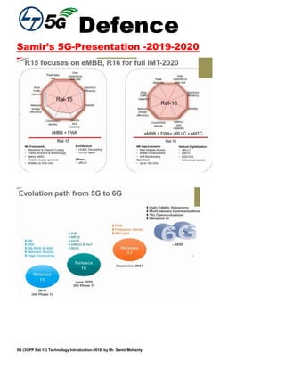
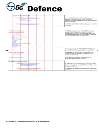
Subscription Permanent Identifier (SUPI)
The SUPI is a globally unique 5G Subscription Permanent Identifier allocated to each subscriber in the
5G System. It is defined in subclause 5.9.2 of 3GPP TS 23.501 [119].
The SUPI may contain:
- an IMSI as defined in subclause 2.1; or
- a NAI as defined in IETF RFC 4282 [53].
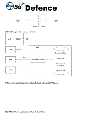
Subscription Concealed Identifier (SUCI)
The SUCI is a privacy preserving identifier containing the concealed SUPI. It is defined in
subclause 6.12.2 of 3GPP TS 33.501 [124].](https://image.slidesharecdn.com/samirswhitepaper5g-200522000255/85/Samir-s-whitepaper5g-109-320.jpg)
![Defence
5G (3GPP Rel.15) Technology Introduction-2018, by Mr. Samir Mohanty
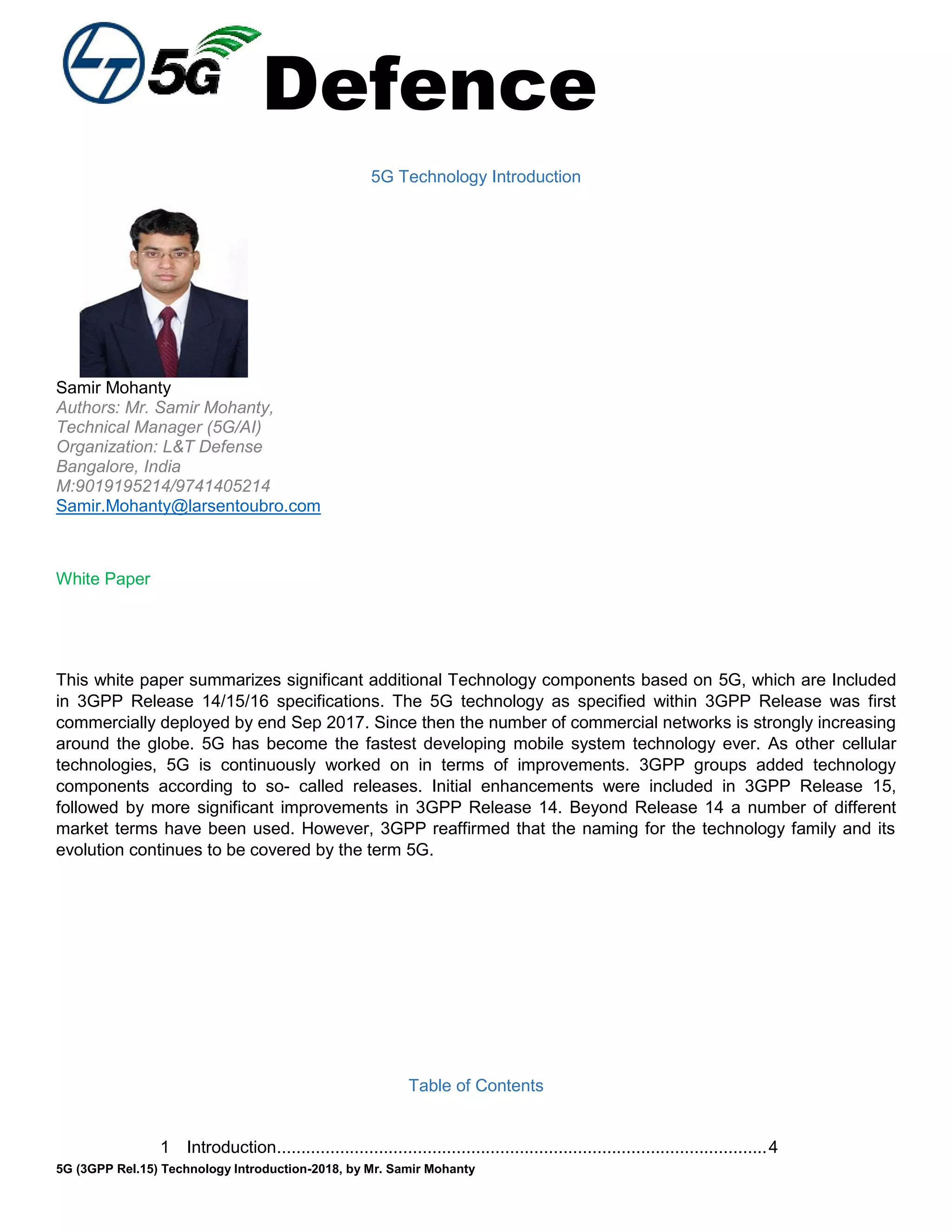
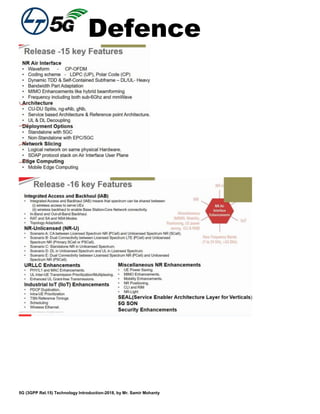
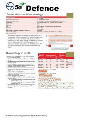
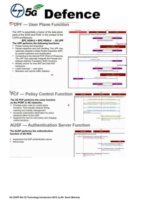
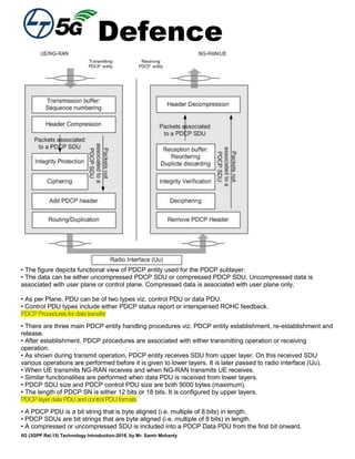
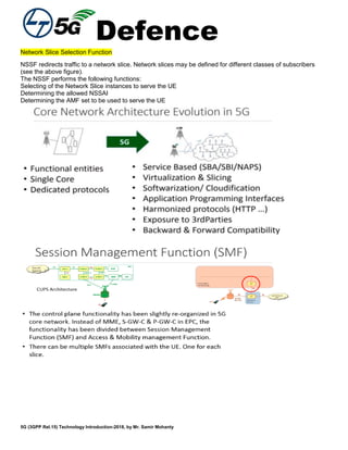
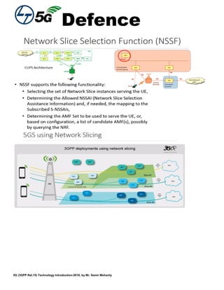
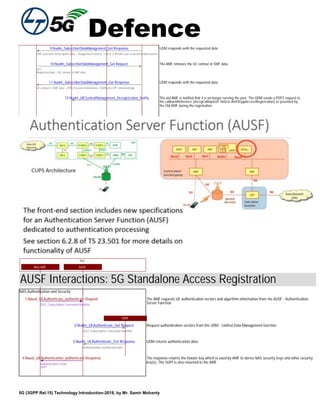
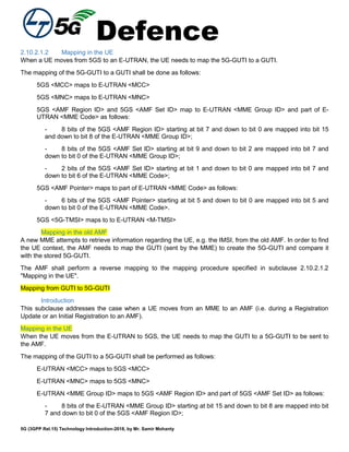
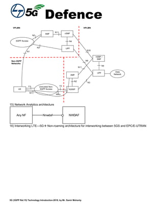
SUCI
Mobile
Country Code
(MCC)
Mobile Network
Code
Routing
Indicator
3 digits 3 digits 4 digits
Protection
Scheme Id
0 - 15 values
Home Network
Public Key Id
FFS
Scheme Output
FFS
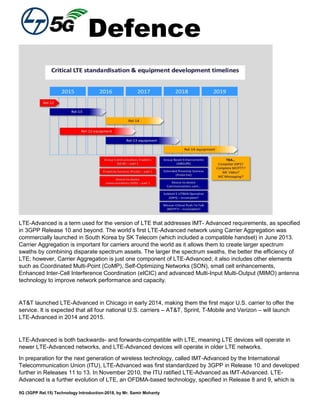
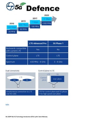
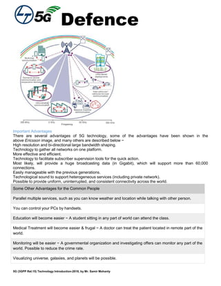
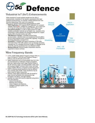
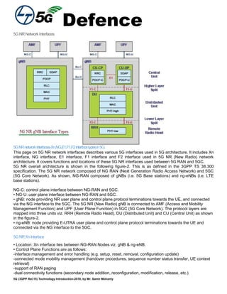
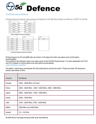
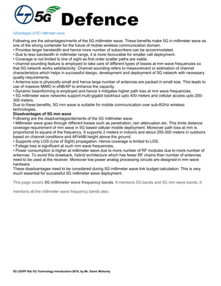
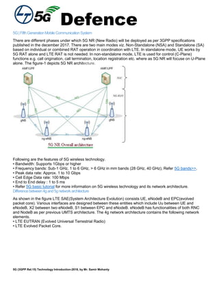
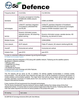
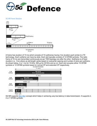
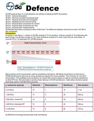
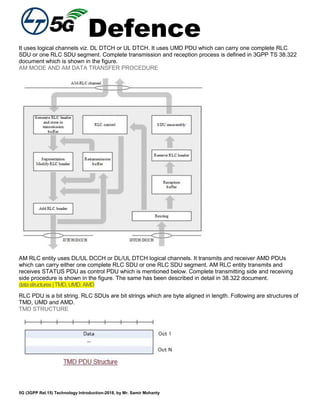
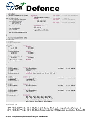
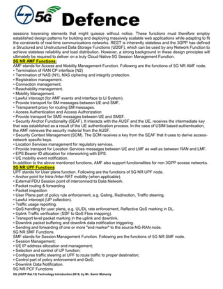
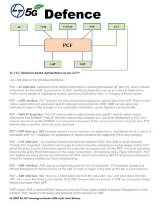
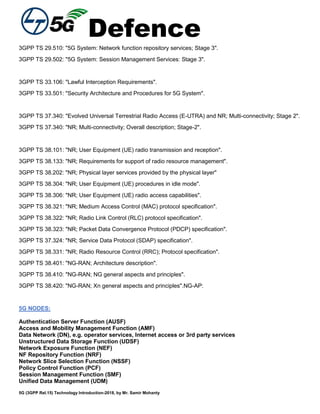
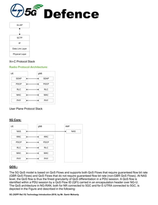
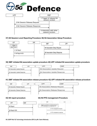
Figure 2.2B-1: Structure of SUCI
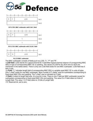
The SUCI is composed of the following parts:
1) Home Network Identifier, composed of two parts:
- Mobile Country Code (MCC), consisting of three decimal digits. The MCC identifies uniquely the
country of domicile of the mobile subscription;
- Mobile Network Code (MNC), consisting of three decimal digits. It contains two or three digits for 3GPP
network applications. The MNC identifies the home PLMN of the mobile subscription. The length of the
MNC (two or three digits) depends on the value of the MCC. A mixture of two and three digit MNC codes
within a single MCC area is not recommended and is outside the scope of this specification. If there are
only 2 significant digits in the MNC, one "0" digit shall be inserted at the left side to fill the 3 digits coding
of MNC;
2) Routing Indicator, consisting of four decimal digits. It contains 1 to 4 digits assigned by the
home network operator and provisioned in the USIM, that allow together with the MCC and MNC to route
network signalling with SUCI to AUSF and UDM instances capable to serve the subscriber. If there are
less than 4 digits in the Routing Indicator, one or more "0" digits shall be inserted at the left side to fill the
4 digits coding of Routing Indicator;
3) Protection Scheme Identifier, consisting in a value in the range of 0 to 15. It represents the null-
scheme or a non-null-scheme specified in Annex C of 3GPP TS 33.501 [124] or a protection scheme
specified by the HPLMN;
4) Home Network Public Key Identifier, consisting of FFS. It represents a public key provisioned by
the HPLMN. In case of null-scheme being used, this data field shall be set to null;
5) Scheme Output, consisting of FFS. It represents the output of a public key protection scheme
specified in Annex C of 3GPP TS 33.501 [124] or a protection scheme specified by the HPLMN.
Editor's Note: the composition of the Protection Scheme Id, Home Network Public Key Id and Scheme
Ouput is FFS.
Editor's note: Examples of SUCI will be described here.
5G Globally Unique Temporary UE Identity (5G-GUTI)
The purpose of the 5G-GUTI is to provide an unambiguous identification of the UE that does not reveal the UE
or the user's permanent identity in the 5G System (5GS). It also allows the identification of the Access and
Mobility Management Function (AMF) and network. It can be used by the network and the UE to establish the
UE's identity during signalling between them in the 5GS. See 3GPP TS 23.501 [119].
The 5G-GUTI has two main components:
- one that identifies the AMF(s) which allocated the 5G-GUTI; and](https://image.slidesharecdn.com/samirswhitepaper5g-200522000255/85/Samir-s-whitepaper5g-110-320.jpg)
![Defence
5G (3GPP Rel.15) Technology Introduction-2018, by Mr. Samir Mohanty
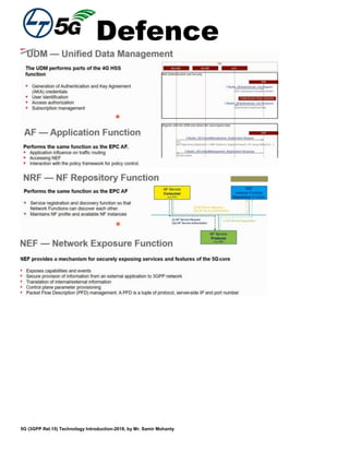
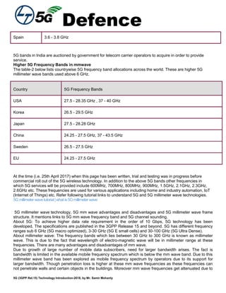
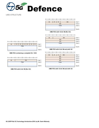
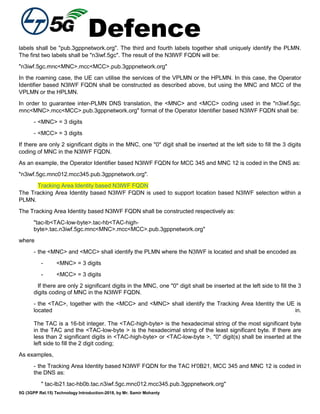
- 8 bits of the E-UTRAN <MME Group ID> starting at bit 7 and down to bit 0 are mapped into bit 9
and down to bit 2 of the 5GS <AMF Set ID>;E-UTRAN <MME Code> maps to 5GS <AMF Set ID> and
5GS <AMF Pointer> as follows:
- 2 bits of the E-UTRAN <MME Code> starting at bit 7 and down to bit 6 are mapped into bit 1
and down to bit 0 of the 5GS <AMF Set ID>;
- 6 bits of the E-UTRAN <MMEC Code> starting at bit 5 and down to bit 0 are mapped into bit 5
and down to bit 0 of the 5GS <AMF Pointer >;
E-UTRAN <M-TMSI> maps to 5GS <5G-TMSI>
Mapping in the new AMF
In order to retrieve the UE's information, e.g. the IMSI, from the old MME, the new AMF shall perform a reverse
mapping to the mapping procedure specified in subclause 2.10.2.2.2 "Mapping in the UE". This is done in
order to be able to include the mapped GUTI in the corresponding message sent to the old MME. The old
MME compares the received GUTI with the stored values for identifying the UE.
Structure of the 5G-S-Temporary Mobile Subscriber Identity (5G-S-TMSI)
The 5G-S-TMSI is the shortened form of the 5G-GUTI to enable more efficient radio signalling procedures (e.g.
paging and Service Request). For paging purposes, the mobile is paged with the 5G-S-TMSI. The 5G-S-TMSI
shall be constructed from the AMF Set ID, the AMF Pointer and the 5G-TMSI:
<5G-S-TMSI> = <AMF Set ID><AMF Pointer><5G-TMSI>
See subclause 2.10.1 for these definitions and subclause 2.10.2 for the mapping
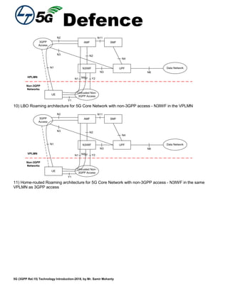
N3IWF FQDN
General
The N3IWF Fully Qualified Domain Name (N3IWF FQDN) shall be constructed using one of the following
formats, as specified in subclause 6.3.6 of 3GPP TS 23.501 [119]:
- Operator Identifier based N3IWF FQDN;
- Tracking Area Identity based N3IWF FQDN;
- the N3IWF FQDN configured in the UE by the HPLMN.
NOTE: The N3IWF FQDN configured in the UE can have a different format than those specified
in the following subclauses.
The Visited Country FQDN for N3IWF is used by a roaming UE to determine whether the visited country
mandates the selection of an N3IWF in this country. The Visited Country FQDN for N3IWF shall be constructed
as specified in subclause 28.3.2.2.4. The Replacement field used in DNS-based Discovery of regulatory
requirements shall be constructed as specified in subclause 28.3.2.2.5.
Editor's note: It is FFS whether N3IWF FQDN for emergency service is supported.
Operator Identifier based N3IWF FQDN
The N3IWF Fully Qualified Domain Name (N3IWF FQDN) contains an Operator Identifier that shall uniquely
identify the PLMN where the N3IWF is located. The N3IWF FQDN is composed of seven labels. The last three](https://image.slidesharecdn.com/samirswhitepaper5g-200522000255/85/Samir-s-whitepaper5g-113-320.jpg)
![Defence
5G (3GPP Rel.15) Technology Introduction-2018, by Mr. Samir Mohanty
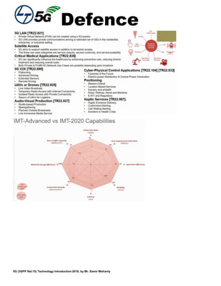
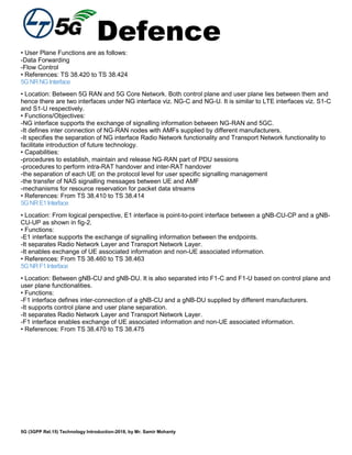
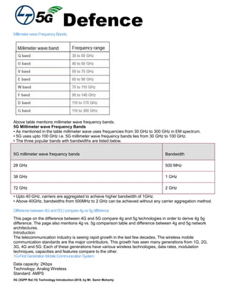
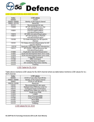
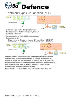
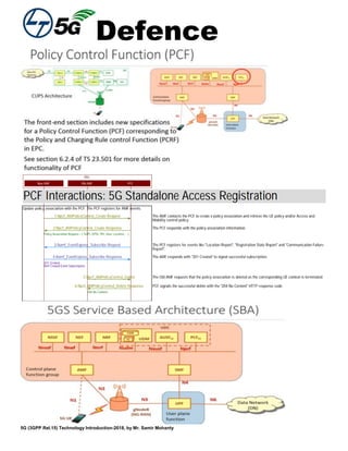
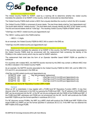
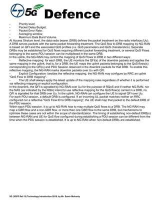
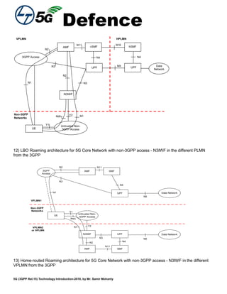
Format of NRF FQDN
The NRF FQDN shall be constructed by prefixing the Home Network Domain Name (see subclause 28.2) of
the PLMN in which the NRF is located with the label "nrf." as described below:
- nrf.5gc.mnc<MNC>.mcc<MCC>.3gppnetwork.org
Network Slice Selection Function (NSSF) FQDN
28.3.2.4.1 General
For roaming service, the vNSSF may invoke the Nnssf_NSSelection_Get service operation from the hNSSF.
For routing of the HTTP/2 messages across the PLMN, the vNSSF self-constructs the FQDN of the hNSSF as
per the format specified in subclause 28.3.2.4.2. The Home Network is identified by the PLMN ID of the SUPI
provided to the vNSSF by the NF Service Consumer (e.g. the AMF).
28.3.2.4.2 Format of NSSF FQDN
The NSSF FQDN shall be constructed by prefixing its Home Network Domain Name (see subclause 28.2) with
the label "nssf." as described below:
- nssf.5gc.mnc<MNC>.mcc<MCC>.3gppnetwork.org
28.3.2.5 AMF Name
The AMF Name FQDN shall uniquely identify an AMF.
The AMF Name FQDN shall be constructed as:
"<AMF-id>.amf.5gc.mnc<MNC>.mcc<MCC>.3gppnetwork.org"
where
- the <MNC> and <MCC> shall identify the PLMN where the AMF is located and shall be encoded as
- <MNC> = 3 digits
- <MCC> = 3 digits
If there are only 2 significant digits in the MNC, one "0" digit shall be inserted at the left side to fill the 3
digits coding of MNC in the AMF Name FQDN.
- the <AMF-id> shall contain at least one label.
As example,
- If <AMF-id> is amf1.cluster1.net2, the AMF Name FQDN for MCC 345 and MNC 12 as:
"amf1.cluster1.net2.amf.5gc.mnc012.mcc345.3gppnetwork.org"
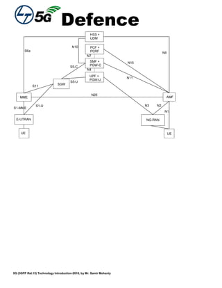
Information for Network Slicing
General
In order to identify a Network Slice end to end, the 5GS uses information called S-NSSAI (Single Network Slice
Selection Assistance Information). See subclause 5.15.2 of 3GPP TS 23.501 [119].
An S-NSSAI is comprised of:
- A Slice/Service type (SST),](https://image.slidesharecdn.com/samirswhitepaper5g-200522000255/85/Samir-s-whitepaper5g-116-320.jpg)
![Defence
5G (3GPP Rel.15) Technology Introduction-2018, by Mr. Samir Mohanty
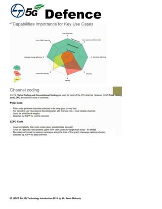
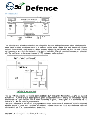
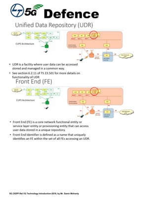
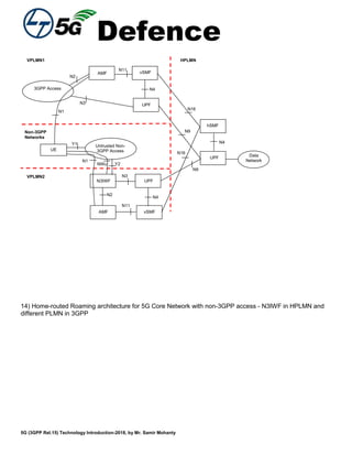
- A Slice Differentiator (SD), which is optional information that complements the Slice/Service type(s) to
differentiate amongst multiple Network Slices.
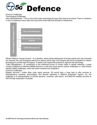
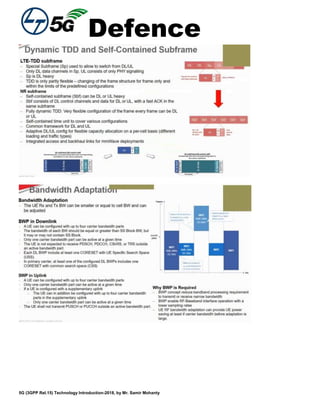
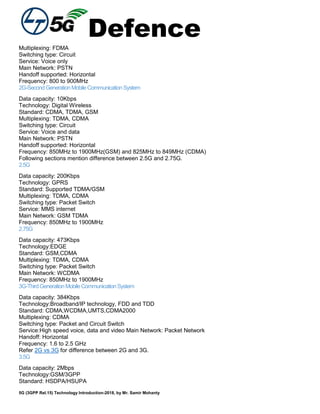
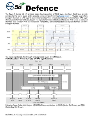
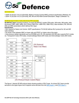
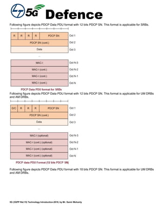
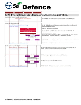
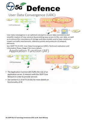
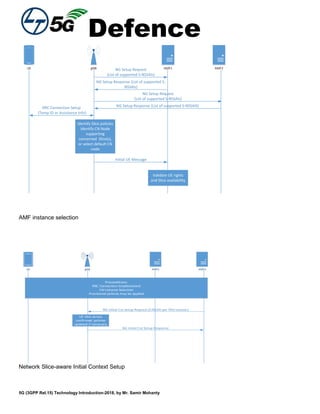
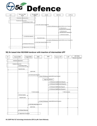
Format of the S-NSSAI
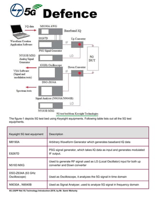
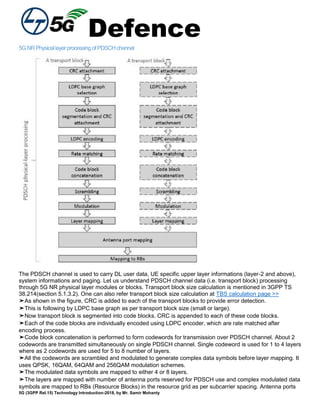
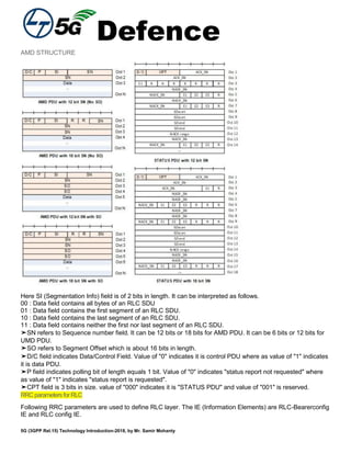
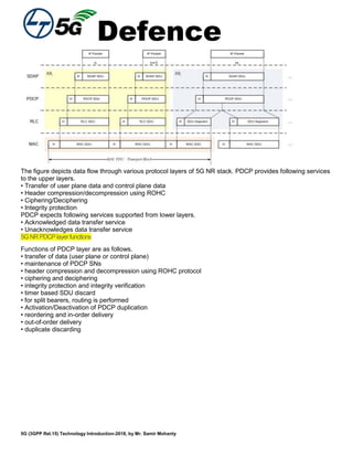
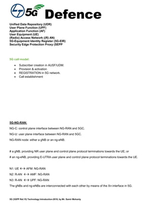
The structure of the S-NSSAI is depicted in Figure 28.4.2-1
24 bits
S-NSSAI
8 bits
SST SD
Figure 28.4.2-1: Structure of S-NSSAI
The S-NSSAI may include both the SST and SD fields (in which case the S-NSSAI length is 32 bits in total), or
the S-NSSAI may just include the SST field (in which case the S-NSSAI length is 8 bits only).
The SST field may have standardized and non-standardized values. Values 0 to 127 belong to the
standardized SST range and they are defined in 3GPP TS 23.501 [119]. Values 128 to 255 belong to the
Operator-specific range.
NF FQDN Format for Inter PLMN Routing
For routing HTTP/2 request messages to NF in a different PLMN, the FQDN of the target NF shall have the
Home Network Domain (see subclause 28.2) as the trailing part.
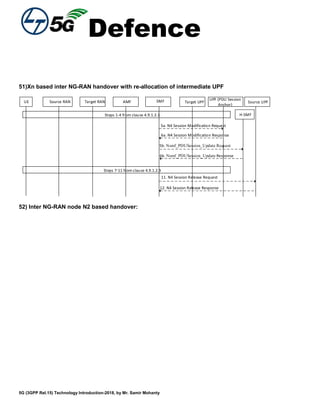
Summary:
LTE-Advanced Pro brings great enhancements in Radio performance on top of LTE-Advanced with Multi-Gbps
data rates, higher spectral efficiency and one-way latency below 1 ms. LTE-Advanced Pro also enables a
number of new application scenarios, including IOT optimization for the programmable world, vehicular
connectivity and public safety. LTE-Advanced Pro is supported by new features in 3GPP Release 14 and 5G is
supported in 3GPP Release 15.](https://image.slidesharecdn.com/samirswhitepaper5g-200522000255/85/Samir-s-whitepaper5g-117-320.jpg)
![Defence
5G (3GPP Rel.15) Technology Introduction-2018, by Mr. Samir Mohanty
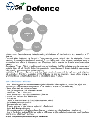
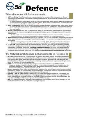
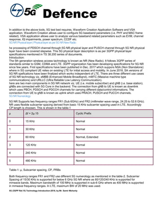
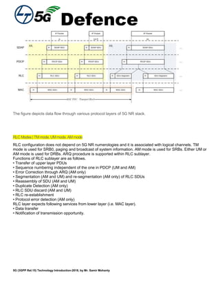
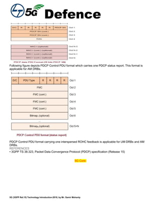
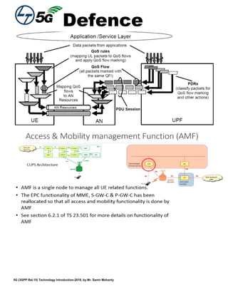
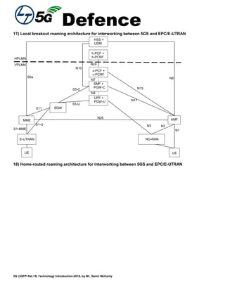
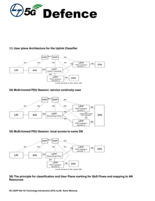
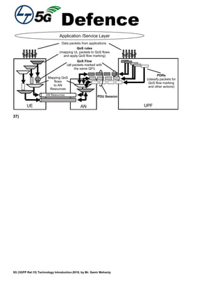
- For each UE, 5GC establishes one or more PDU Sessions;
- For each UE, the NG-RAN establishes one or more Data Radio Bearers (DRB) per PDU Session. The
NG-RAN maps packets belonging to different PDU sessions to different DRBs. Hence, the NG-RAN
establishes at least one default DRB for each PDU Session;
- NAS level packet filters in the UE and in the 5GC associate UL and DL packets with QoS Flows;
- AS-level mapping rules in the UE and in the NG-RAN associate UL and DL QoS Flows with DRBs.
UPFNBUE
PDU Session
Radio NG-U
NG-RAN 5GC
Radio Bearer NG-U Tunnel
QoS Flow
QoS Flow
Radio Bearer
QoS Flow
NG-RAN and 5GC ensure quality of service (e.g. reliability and target delay) by mapping packets to
appropriate QoS Flows and DRBs. Hence there is a 2-step mapping of IP-flows to QoS flows (NAS) and from
QoS flows to DRBs (Access Stratum).
At NAS level, a QoS flow is characterised by a QoS profile provided by 5GC to NG-RAN and QoS rule(s)
provided by 5GC to the UE. The QoS profile is used by NG-RAN to determine the treatment on the radio
interface while the QoS rules dictates the mapping between uplink User Plane traffic and QoS flows to the UE.
A QoS flow may either be "GBR" or "Non-GBR" depending on its profile. The QoS profile of a QoS flow
contains QoS parameters, for instance (see 3GPP TS 23.501 [3]):
- For each QoS flow:
- A 5G QoS Identifier (5QI);
- An Allocation and Retention Priority (ARP).
- In case of a GBR QoS flow only:
- Guaranteed Flow Bit Rate (GFBR) for both uplink and downlink;
- Maximum Flow Bit Rate (MFBR) for both uplink and downlink;
- Maximum Packet Loss Rate for both uplink and downlink.
- In case of Non-GBR QoS only:
- Reflective QoS Attribute (RQA): the RQA, when included, indicates that some (not necessarily all)
traffic carried on this QoS flow is subject to reflective quality of service (RQoS) at NAS.
In addition, an Aggregate Maximum Bit Rate is associated to each PDU session (Session-AMBR) and to each
UE (UE-AMBR). The Session-AMBR limits the aggregate bit rate that can be expected to be provided across
all Non-GBR QoS Flows for a specific PDU Session. The UE-AMBR limits the aggregate bit rate that can be
expected to be provided across all Non-GBR QoS Flows of a UE.
The 5QI is associated to QoS characteristics giving guidelines for setting node specific parameters for each
QoS Flow. Standardized or pre-configured 5G QoS characteristics are derived from the 5QI value and are not
explicitely signalled. Signalled QoS characteristics are included as part of the QoS profile. The QoS
characteristics consist for instance of (see 3GPP TS 23.501 [3]):
- Resource Type (GBR, delay critical GBR or Non-GBR);](https://image.slidesharecdn.com/samirswhitepaper5g-200522000255/85/Samir-s-whitepaper5g-124-320.jpg)
![Defence
5G (3GPP Rel.15) Technology Introduction-2018, by Mr. Samir Mohanty
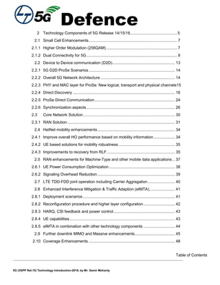
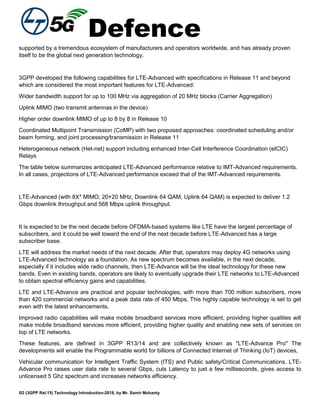
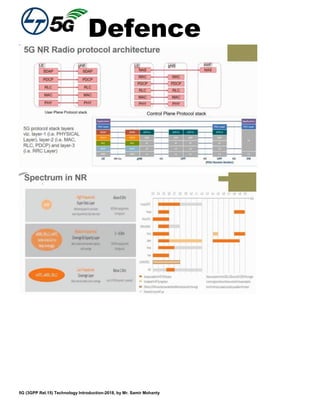
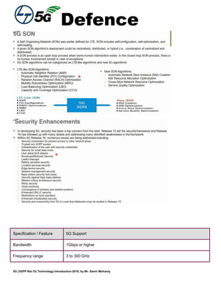
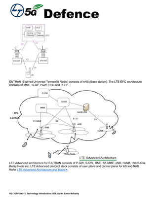
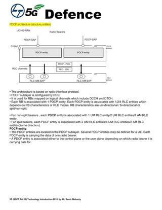
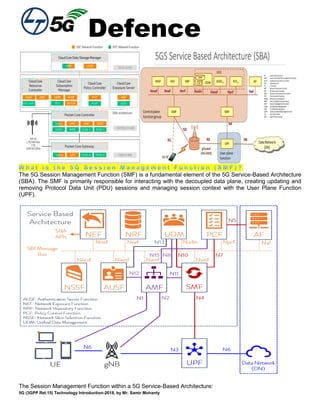
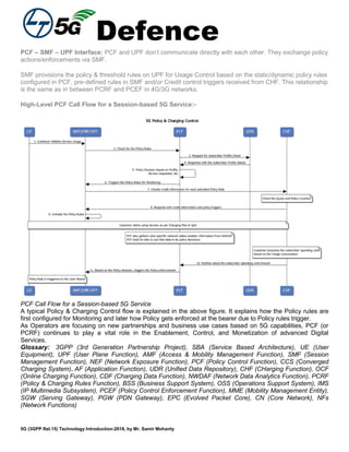
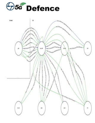
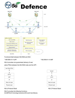
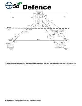
1. NG-C: PDU session establishment req [NAS message]
5. NG-C: PDU session establishment ACK
AMFUE gNB UPF
2. RRC: DRB setup Req
[DRB parameters, NAS message]
4. RRC DRB setup complete
6. PDU data tunnel [QFI]6. User plane data over DRB [QFI]
3. UE establishes DRB
PDU session establishment
N4: UPF SMF: NG-AP
N5: PCF AF (IMS): diameter
N6: UPF DATA NETWORK
N7: SMF PCF: DIAMETER
N7r: hPCF vPCF: DIAMETER
N8: AMF UDM: DIAMETER
N9: UPF UPF: NG-AP
N10: SMF UDM
N11: AMF SMF
N12: AMF AUSF
N13: AUSF UDM
N14: AMF AMF
N15: AMF PCF
N16: vSMF hSMF
N22: AMF NSSF
N24: vPCF hPCF
N26: MME AMF
N31: vNSSF hNSSF
5G: Call Flow-](https://image.slidesharecdn.com/samirswhitepaper5g-200522000255/85/Samir-s-whitepaper5g-128-320.jpg)
![Defence
5G (3GPP Rel.15) Technology Introduction-2018, by Mr. Samir Mohanty
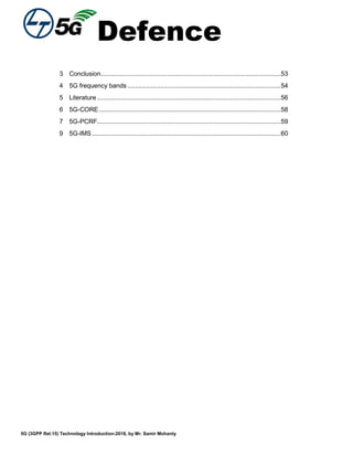
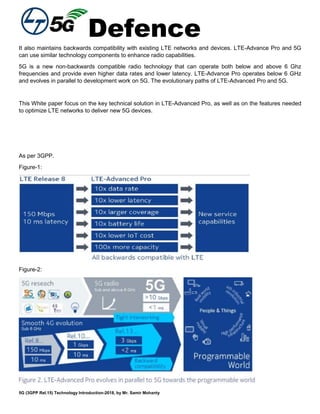
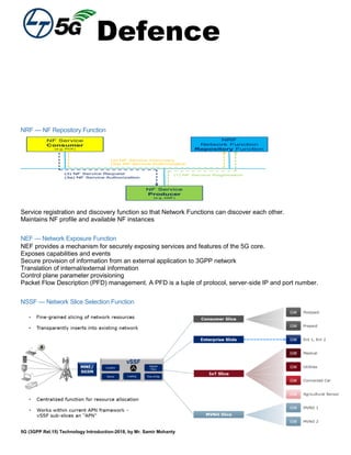
5QI
Value
Resource
Type
Default
Priority
Level
Packet
Delay
Budget
Packet
Error
Rate
Default
Maximum
Data Burst
Volume
(NOTE 2)
Default
Averaging
Window
Example Services
10 Delay
Critical
GBR
11 5 ms 10-5
160 B TBD Remote control
(see TS 22.261 [2])
11
NOTE 4
12 10 ms
NOTE 5
10-5
320 B TBD Intelligent transport
systems
12 13 20 ms 10-5
640 B TBD
16
NOTE 4
18 10 ms 10-4
255 B TBD Discrete
Automation
17
NOTE 4
19 10 ms 10-4
1358 B
NOTE 3
TBD Discrete
Automation
1
GBR
NOTE 1
20 100 ms 10-2
N/A TBD Conversational
Voice
2 40 150 ms 10-3
N/A TBD Conversational
Video (Live
Streaming)
3 30 50 ms 10-3
N/A TBD Real Time Gaming,
V2X messages
Electricity
distribution –
medium voltage,
Process automation
- monitoring
4 50 300 ms 10-6
N/A TBD Non-Conversational
Video (Buffered
Streaming)
65 7 75 ms
10-2
N/A TBD Mission Critical user
plane Push To Talk
voice (e.g., MCPTT)
66
20
100 ms
10-2
N/A TBD Non-Mission-Critical
user plane Push To
Talk voice
75 25 50 ms 10-2
N/A TBD V2X messages
E
NOTE 4
18 10 ms 10-4
255 B TBD Discrete
Automation
F
NOTE 4
19 10 ms 10-4
1358 B
NOTE 3
TBD Discrete
Automation
5 Non-GBR
NOTE 1
10 100 ms 10-6
N/A N/A IMS Signalling
6
60 300 ms 10-6
N/A N/A Video (Buffered
Streaming)
TCP-based (e.g.,
www, e-mail, chat,
ftp, p2p file sharing,
progressive video,
etc.)
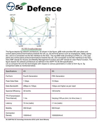
7 N/A N/A Voice,](https://image.slidesharecdn.com/samirswhitepaper5g-200522000255/85/Samir-s-whitepaper5g-149-320.jpg)
![Defence
5G (3GPP Rel.15) Technology Introduction-2018, by Mr. Samir Mohanty
70 100 ms 10-3
Video (Live
Streaming)
Interactive Gaming
8
80 300 ms
10-6
N/A N/A
Video (Buffered
Streaming)
TCP-based (e.g.,
www, e-mail, chat,
ftp, p2p file
9 90 N/A N/A sharing,
progressive video,
etc.)
69 5 60 ms 10-6
N/A N/A Mission Critical
delay sensitive
signalling (e.g., MC-
PTT signalling)
70 55 200 ms 10-6
N/A N/A Mission Critical
Data (e.g. example
services are the
same as QCI 6/8/9)
79 65 50 ms 10-2
N/A N/A V2X messages
80 66 10 ms 10-6
N/A N/A Low Latency eMBB
applications
Augmented Reality
NOTE 1: a packet which is delayed more than PDB is not counted as lost, thus not included in the
PER.
NOTE 2: it is required that default Maximum Data Burst Volume is supported by a PLMN supporting
the related 5QIs.
NOTE 3: This Maximum Burst Size value is intended to avoid IP fragmentation on an IPv6 based,
IPSec protected, GTP tunnel to the 5G-AN node.
NOTE 4: A delay of 1 ms for the delay between a UPF terminating N6 and a 5G-AN should be
subtracted from a given PDB to derive the packet delay budget that applies to the radio
interface.
NOTE 5:The jitter for this service is assumed to be 20 msec as per TS 22.261 [2].](https://image.slidesharecdn.com/samirswhitepaper5g-200522000255/85/Samir-s-whitepaper5g-150-320.jpg)
![Defence
5G (3GPP Rel.15) Technology Introduction-2018, by Mr. Samir Mohanty
UE eNodeB- -New MME
Old MME/SGSN/
AMF -Serving GW SMF +
PGW-C
UPF +
PGW-U
. 1. Attach Request
3. Create Session Response
PCF +
PCRF
UDM +
HSS
2. E-UTRAN Attach Figure 5.3.2-1 in TS 23.401 [13] Steps 2 to 14
4. E-UTRAN Attach Figure 5.3.2-1 in TS 23.401 [13] Steps 16 to 17
5 . RRC Connection Reconfiguration or
RRC Direct Transfer
6. E-UTRAN Attach Figure 5.3.2-1 in TS 23.401 [13] Steps 19 onwards
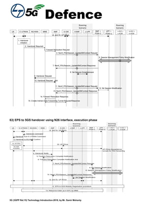
69) Mobility procedure from 5GS to EPS without N26 interface
11. Notify Request
12. Notify Response
0. UE is registered in 5GS
t
4. TAU Reject
5. Attach Request
6. Attach Request
9. Update Location Ack
NG RAN
new
MME
SGW
PGW-C+
SMFeNodeB
PGW-U+
UPF
UE
HSS+
UDM
1.Trigger to
startTAU
procedure
8. Update Location Request
old
AMF
2. TAU Request
3. TAU Reques
7. E-UTRAN Initial Attach Figure 5.3.2.-1, Steps 4-7, in TS 23.401
-24, in TS 23.401[x]10. E-UTRAN Initial Attach Figure 5.3.2.-1, Steps 12
14. PGW-C+SMF initiates release for transferred PDU Session
13. UE requested PDN Connectivity
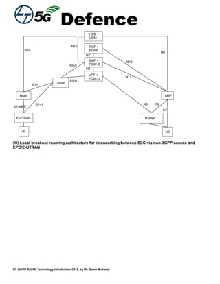
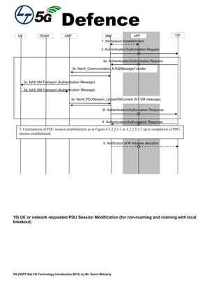
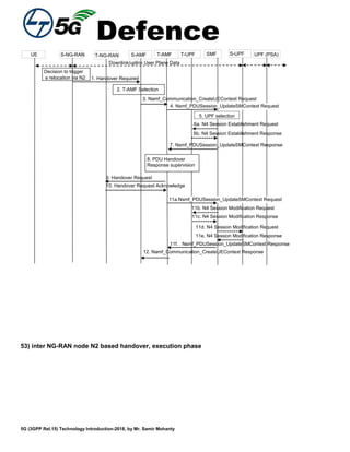
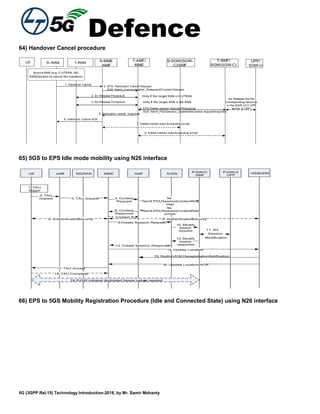
70) Deregistration procedure for untrusted non-3gpp access](https://image.slidesharecdn.com/samirswhitepaper5g-200522000255/85/Samir-s-whitepaper5g-185-320.jpg)
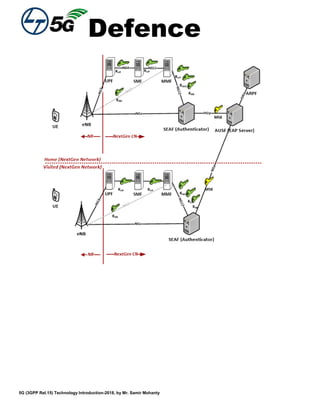

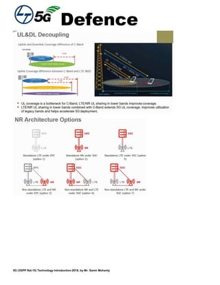
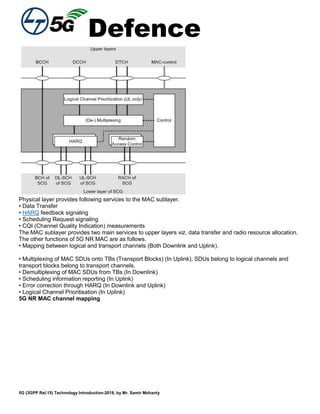
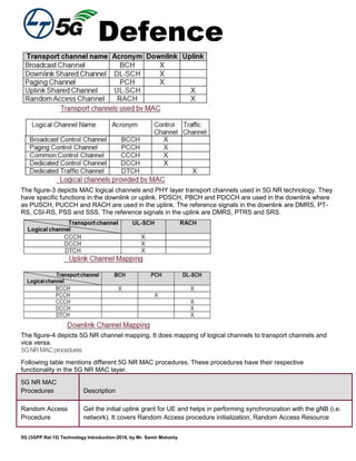
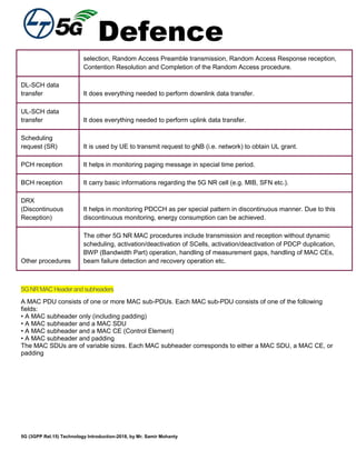
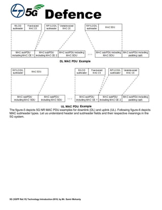
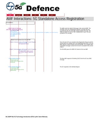
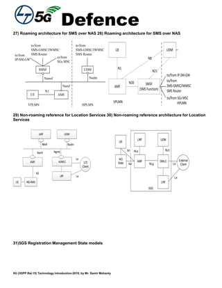
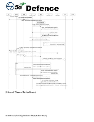
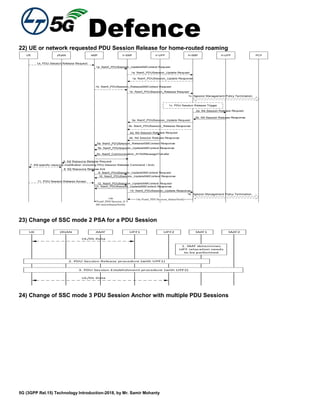
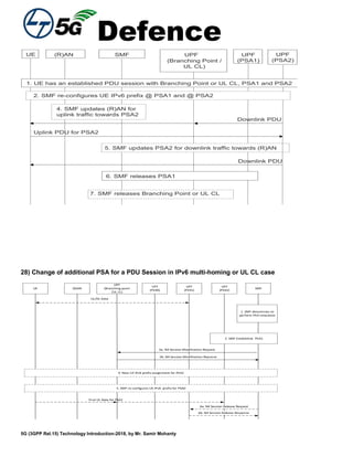
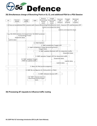
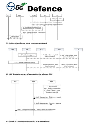
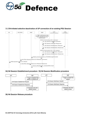
This white paper summarizes 5G technology components included in 3GPP Release 14, 15 and 16 specifications. Key technologies discussed include small cell enhancements, device-to-device communication, network solutions, mobility enhancements, machine communications, and coverage enhancements. 5G aims to support higher data rates, lower latency, and more connected devices compared to previous standards. However, challenges remain regarding interference management, efficient medium access control, and optimizing 5G for both human and machine traffic.


