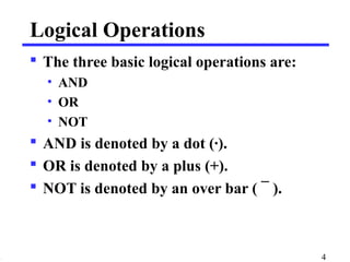
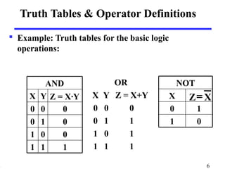
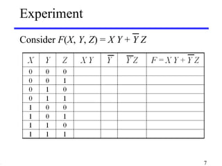
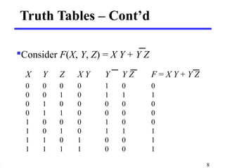
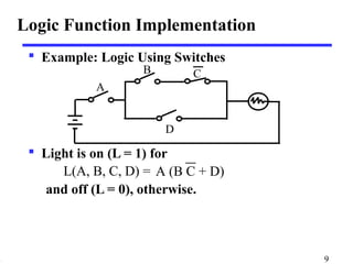
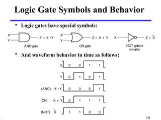
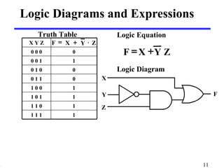
3. Logic and Gates
Basic logical operators are the logic functions
AND, OR and NOT.
Logic gates implement logic functions.
Boolean Algebra: a useful mathematical system
for specifying and transforming logic functions
to designing and analyzing digital systems!
3
4. Logical Operations
The three basic logical operations are:
• AND
• OR
• NOT
AND is denoted by a dot (·).
OR is denoted by a plus (+).
NOT is denoted by an over bar ( ¯ ).
4
5. Notation Examples
Examples:
• Y = A× B
is read “Y is equal to A AND B.”
• z = x + y
is read “z is equal to x OR y.”
• X = A
is read “X is equal to NOT A.”
• 1 + 1 = 2
(read “one plus one equals two”)
• 1 + 1 = 1
(read “1 or 1 equals 1”).
5
6. Truth Tables & Operator Definitions
X
NOT
Z= X
0 1
1 0
Example: Truth tables for the basic logic
operations:
AND OR
X Y Z = X·Y
0 0 0
0 1 0
1 0 0
1 1 1
X Y Z = X+Y
0 0 0
0 1 1
1 0 1
1 1 1
6
8. Truth Tables – Cont’d
Consider F(X, Y, Z) = X Y + Y Z
X Y Z X Y Y Y Z F = X Y + Y Z
0 0 0 0 1 0 0
0 0 1 0 1 1 1
0 1 0 0 0 0 0
0 1 1 0 0 0 0
1 0 0 0 1 0 0
1 0 1 0 1 1 1
1 1 0 1 0 0 1
1 1 1 1 0 0 1
8
9. Logic Function Implementation
Example: Logic Using Switches
B
A
D
Light is on (L = 1) for
C
L(A, B, C, D) =
and off (L = 0), otherwise.
A (B C + D)
9
10. Logic Gate Symbols and Behavior
Logic gates have special symbols:
OR gate
X
Y
Z = X + Y
And waveform behavior in time as follows:
X 0 0 1 1
Y 0 1 0 1
(AND) X · Y 0 0 0 1
(OR) X + Y 0 1 1 1
(NOT) X 1 1 0 0
X
Y
Z = X · Y
AND gate
X Z = X
NOT gate or
inverter
10
11. Logic Diagrams and Expressions
X
Logic Equation
F = X + Y Z
Logic Diagram
Y F
Z
Truth Table
X Y Z F = X + Y × Z
0 0 0 0
0 0 1 1
0 1 0 0
0 1 1 0
1 0 0 1
1 0 1 1
1 1 0 1
1 1 1 1
11