Gfe Mayur Vihar Call Girls Service WhatsApp -> 9999965857 Available 24x7 ^ De...
Chapter 4 logic design
1. CHAPTER 4 – LOGIC DESIGN
4.1 Introduction
Logic circuits are the basis for modern digital computer systems. To appreciate
how computer systems operate, there is a need to understand digital logic and Boolean
algebra. Also, Boolean logic forms the basis for computation in computer systems.
4.2 Binary Logic
Binary logic deals with variables and take on two discrete values and with operations that
assume logical meaning. Binary logic consists of binary variables and a set of logical operations.
The variables are designated by letters of the alphabet, such as A, B, C, x, y, z, etc. with each
variable having two and only two distinct values: 1 and 0.
There are three basic logical operations: AND, OR, and NOT
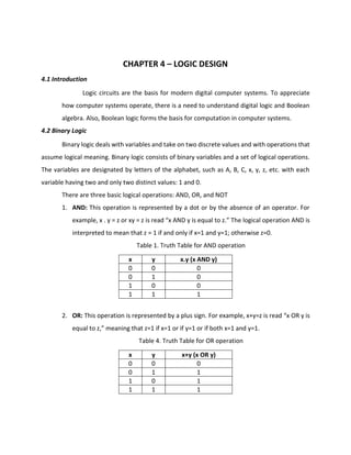
1. AND: This operation is represented by a dot or by the absence of an operator. For
example, x . y = z or xy = z is read “x AND y is equal to z.” The logical operation AND is
interpreted to mean that z = 1 if and only if x=1 and y=1; otherwise z=0.
Table 1. Truth Table for AND operation
x y x.y (x AND y)
0 0 0
0 1 0
1 0 0
1 1 1
2. OR: This operation is represented by a plus sign. For example, x+y=z is read “x OR y is
equal to z,” meaning that z=1 if x=1 or if y=1 or if both x=1 and y=1.
Table 4. Truth Table for OR operation
x y x+y (x OR y)
0 0 0
0 1 1
1 0 1
1 1 1
2. 3. NOT: This operation is represented by a prime (sometimes by an overbar). For
example, x’=z is read “not x is equal to z,” meaning that z is what x is not.
Table 3. Truth Table for NOT operation
x x’ (NOT x)
0 1
1 0
4.3 Logic Gates
Logic gates are electronic circuits that operate on one or more input signals to
produce an output signal.
ANDGate(Q=AB)
ORGate(Q=A+B)
NOTGate(Inverter) (Q = A’)
NANDGate(Q=(AB)’)
4. F = (x+y’)(xy)’
Using LOGISM
Logisim is a digital design tool for educational purposes designed by Carl Burch of Hendrix
University. Logisim can be used for the logical design of circuits and is the tool you will be using
for the FIT design projects.
Environment Layout
Toolbar: The toolbar contains short cuts to several commonly used items
o The poke tool (shaped like a hand) is used to alter input pins.
o The input pin (green circle surrounded by a box) is used to send a signal through a
wire. When placing the input on the canvas it initializes to 1-bit. This number of
bits can be increased in the Attribute Table.
5. o The output pin (green circle in a circle) is used to observe output from a gate. The
output pin toggles in real time as long as the simulation is enabled from the menu
bar Simulate > Simulate enabled
Explorer Pane: The list of wiring, gates, multiplexers, etc... that are available for digital
design in Logisim. Please note not all items are allowed to be used in every project.
Attribute Table: Gives detailed attributes of digital design components (e.g., AND, OR,
XOR gates). The attribute table allows you to alter the number of inputs/outputs that a
digital design component.
Canvas: The canvas is the area for you to create your digital circuits. In the canvas area
you may simulate your circuits while designing in real time.
4.4 Boolean Functions and Truth Tables
Boolean algebra is an algebra that deals with binary variables and logic operations. A
Boolean function described by an algebraic expression consists of binary variables, the constants
0 and 1, and the logic operation symbols. As an example, consider the Boolean function
F1 = x + y’ z
The function F1 is equal to 1 if x is equal to 1 or if both y’ and z are equal to 1.
A Boolean function can be represented in a truth table.
X Y Z Y’ Y’Z F1=X+Y’Z
1 1 1 0 0 1
1 1 0 0 0 1
1 0 1 1 1 1
1 0 0 1 0 1
0 1 1 0 0 0
0 1 0 0 0 0
0 0 1 1 1 1
0 0 0 1 0 0
6. 4.5 Boolean Algebra
Boolean algebra is a deductive mathematical system closed over the values zero
and one. Boolean algebra is a set of rules formulated by the English mathematician
George Boole that describe certain propositions whose outcome would either true or
false. With regard to digital logic, these rules are used to described circuits whose state
can be either 1 (true) or 0 (false).
Properties or Postulates of Boolean Algebra:
1. Closure: The Boolean system is closed with respect to a binary operator that if for
every pair of Boolean values, it produces a Boolean result.
2. Commutativity: A binary operator ( . or +) is said to be commutative if (A.B = B.A) or
(A+B) = (B+A) for all possible Boolean Values A and B.
3. Associativity: A binary operator is said to be associative if (A.B). C = A.(B.C) or (A+B)+C
= A+(B+C) for all possible Boolean values A, B, and C.
4. Distribution: Two binary operators, . and + are distributive if A. (B+C) = (A.B)+(A.C) or
A+(B.C) = (A+B). (A+C) for all possible values A, B, and C.
5. Identity: A Boolean value is said to be identity element with respect to some binary
operator. (A+0=A, A+1=1, A.0=0, and A.1=A)
6. Complement: The complement property says that any value AND (.) the complement
of that value is always equal to zero (0) (A.A’=0) or any value OR (+) the complement
of that value is always equal to one (1) (A+A’=1).
7. De Morgan’s Law: De Morgan’s Law says that the complement of A AND B (A.B)’ is the
same as the complement of A OR the complement of B (A’+B’) or the complement of
A OR B (A+B)’ is the same as the complement of A AND the complement of B (A’.B’).
Boolean Algebra Summary
Operations with 0 and 1:
1. X + 0 = X X.1 = X
2. X + 1 = 1 X.0 = 0
Idempotent laws:
3. X + X = X X.X (XX) = X
7. Involution law:
4. (X’)’ = X
Laws of complementarity:
5. X + X’ = 1 X.X’(XX’) = 0
Commutative laws:
X + X’ = 1 X .X’ = 0
Absorption Laws:
X + XY = X X.(X+Y) = X
X+XY = X.1 + XY X.(X+Y) = (X+0).(X+Y)
= X(1+Y) =X+(0.Y)
= X(1) =X+0
= X =X
x + x’ · y = x + y
Proof:
x + x’ · y
= (x + x’) · (x + y)
= 1 · (x + y)
= x + y
x · (x’ + y) = x · y
Proof:
x · (x’ + y)
= x · x’ + x · y
= 0 + x · y
= x · y
x · y + x · y’ = x
Proof:
x · y + x · y’
= x · (y + y’)
= x · 1
= x
(x + y) · (x + y’) = x
Proof:
(x + y) · (x + y’)
= x + (y · y’)
= x + 0
= x
8. Exercises:
1. Using Logisim, draw the logic diagrams of the following expressions:
1.1 F = (X+Y)(X’Y’)
1.2 F = ((XY)(X+Y))’
1.3 F = ((X+Y’)(Y+Z’)) + (X’+Z)
2. List and complete the truth table of the following Boolean functions:
2.1 F = xy+xy’+y’z
2.2 F= x’z’+yz
3. Using Logisim, draw the logic diagrams of the circuits that implement the Boolean
functions in Problem #4.
4. Using Boolean Algebra, simplify the following Boolean expressions:
4.1 xy+x’y
4.2 (x+y)(x’+y)
4.3 xyz+x’y+xyz’
4.4 (A+B)’(A’+B)’
5. Using Logisim, draw the logic diagrams of the circuits that implement the original and
simplified expressions in Problem #4.
References:
Mano, Morris M. and Michael D. Ciletti. (2007). Digital Design Fourth Edision. New Jersey:
Pearson – Prentice Hall.
Leon, Alexis and Mathews Leon. (1999). Introduction to Computers. Chennai: Leon Press.
Basic Gates and Functions. Retrieved from http://www.ee.surrey.ac.uk/Projects/CAL/digital-
logic/gatesfunc/
Logic Circuits, Boolean Algebra, and Truth Tables. Retrieved from
https://drstienecker.com/tech-332/3-logic-circuits-boolean-algebra-and-truth-tables/