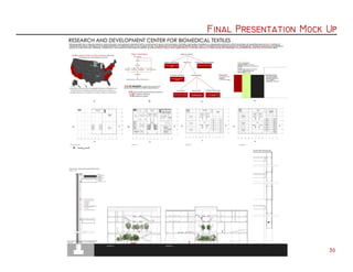
The document provides an overview of the design process for a Biomedical Textile Development & Research Center located in Minneapolis, Minnesota. It includes sections on site selection, program development, facade design, structural system, atrium design, mechanical systems, and presentation materials. Key aspects include replacing the existing failing exterior structure with a steel diagrid system to provide rigidity and transparency, designing the facade to "wrap" around the building with varying transparency panels, and including a central atrium space to connect program areas and promote collaboration.
Passive Solar Design (Architecture)
The intention of this slideshow is to provide a basic introduction to passive solar design and architecture.
A very simple historical example (Afghanistan) is given with some diagrams to explain the basics of passive solar and some passive ventilation principles (comparing winter and summer). Towards the end an example of a more complex design (Solar decathlon 2012-SLIDE house, Egypt) is included to illustrate some of the combination of solar principles and movement in relation to the sun (harvesting the energy of the sun). On some of the last slides I make a comment about the SLIDE house to
get the viewer to think about Nano technology and bio-mimetics. The last slide provide a link to a website on Bio-mimetics.
The viewer can explore bio-mimicry and its role in design by asking nature how?
Website: http://williamvanzyldvchc.co.nz/
Expert Accessory Dwelling Unit (ADU) Drafting ServicesResDraft
Whether you’re looking to create a guest house, a rental unit, or a private retreat, our experienced team will design a space that complements your existing home and maximizes your investment. We provide personalized, comprehensive expert accessory dwelling unit (ADU)drafting solutions tailored to your needs, ensuring a seamless process from concept to completion.
Hello everyone! I am thrilled to present my latest portfolio on LinkedIn, marking the culmination of my architectural journey thus far. Over the span of five years, I've been fortunate to acquire a wealth of knowledge under the guidance of esteemed professors and industry mentors. From rigorous academic pursuits to practical engagements, each experience has contributed to my growth and refinement as an architecture student. This portfolio not only showcases my projects but also underscores my attention to detail and to innovative architecture as a profession.
You could be a professional graphic designer and still make mistakes. There is always the possibility of human error. On the other hand if you’re not a designer, the chances of making some common graphic design mistakes are even higher. Because you don’t know what you don’t know. That’s where this blog comes in. To make your job easier and help you create better designs, we have put together a list of common graphic design mistakes that you need to avoid.
1. Biomedical Textile Development & Research Center
Steph Dudak & Mina Bellare | Fall 2015 | Design VIII | Professor Matthew Gindlesparger
2.
3. Table of Contents
Minneapolis, MN Demographics 01
St. Anthony Falls 02
Site Selection 03
Medical Textiles 04
Program Mock Up 05
Mid Crit Presentation 06
Plans 07
Sefaira Analyses 09
Facade Development 11
Wall Sections 17
Atrium Development 19
Mechanical Systems 25
Plumbing 27
Occupancy Loads 28
Final Presentation Mock Up & Other
Development 29
1/4" Final Model 33
1/32" Final Model 35
Final Presentation 36
Final Boards 37
8. Program Mock Up
05
The following two
boards were developed within
three days of each other.
While we continue to
bring in basic demographic
and site information in to
these presentations, the
focus for the board to
the right is mainly on plan
organization and massing.
9. Mid Crit Board
06
The board for our mid crit features more definitive plan organization, site location, and bioclimatic strategies at the
time. At this stage, however, we did not have much of an attitude about the exterior of the building and what it really should
be. We had an idea of peeling away the existing facade but it was not executed in a way that we felt displayed our intentions
about a biomedical textile center.
10. Plans
07
Following our previous presentations, we worked to finalize our plans as we began to develop the facade systems. After
this set of drawings, our plans would only see minor changes. We created a criteria for each room in order for it to be placed
most efficiently in the building. This information also helped with the systems that we implemented and the treatment of the
facade.
Lighting and system needs per programmatic function
12. Safaira Analyses
09
To begin progressing with the facade, we started with Sefaira daylight analyses of both the existing building and of our
general intentions of the building. Doing this allowed us to see what kind of light conditions the existing and new building were
experiencing in their most basic forms.
What we found with these was that the existing building was mostly underlit in terms of daylight. Our proposed idea
at the time was mostly overlit, with the right side showing data of being underlit. This was not an issue, however, because we
already determined that the right side of the building, which houses labs and research, would need mostly artificial lighting
and very little daylight. The rest of the building, however, would have to be dealt with.
13. Safaira Analyses
10
The information gathered from the daylighting analyses was then used to inform our facade. After this, we figured out
how much light each programmatic space needed and continued from there.
Overall Sefaira analyses of
existing building, our proposed building,
and the three separate sections of our
new building. It was relevant to separate
the three "sections" because each one
requires different conditions in terms of
light and air.
14. Facade Development
11
Facade: Initial sketches regarding facade treatments
Woven facade that opens and closes according to each space and time of day
Metal facade with perforations of different sizes according to programmatic spaces
Fabric panels that lift in order to bring in light according to space and time of day
15. Facade Development
12
During the development of our facade, we also made a decision to change the structural system of our building. While we knew we wanted to
alter the existing structure, the previous alterations we had made were less informed and less structurally efficient. As a result, a decision was made
to go with a steel diagrid structure around the exterior as it provides stability, uniform load distribution, and relates to the "structure" of medical
textiles while facilitating the idea of wrapping.
From this point, we developed a facade that featured varied levels of transparencies. We chose to develop a metal facade in an attempt to
stay away from using a literal textile, but creating the various transparencies and qualities that a pulled textile would produce. The facade includes
perforated metal panels, solid metal panels, clear glass, and fritted glass. Aside from acting as visual interest, these particular treatments are
meant to mitigate weather and solar effects on the building based on the specific facade as well as the programmatic spaces behind the panels.
16. Facade Development
13
This rendition starts to combine the idea of the aluminum panels (left) with an opening for glazing (right) with
a glass pattern and a perforated metal skin wrapping. Trying to combine all of these at once perhaps was not the best
way to go, however. The openings and the screens all together did not make a lot of sense.
17. Facade Development
14
We began to develop a facade that "wrapped" around the building, revealing the structure where there are no panels. The idea behind this
variation of the facade was that where there needs to be opaque walls, we would have an aluminum composite panel system. The transparency would be
controlled with perforated panels attached to the outside of the structure to control sunlight and shade. The south facade features a double skin and
the glass along the atrium would contain a fritted glass pattern similar to the perforated metal screen pattern. The fritted glass allows for some
control over heat gain and shading but still allows views over the river.
18. Facade Development
15
After having an idea of what the facade should be,
another iteration was created and the exterior structure
was laid out. From here, it made sense to continue a similar
structural language to hold up the west side of the
building, which before this point we were unsure of what
to do. A considerable load had to be accounted for, so
the existing columns were to be replaced by three large V
shaped concrete supports.
The facade would follow a similar pattern from
here, changing depending on what each space needs. The
structure at this stage also would see some changes;
the intersections line up with the floor plates but still
appeared very rigid as a result of their square shape.
Considering we also kept the interior structure of the
existing building, we found it necessary to reflect that with
the exterior structure. With our final iteration, the grid
would stretch so the intersections would line up with the
columns and the floor plates.
20. Wall Sections
17
First attempts at wall sections for the double skin attached to the south facade and for walls containing aluminum composite panels.
22. Atrium Development
19
In developing the atrium space, we knew it was going to be a space that was going to be the major connector between
all other spaces, almost as a bridge, and was going to be a space that had multiple functions. Because of this, the quality
of the space was very important and it was necessary that it be used to allow ventilation between both sides of the building.
The atrium also acts as a lightwell through the building, allowing in natural light where it wasn't before, and acts as an
intermediate space between both sides to promote collaboration between different disciplines (student v professional). The
atrium also juxtaposes the sterile nature of a lab space, providing a green space with fresh air that removes the user from
work momentarily.
23. Atrium Development
20
Version 1: Initial sketches and digital representations
This iteration of the atrium space explored pathways that
crossed between each other and sloped upward; circulation would take
place along them. As we went through this version, we realized it
becomes difficult structurally and functionally. The continuous slope
was not ideal on the basis that the atrium is a space that acts as a
link to promote collaboration or that becomes a space that one could
use to relax. The horizontal connections only existing at the edges
between sloping paths also would cause a struggle to use the space.
24. Atrium Development
21
Version 2: Initial section sketches of atrium space
After discussing what would and would not
work within the atrium, we decided to further
develop a different rendition of the space that
featured a continuous green wall to promote
clean air (which also conceals the restroom and
mechanical core) while still keeping various levels
of plantings. the following plan sketches and
digital representation would greatly influence our
final atrium design.
26. Atrium Development
23
The intention of this iteration
of the atrium is to allow the plantings
to pop through the spaces from below.
The circulation then cuts into the floor
plates, creating areas where you're
still able to look below to the other
levels. There is also an equal travel
distance to get from side to side, and
the atrium space is symmetrical. The L
shaped stairs that connect the top two
levels let a user directly off to their
desired side of the building (student v
professional space). The stairs that
connect the double height space to
the level above it let the user out at
the front of the floor, but are also
connected to the L steps.
The front of the floor plates
are left unaltered because this is the
primary viewing space over the river
and is also an important piece of the
horizontal circulation. The pathways
are wide enough to accomodate basic
circulation as well as plantings and
seating.
Version 2: Digital Representation
27. Atrium Development
24
Initial sketches of the interior of the
atrium spaces at each level. It is intended
that the atrium would be open on the inside
to promote ventilation between both sides.
28. Mechanical Systems
25
Spending a lot of time on atrium and facade development, we also had to develop the mechanical systems as well as
occupancy loads to determine egress. While determining plan organization, we found it most efficient for the mechanical core
to be located in the very back of the atrium space. Below is our first attempt at laying out the mechanical systems.
29. Mechanical Systems
26
From the beginning of the project, we had to keep the building in mind in "sections"--the student section, atrium section,
and professional section--because each section required a different system because of the functions of the spaces. The labs,
for example, all required new air and exhaust--air could not be recirculated through these spaces. We determined the use
of CAV and VAV reheat systems for the atrium and lab spaces, respectively. Below is our final inclusion of the mechanical
31. Occupancy Loads
28
Occupancy loads for the spaces were calculated to determine the means of egress for our building--one stair to the
right of the mechanical room and one at the northwest corner of the "student side" of the building.
32. Final Presentation Mock Up
29
The following presentation boards were the last mock up before the final presentation. Further facade development and
treatment of the atrium space was also included in the workings of these boards.
39. Final Presentation
36
Minneapolis has a strong medical, educational, and science industry that is
continuing to grow and develop. Similarly, biomedical textiles is a developing industry
which provides an essential service to a variety of medical practices, allowing the
implementation of artificial parts in the human body. The proposal for a biomedical
textile facility aims to strengthen the advancement of Minneapolis' medical practices,
providing a space to manufacture, develop, implement, and research biomedical textiles
as well as teach about their applications--it will also serve as a node along the
Mississippi for professionals and the community alike.
---
Our building site takes advantage of expansive views over the Mississippi river, proximity to relevant
industry, southern exposure, and water power. However, the existing building was not efficient for our
particular program. With a failing exterior structure and a desire to keep some of the character of the old
building, we opted to replace the exterior structure with a steel diagrid; this allows the rigidity and structure
we need to hold up the building, provide even load distribution, and reinvent the level of transparency which
was not provided before. The form of the structure is derived from the structure of an actual textile, which
also provides different levels of rigidity and load distribution as it is stretched and pulled.
The atrium space acts as a continuation of the exterior landscape and aims to continue Minneapolis'
trend of bringing green space into buildings. Cutting through the middle of the building allows the atrium to
separate the "student" and "professional" sections, which require different mechanical and passive strategies
while simultaneously connecting them back together through a space that intends to increase collaboration
between the two. The atrium also holds all the main circulation and service cores.