
Recommended
More Related Content
Similar to R22EM807_PAVAN.D_PLC.pptx
Similar to R22EM807_PAVAN.D_PLC.pptx (20)
Recently uploaded
Recently uploaded (20)
R22EM807_PAVAN.D_PLC.pptx
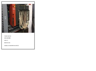
- 1. NAME: PAVAN.D SRN: R22EM807 SEM: 4TH BRANCH: EEE SUBJECT: FUNDAMENTALS OF PLC
- 2. FUNDAMENTALS OF PLC WHAT IS PLC PLC stands for “Programmable Logic Controller”. PLC can be defined as digital electronic device that uses a programmable memory to store instructions and to implement specific functions such as logic, sequencing, counting, timing and arithmetic operations to control machine, and processes. ARCHITECTURE OF PLC The basic architecture of a Programmable Logic Controller (PLC) system consists of several key components that work together to perform control and automation tasks.
- 3. 1. CPU (CENTRAL PROCESSING UNIT) The CPU is the brain of the PLC system. It processes instructions, performs calculations, and controls the overall operation of the PLC. The CPU executes the control program stored in its memory, which consists of a series of instructions that determine the behaviour and logic of the system. 2. INPUT AND OUTPUT MODULES(I/O) Input modules receive signals from sensors and field devices and convert them into digital data that the CPU can process. Output modules receive digital data from the CPU and generate output signals to control actuators, motors, and other devices. I/0 modules are connected to the PLC's backplane or rack, which provides power supply and communication channels for data exchange. 3. MEMORY PLCs have different types of memory to store the control program, data, and system parameters. Program memory stores the control program written by the programmer, which determines the behaviour and logic of the PLC system Data memory holds variables and data used by the program during runtime. System memory stores system parameters and configuration settings 4. POWER SUPPLY UNIT (PSU) The PSU supplies power to the PLC system, ensuring proper operation of all components. It converts the incoming power supply (AC or DC to the voltage levels required by the PLC system. 5. COMMUNICATION INTERFACE PLC systems often have communication interfaces to interact with external devices, networks, or supervisory systems These interfaces enable data exchange, remote monitoring, and control of the PLC system.
- 4. CLASSIFICATION OF PLC INPUT AND OUTPUT MODULES 1. Digital I/O Module The digital module is also called Discrete Module. In this module, the I/O signal work on the binary system i.e. only 0 or 1 value. For the digital input module, only the 1-bit signal is used. It is useful in the ON or OFF condition. Based on Input and Output, the digital module is of two types. Digital Input Module Digital Output Module The digital I/O signal gives status in the different form like – 1. High/Low, True/False and 1/0 for General Status 2. ON/OFF for Load Condition 3. Activated/Deactivated for Switching Mechanism 4. Close/ Open for the Switching Contact Status
- 5. Examples: Push switch, Toggle switch, Rocker switch, Selector switch, Proximity switch, Limit switch and e tc are the example of the Digital Input Signal. Examples: Lamp, Coil, Buzzer, Relay, Motor, Fan, Heater, Actuator, Solenoid Valve and etc are the example of the Digital Output Signal. 2. Analog I/O Module The analog module is called a Continous Module. Usually, the voltage or current is given to the input module in the form of an analog signal. For the analog input module, 12-bit or 13-bit signal is used. Generally, analog input signals operate in the range of 4-20 mA, 0-20 mA, 1-5 V, etc. Again, analog I/O modules are also of two types. Analog Input Module Analog Output Module Examples: Temperature detection switch, Pressure detection switch, Flow detection switch, Level detection switch, Limit detection switch, Position detection switch, PH Level detection switch are the best example of the Analog Input Signal. Examples: Temperature Transmitter, Thermocouples, Pressure Transmitter, Flow Transmitter, Level Transmitter, etc., are the example of the Analog Output Signal. In the PLC system, we can use either digital or analog types of modules as per the project requirements.
- 6. Representation of Input-Output Module In PLC Programming In the PLC programming, Input modules are represented by the ‘I‘ Output modules are presented by the ‘Q‘ For the Ladder Diagram (LD) programming language, normally open and normally closed contact is used in the form of input. And the coil or lamp is used in the form of output. The symbolic representation of I and O modules in the LD program. RULES OF PLC LADDER DIAGRAM: Inputs can be used in Series as well as Parallel to form a connection Outputs (or coil) can be used only in Parallel One Input can be used in multiple times in one program One Output cannot be used multiple times in one program, except in Set/Reset and Latch/ Unlatch functions Input Address cannot be used as an Output Address Outputs Address can be used as Inputs Address
- 7. NEED OF PLC: To get the automation in the process Controlling of equipment’s with just one click. Arranging so many controllers as per our requirements To make the efficient use of digital electronics and control system Real time application of microcontrollers, microprocessor and input-output modules. ADVANTAGES OF PLC: The highlighting advantage of PLC is to increase the reliability and flexibility in industrial automation. It is simple to operate and understand It requires very less operation time to perform any task. It gives a fast response to the connected system. It provides high accuracy as compared to the relay network. It needs low maintenance. It has remote control capability. It gives supervisory control capability. It can operate in extreme environments. PLC programs are easy to write and understand. There are many programming languages used in PLC. Out of them, the ladder diagram is very popular and user- friendly. DISADVANTAGES OF PLC: You can operate one program at a time in a compact PLC. In the case of PLC, we can not use software and parts of one PLC manufacturer in another PLC manufacturer. When power restores, PLC automatically starts. It can damage the system. To avoid the damage, you can program the output to go to the fail-safe mode.
- 8. APPLICATIONS OF PLC: Smart Traffic Control Signal System. Smart Elevator Control System. Fire Detection and Alarm System. Water Tank Level Control System Car Washing and Parking System. Flashing Light Controlling System. Automatic Door Opening/Closing System. Steel Industry Glass Industry Paper industry