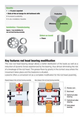
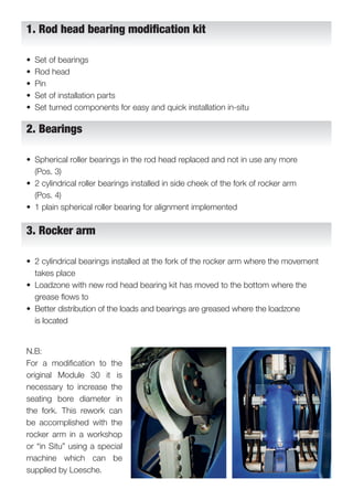
My
My
ROD HEAD ASSEMBLY MODIFICATION
BETTER DISTRIBUTION OF FORCES AT ROCKER ARMS
Key features rod head bearing modification
The new rod head bearing design allows a better distribution of the loads as well as a
reduction of dynamic forces experienced by the bearing, thus almost eliminating the risk
of a breakage of the rod head. The grease flows by gravity in the contact area where the
movement takes place and the loadzone is situated.
Loesche offers a conversion kit as a complete modification for the rod head assembly.
Production
Efficiency Availability
Benefits
• > 10 years expected
• State-of-the-art design for old-fashioned mills
• Increased availability
• In-situ installation feasible
Installation / Commissioning
Approx. 1 day installation for
one rod head bearing assembly
Return on invest
< 1Years
1
1110
2
12
3
13
4
14
5
15
6
16
7
17
8
18
9
19
20 21 22 23 24 25 26 27 28
1
1110
2
12
3
13
4
14
5
15
6
16
7
17
8
18
9
19
20 21 22 23 24 25 26 27 28
1
1110
2
12
3
13
4
14
5
15
6
16
7
17
8
18
9
19
20 21 22 23 24 25 26 27 28
1
1110
2
12
3
13
4
14
5
15
6
16
7
17
8
18
9
19
20 21 22 23 24 25 26 27 28
1
1110
2
12
3
13
4
14
5
15
6
16
7
17
8
18
9
19
20 21 22 23 24 25 26 27 28
1
1110
2
12
3
13
4
14
5
15
6
16
7
17
8
18
9
19
20 21 22 23 24 25 26 27 28
1
1110
2
12
3
13
4
14
5
15
6
16
7
17
8
18
9
19
20 21 22 23 24 25 26 27 28
1
1110
2
12
3
13
4
14
5
15
6
16
7
17
8
18
9
19
20 21 22 23 24 25 26 27 28
Loadzone
1
1110
2
12
3
13
4
14
5
15
6
16
7
17
8
20 21 22 23 24 25 26 27
Rocker arm
1
1110
2
12
3
13
4
14
5
15
6
16
7
17
8
18
9
20 21 22 23 24 25 26 27 28
Rod head
1
1110
2
12
3
13
4
14
5
15
6
16
7
17
8
18
9
19
20 21 22 23 24 25 26 27 28
Spherical roller
bearing
1
1110
2
12
3
13
4
14
5
15
6
16
7
17
8
18
9
19
20 21 22 23 24 25 26 27 28
Cylindrical roller
bearing
1
1110
2
12
3
13
4
14
5
15
6
16
7
17
8
18
9
19
20 21 22 23 24 25 26 27 28
Articulated
bearing
Original design of the rod head bearing assembly New design of the rod head bearing assembly
Loadzone
• Set of bearings
• Rod head
• Pin
• Set of installation parts
• Set turned components for easy and quick installation in-situ
• Spherical roller bearings in the rod head replaced and not in use any more
(Pos. 3)
• 2 cylindrical roller bearings installed in side cheek of the fork of rocker arm
(Pos. 4)
• 1 plain spherical roller bearing for alignment implemented
• 2 cylindrical bearings installed at the fork of the rocker arm where the movement
takes place
• Loadzone with new rod head bearing kit has moved to the bottom where the
grease flows to
• Better distribution of the loads and bearings are greased where the loadzone
is located
N.B:
For a modification to the
original Module 30 it is
necessary to increase the
seating bore diameter in
the fork. This rework can
be accomplished with the
rocker arm in a workshop
or “in Situ” using a special
machine which can be
supplied by Loesche.
1. Rod head bearing modification kit
2. Bearings
3. Rocker arm
For further information such as detailed
scope of supply and quotations the
Customer Service Sales department can
be contacted under:
LOESCHE GmbH
– Customer Service Sales –
Hansaallee 243
D-40549 Düsseldorf, Germany
Phone 	 +49 - 211 - 5353 - 0
Fax 	 +49 - 211 - 5353 - 500
Email 	 customerservice@loesche.de
www.loesche.com

Rod Head Assembly Modification | Customer Service Sales

  • 1.
    My My ROD HEAD ASSEMBLYMODIFICATION BETTER DISTRIBUTION OF FORCES AT ROCKER ARMS
  • 2.
    Key features rodhead bearing modification The new rod head bearing design allows a better distribution of the loads as well as a reduction of dynamic forces experienced by the bearing, thus almost eliminating the risk of a breakage of the rod head. The grease flows by gravity in the contact area where the movement takes place and the loadzone is situated. Loesche offers a conversion kit as a complete modification for the rod head assembly. Production Efficiency Availability Benefits • > 10 years expected • State-of-the-art design for old-fashioned mills • Increased availability • In-situ installation feasible Installation / Commissioning Approx. 1 day installation for one rod head bearing assembly Return on invest < 1Years 1 1110 2 12 3 13 4 14 5 15 6 16 7 17 8 18 9 19 20 21 22 23 24 25 26 27 28 1 1110 2 12 3 13 4 14 5 15 6 16 7 17 8 18 9 19 20 21 22 23 24 25 26 27 28 1 1110 2 12 3 13 4 14 5 15 6 16 7 17 8 18 9 19 20 21 22 23 24 25 26 27 28 1 1110 2 12 3 13 4 14 5 15 6 16 7 17 8 18 9 19 20 21 22 23 24 25 26 27 28 1 1110 2 12 3 13 4 14 5 15 6 16 7 17 8 18 9 19 20 21 22 23 24 25 26 27 28 1 1110 2 12 3 13 4 14 5 15 6 16 7 17 8 18 9 19 20 21 22 23 24 25 26 27 28 1 1110 2 12 3 13 4 14 5 15 6 16 7 17 8 18 9 19 20 21 22 23 24 25 26 27 28 1 1110 2 12 3 13 4 14 5 15 6 16 7 17 8 18 9 19 20 21 22 23 24 25 26 27 28 Loadzone 1 1110 2 12 3 13 4 14 5 15 6 16 7 17 8 20 21 22 23 24 25 26 27 Rocker arm 1 1110 2 12 3 13 4 14 5 15 6 16 7 17 8 18 9 20 21 22 23 24 25 26 27 28 Rod head 1 1110 2 12 3 13 4 14 5 15 6 16 7 17 8 18 9 19 20 21 22 23 24 25 26 27 28 Spherical roller bearing 1 1110 2 12 3 13 4 14 5 15 6 16 7 17 8 18 9 19 20 21 22 23 24 25 26 27 28 Cylindrical roller bearing 1 1110 2 12 3 13 4 14 5 15 6 16 7 17 8 18 9 19 20 21 22 23 24 25 26 27 28 Articulated bearing Original design of the rod head bearing assembly New design of the rod head bearing assembly Loadzone
  • 3.
    • Set ofbearings • Rod head • Pin • Set of installation parts • Set turned components for easy and quick installation in-situ • Spherical roller bearings in the rod head replaced and not in use any more (Pos. 3) • 2 cylindrical roller bearings installed in side cheek of the fork of rocker arm (Pos. 4) • 1 plain spherical roller bearing for alignment implemented • 2 cylindrical bearings installed at the fork of the rocker arm where the movement takes place • Loadzone with new rod head bearing kit has moved to the bottom where the grease flows to • Better distribution of the loads and bearings are greased where the loadzone is located N.B: For a modification to the original Module 30 it is necessary to increase the seating bore diameter in the fork. This rework can be accomplished with the rocker arm in a workshop or “in Situ” using a special machine which can be supplied by Loesche. 1. Rod head bearing modification kit 2. Bearings 3. Rocker arm
  • 4.
    For further informationsuch as detailed scope of supply and quotations the Customer Service Sales department can be contacted under: LOESCHE GmbH – Customer Service Sales – Hansaallee 243 D-40549 Düsseldorf, Germany Phone +49 - 211 - 5353 - 0 Fax +49 - 211 - 5353 - 500 Email customerservice@loesche.de www.loesche.com