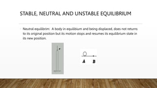
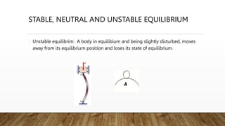
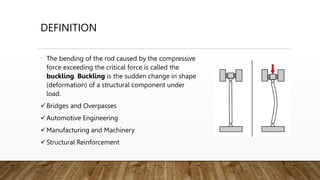
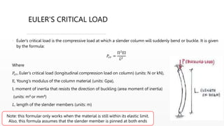
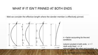
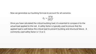
ROD BUCKLING
DEFINITION AND FUNDAMENTALS OF CALCULATION
STABLE, NEUTRAL AND UNSTABLE EQUILIBRIUM
• Stable equilibrim: A body in static equilibium and being displaced slightly,
returns to its original position and continues to remain in equilibrium.
STABLE, NEUTRAL AND UNSTABLE EQUILIBRIUM
• Neutral equilibrim: A body in equilibium and being displaced, does not returns
to its original position but its motion stops and resumes its equilibrium state in
its new position.
STABLE, NEUTRAL AND UNSTABLE EQUILIBRIUM
• Unstable equilibrim: A body in equilibium and being slightly disturbed, moves
away from its equilibrium position and loses its state of equilibrium.
DEFINITION
• The bending of the rod caused by the compressive
force exceeding the critical force is called the
buckling. Buckling is the sudden change in shape
(deformation) of a structural component under
load.
Bridges and Overpasses
Automotive Engineering
Manufacturing and Machinery
Structural Reinforcement
EXAMPLES OF REAL TIME ROD BUCKLING
Therefore to design these slender members for safety we need to understand how to calculate
the critical buckling load, which is what the Euler’s buckling formular is about
EULER'S CRITICAL LOAD
• Euler's critical load is the compressive load at which a slender column will suddenly bend or buckle. It is given
by the formula:
𝑃𝑐𝑟 =
Π2
ΕΙ
𝐿2
Where
𝑃𝑐𝑟, Euler's critical load (longitudinal compression load on column) (units: N or kN),
Ε, Young's modulus of the column material (units: Gpa),
Ι, moment of inertia that resists the direction of buckling (area moment of inertia)
(units: m4 or mm4)
𝐿, length of the slender members (units: m)
Note: this formular only works when the material is still within its elastic limit.
Also, this formula assumes that the slender member is pinned at both ends
WHAT IF IT ISN’T PINNED AT BOTH ENDS
• Well we consider the effective length where the slender member is effectively pinned.
n = factor accounting for the end
conditions
•column pivoted in both ends : n = 1
•both ends fixed : n = 4
•one end fixed; the other end rounded : n
= 2
•one end fixed; one end free : n = 0.25
• Where
• K = (1 / n)1/2 factor accounting for the end conditions
n 1 4 2 0.25
K 1 0.5 0.7 2
K in the table above is the effective
length factor.
• Now we generalise our buckling formula to account for all scenarios
𝑃𝑐𝑟 =
Π2
ΕΙ
(𝐾𝐿)2
• Once you have calculated the critical buckling load, it's essential to compare it to the
actual load applied to the rod. A safety factor is typically used to ensure that the
applied load is well below the critical load to prevent buckling and structural failure. A
commonly used safety factor is 1.5 or 2.
CRITICAL BUCKLING STRESS
𝜎𝑐𝑟 =
𝑃𝑐𝑟
𝐴
• Where
• A = cross-sectional area
• Therefore:
𝜎𝑐𝑟 =
Π2
ΕΙ
(
𝐾𝐿
𝑟
)2
• Where
• r is the radius of gyration (𝑟 =
𝐼
𝐴
) (units: m or mm)
•
𝐿
𝑟
is the slenderness ratio: the higher it is, the more”slender” the member is.
• higher slenderness ratio -
lower critical stress to
cause buckling
• lower slenderness ratio -
higher critical stress to
cause buckling

ROD BUCKLING.pptx

  • 1.
    ROD BUCKLING DEFINITION ANDFUNDAMENTALS OF CALCULATION
  • 2.
    STABLE, NEUTRAL ANDUNSTABLE EQUILIBRIUM • Stable equilibrim: A body in static equilibium and being displaced slightly, returns to its original position and continues to remain in equilibrium.
  • 3.
    STABLE, NEUTRAL ANDUNSTABLE EQUILIBRIUM • Neutral equilibrim: A body in equilibium and being displaced, does not returns to its original position but its motion stops and resumes its equilibrium state in its new position.
  • 4.
    STABLE, NEUTRAL ANDUNSTABLE EQUILIBRIUM • Unstable equilibrim: A body in equilibium and being slightly disturbed, moves away from its equilibrium position and loses its state of equilibrium.
  • 5.
    DEFINITION • The bendingof the rod caused by the compressive force exceeding the critical force is called the buckling. Buckling is the sudden change in shape (deformation) of a structural component under load. Bridges and Overpasses Automotive Engineering Manufacturing and Machinery Structural Reinforcement
  • 6.
    EXAMPLES OF REALTIME ROD BUCKLING Therefore to design these slender members for safety we need to understand how to calculate the critical buckling load, which is what the Euler’s buckling formular is about
  • 7.
    EULER'S CRITICAL LOAD •Euler's critical load is the compressive load at which a slender column will suddenly bend or buckle. It is given by the formula: 𝑃𝑐𝑟 = Π2 ΕΙ 𝐿2 Where 𝑃𝑐𝑟, Euler's critical load (longitudinal compression load on column) (units: N or kN), Ε, Young's modulus of the column material (units: Gpa), Ι, moment of inertia that resists the direction of buckling (area moment of inertia) (units: m4 or mm4) 𝐿, length of the slender members (units: m) Note: this formular only works when the material is still within its elastic limit. Also, this formula assumes that the slender member is pinned at both ends
  • 8.
    WHAT IF ITISN’T PINNED AT BOTH ENDS • Well we consider the effective length where the slender member is effectively pinned. n = factor accounting for the end conditions •column pivoted in both ends : n = 1 •both ends fixed : n = 4 •one end fixed; the other end rounded : n = 2 •one end fixed; one end free : n = 0.25
  • 9.
    • Where • K= (1 / n)1/2 factor accounting for the end conditions n 1 4 2 0.25 K 1 0.5 0.7 2 K in the table above is the effective length factor.
  • 10.
    • Now wegeneralise our buckling formula to account for all scenarios 𝑃𝑐𝑟 = Π2 ΕΙ (𝐾𝐿)2 • Once you have calculated the critical buckling load, it's essential to compare it to the actual load applied to the rod. A safety factor is typically used to ensure that the applied load is well below the critical load to prevent buckling and structural failure. A commonly used safety factor is 1.5 or 2.
  • 11.
    CRITICAL BUCKLING STRESS 𝜎𝑐𝑟= 𝑃𝑐𝑟 𝐴 • Where • A = cross-sectional area • Therefore: 𝜎𝑐𝑟 = Π2 ΕΙ ( 𝐾𝐿 𝑟 )2 • Where • r is the radius of gyration (𝑟 = 𝐼 𝐴 ) (units: m or mm) • 𝐿 𝑟 is the slenderness ratio: the higher it is, the more”slender” the member is. • higher slenderness ratio - lower critical stress to cause buckling • lower slenderness ratio - higher critical stress to cause buckling

Editor's Notes

  • #6 Bridges and Overpasses: In bridge design, the stability of support columns and piers is essential. Buckling can occur in the vertical supports of a bridge if they are not designed to withstand the compressive loads from the weight of the bridge and traffic. Automotive Engineering: Automotive engineers consider rod buckling when designing vehicle structures, especially in components like the chassis and suspension system. Ensuring these components do not buckle under various loads is crucial for vehicle safety. Manufacturing and Machinery: In manufacturing and industrial machinery, slender rods and shafts are commonly used for transmitting power and motion. Ensuring these components do not buckle under torque and axial loads is vital for machinery reliability and safety. Structural Reinforcement: Engineers use buckling calculations to determine the need for and placement of structural reinforcements, such as braces and trusses, in buildings and other structures. These reinforcements prevent rods and columns from buckling and enhance overall stability.
  • #10 n = factor accounting for the end conditions
  • #11 n = factor accounting for the end conditions