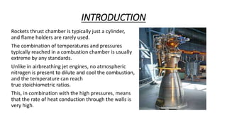
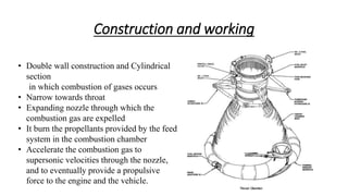
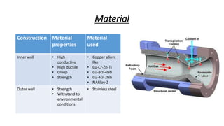
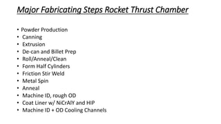
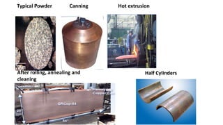
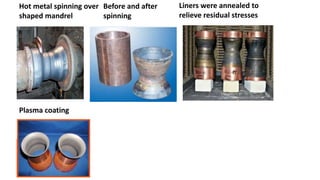
Rocket Thrust Chamber Body
Amrita School of Engineering Coimbatore
Submitted by:
1.ARUNABHA BHATTA (CB.EN.P2.EDN17008)
2.GOURI SAGAR GHONGADE(CB.EN.P2.EDN17013)
3.PRATHAMESH DADASAHEB PATIL(CB.EN.P2EDN17020)
INTRODUCTION
Rockets thrust chamber is typically just a cylinder,
and flame holders are rarely used.
The combination of temperatures and pressures
typically reached in a combustion chamber is usually
extreme by any standards.
Unlike in airbreathing jet engines, no atmospheric
nitrogen is present to dilute and cool the combustion,
and the temperature can reach
true stoichiometric ratios.
This, in combination with the high pressures, means
that the rate of heat conduction through the walls is
very high.
Construction and working
• Double wall construction and Cylindrical
section
in which combustion of gases occurs
• Narrow towards throat
• Expanding nozzle through which the
combustion gas are expelled
• It burn the propellants provided by the feed
system in the combustion chamber
• Accelerate the combustion gas to
supersonic velocities through the nozzle,
and to eventually provide a propulsive
force to the engine and the vehicle.
Material properties
• High Thermal conductivity
• Creep
• High ductile
• Withstand to maximum temperature
• Mechanical strength
• More Life
Material
Construction Material
properties
Material
used
Inner wall • High
conductive
• High ductile
• Creep
• Strength
• Copper alloys
like
• Cu-Cr-Zn-Ti
• Cu-8cr-4Nb
• Cu-4cr-2Nb
• NARloy-Z
Outer wall • Strength
• Withstand to
environmental
conditions
• Stainless steel
Major Fabricating Steps Rocket Thrust Chamber
• Powder Production
• Canning
• Extrusion
• De-can and Billet Prep
• Roll/Anneal/Clean
• Form Half Cylinders
• Friction Stir Weld
• Metal Spin
• Anneal
• Machine ID, rough OD
• Coat Liner w/ NiCrAlY and HIP
• Machine ID + OD Cooling Channels
Typical Powder Canning Hot extrusion
After rolling, annealing and
cleaning
Half Cylinders
Hot metal spinning over
shaped mandrel
Before and after
spinning
Liners were annealed to
relieve residual stresses
Plasma coating
Application
• rocket combustion chamber to reduce oscillations
• aircraft
• space craft
Future Scope
• reduce weight of combustion chamber
• various design combustion chamber
• various design combustion chamber nozzle
Conclusions
• It has a good combination of mechanical properties
making it well suited for rocket thrust chambers
• It can be readily formed, joined and machined using conventional
techniques for copper-based alloys.
• It fabrication processes can be easily scaled to
produce large components
• It can be fabricated into other high temperature, high
heat flux components besides rocket engine liners
References
• Fabrication of GRCop-84 Rocket Thrust Chambers
1.William S. Loewenthal and 2.David L. Ellis
1. Ohio Aerospace Institute, NASA Glenn Research Center, MS 49-1, Cleveland OH 441335
2. NASA Glenn Research Center, MS 49-1, Cleveland OH 441335
• http://www.spacex.com/news/2014/07/31/spacex-launches-3d-printed-part-space-creates-
printed-engine-chamber-crewed
• https://en.wikipedia.org/wiki/Rocket_engine#Combustion_chamber

Rocket thrust chamber

  • 1.
    Rocket Thrust ChamberBody Amrita School of Engineering Coimbatore Submitted by: 1.ARUNABHA BHATTA (CB.EN.P2.EDN17008) 2.GOURI SAGAR GHONGADE(CB.EN.P2.EDN17013) 3.PRATHAMESH DADASAHEB PATIL(CB.EN.P2EDN17020)
  • 2.
    INTRODUCTION Rockets thrust chamberis typically just a cylinder, and flame holders are rarely used. The combination of temperatures and pressures typically reached in a combustion chamber is usually extreme by any standards. Unlike in airbreathing jet engines, no atmospheric nitrogen is present to dilute and cool the combustion, and the temperature can reach true stoichiometric ratios. This, in combination with the high pressures, means that the rate of heat conduction through the walls is very high.
  • 3.
    Construction and working •Double wall construction and Cylindrical section in which combustion of gases occurs • Narrow towards throat • Expanding nozzle through which the combustion gas are expelled • It burn the propellants provided by the feed system in the combustion chamber • Accelerate the combustion gas to supersonic velocities through the nozzle, and to eventually provide a propulsive force to the engine and the vehicle.
  • 4.
    Material properties • HighThermal conductivity • Creep • High ductile • Withstand to maximum temperature • Mechanical strength • More Life
  • 5.
    Material Construction Material properties Material used Inner wall• High conductive • High ductile • Creep • Strength • Copper alloys like • Cu-Cr-Zn-Ti • Cu-8cr-4Nb • Cu-4cr-2Nb • NARloy-Z Outer wall • Strength • Withstand to environmental conditions • Stainless steel
  • 6.
    Major Fabricating StepsRocket Thrust Chamber • Powder Production • Canning • Extrusion • De-can and Billet Prep • Roll/Anneal/Clean • Form Half Cylinders • Friction Stir Weld • Metal Spin • Anneal • Machine ID, rough OD • Coat Liner w/ NiCrAlY and HIP • Machine ID + OD Cooling Channels
  • 7.
    Typical Powder CanningHot extrusion After rolling, annealing and cleaning Half Cylinders
  • 8.
    Hot metal spinningover shaped mandrel Before and after spinning Liners were annealed to relieve residual stresses Plasma coating
  • 9.
    Application • rocket combustionchamber to reduce oscillations • aircraft • space craft
  • 10.
    Future Scope • reduceweight of combustion chamber • various design combustion chamber • various design combustion chamber nozzle
  • 11.
    Conclusions • It hasa good combination of mechanical properties making it well suited for rocket thrust chambers • It can be readily formed, joined and machined using conventional techniques for copper-based alloys. • It fabrication processes can be easily scaled to produce large components • It can be fabricated into other high temperature, high heat flux components besides rocket engine liners
  • 12.
    References • Fabrication ofGRCop-84 Rocket Thrust Chambers 1.William S. Loewenthal and 2.David L. Ellis 1. Ohio Aerospace Institute, NASA Glenn Research Center, MS 49-1, Cleveland OH 441335 2. NASA Glenn Research Center, MS 49-1, Cleveland OH 441335 • http://www.spacex.com/news/2014/07/31/spacex-launches-3d-printed-part-space-creates- printed-engine-chamber-crewed • https://en.wikipedia.org/wiki/Rocket_engine#Combustion_chamber