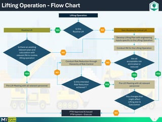
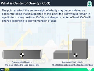
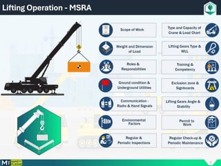
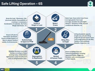
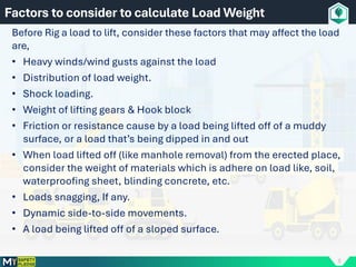
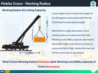
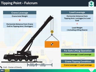
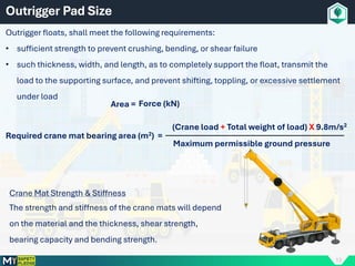
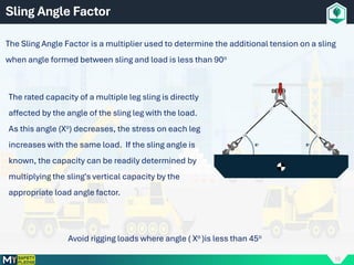
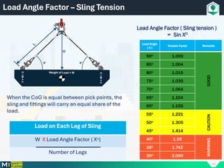
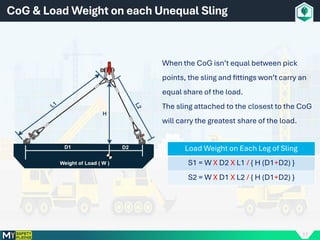
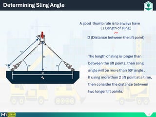
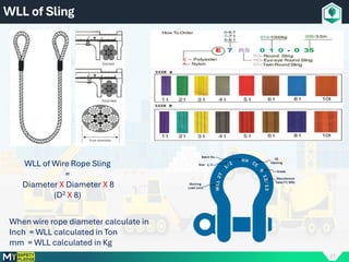
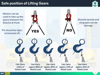
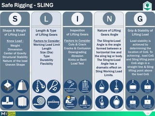
1
LIFTING OPERATION
& RIGGING
SAFETY
2
Ensuring safety in lifting operations is not just a good practice; it’s a necessity.
A safe operation ensures:
Protection of Human Lives : The primary concern is always human safety. Proper
lifting operations safety minimizes the chances of fatal
accidents.
Reduction in Financial Losses : Accidents can lead to equipment damage, legal
liabilities, and compensation, which can be financially
draining.
Efficiency and Productivity : A well-executed, safe operation avoids delays,
equipment downtimes, and unnecessary costs.
Why is Safe Lifting Operation Important?
3
Hazards during Lifting Operation
4
Lifting Operation - Flow Chart
Lifting Operation
Is this
Routine Lift
Non-Routine & Critical Lift
Develop Lifting Plan with engineering
inputs specific to the Lifting Operation
PTW Approved & Issued
PTW system – Execute
Conduct RA for the Lifting Operation
Are all
acceptable risk
eliminated or
reduced
Pre-Lift Meeting with all relevant
personnel
Any changes that
might affect
Lifting plan &
Calculation
Routine Lift
Is there an existing
relevant plan and
calculation with
relevant RA to routine
lifting operation
Pre-Lift Meeting with all relevant personnel
Conduct Risk Reduction through
Hierarchy of Risk Control
Is this intended
Risk Reduction
achieved ?
YES
NO
NO
NO
NO
NO
YES
YES
YES YES
5
What is Center of Gravity ( CoG)
The point at which the entire weight of a body may be considered as
concentrated so that if supported at this point the body would remain in
equilibrium in any position. CoG is not always in center of load. CoG will
change according to body dimension of load
Symmetrical Load –
The CoG alone the load center line
Asymmetrical Load -
The CoG is not alone the load center line
6
Lifting Operation - MSRA
7
Safe Lifting Operation – 6S
8
Before Rig a load to lift, consider these factors that may affect the load
are,
• Heavy winds/wind gusts against the load
• Distribution of load weight.
• Shock loading.
• Weight of lifting gears & Hook block
• Friction or resistance cause by a load being lifted off of a muddy
surface, or a load that’s being dipped in and out
• When load lifted off (like manhole removal) from the erected place,
consider the weight of materials which is adhere on load like, soil,
waterproofing sheet, blinding concrete, etc.
• Loads snagging, If any.
• Dynamic side-to-side movements.
• A load being lifted off of a sloped surface.
Factors to consider to calculate Load Weight
9
Mobile Crane - Working Radius
Working Radius V/s Lifting Capacity
When Crane Working Radius Increases Safe Working Load (SWL) capacity of
Crane Decreases.
Load weight must include the weight of
all lifting gears associated with the lift,
including the hook block weight
When Boom angle decreases crane
working radius increase and the Safe
Working Load (SWL) capacity decreases.
Above 800 angle load will be so close to
crane and risk is high, where the load will
hit the crane due to any reason
10
Tipping Point - Fulcrum
Crane Leverage
Crane total Weight
X
Horizontal distance from Crane
CoG to Tipping Axis ( Outrigger)
Load Leverage
Horizontal distance from
Tipping Axis ( outrigger) to Load
CoG
X
Load Weight
( including Lifting Gears)
For Safe Lifting Operation
Crane Leverage > Load Leverage
Crane Tipping Condition
Crane Leverage <= Load Leverage
CoG - Center of Gravity
11
Weight of Lifting Load while Descent
When crane hook block Descent below
the level of crane outrigger total weight
of the lifting load will be more than the
actual weight of load. Due to, while hook
block moving down below the outrigger
the lengths of each falls increases.
Weight of Falls
Weight of Each falls per Meter ( Y)
X
Number of Falls
Total Weight of Lifting Load
Total Weight of Falls
+
Crane Hook Block
+
Lifting Gears
+
Weight of Load
12
Truck Mounted Crane – 360O Working Zone
Lifting over the crane’s Front side (driver cabin) risk factor
is higher due to the increase of working radius
Front Side
Left Side
Right Side
Rear Side
And also due to the risk of the load moving
over the cabin which can cause serious
accident or property damage
Distance from the CoG of the crane to its front bumper
+
Safe distance for load from crane body
13
Outrigger Pad Size
Outrigger floats, shall meet the following requirements:
• sufficient strength to prevent crushing, bending, or shear failure
• such thickness, width, and length, as to completely support the float, transmit the
load to the supporting surface, and prevent shifting, toppling, or excessive settlement
under load
Maximum permissible ground pressure
Required crane mat bearing area (m2) =
(Crane load + Total weight of load) X 9.8m/s2
Area = Force (kN)
Crane Mat Strength & Stiffness
The strength and stiffness of the crane mats will depend
on the material and the thickness, shear strength,
bearing capacity and bending strength.
14
Sling Safety
15
Sling Angle Factor
The Sling Angle Factor is a multiplier used to determine the additional tension on a sling
when angle formed between sling and load is less than 90o
Avoid rigging loads where angle ( Xo )is less than 45o
The rated capacity of a multiple leg sling is directly
affected by the angle of the sling leg with the load.
As this angle (Xo) decreases, the stress on each leg
increases with the same load. If the sling angle is
known, the capacity can be readily determined by
multiplying the sling's vertical capacity by the
appropriate load angle factor.
16
Load Angle Factor – Sling Tension
Load Angle Factor ( Sling tension )
= Sin XO
Load on Each Leg of Sling
W X Load Angle Factor ( XO)
Number of Legs
Load Angle
( X )
Tension Factor Remarks
90o 1.000
GOOD
85o 1.004
80o 1.015
75o 1.035
70o 1.064
65o 1.104
60o 1.155
55o 1.221
CAUTION
50o 1.305
45o 1.414
40o 1.55
WARNING
35o 1.742
30o 2.000
When the CoG is equal between pick points, the
sling and fittings will carry an equal share of the
load.
17
CoG & Load Weight on each Unequal Sling
When the CoG isn’t equal between pick
points, the sling and fittings won’t carry an
equal share of the load.
The sling attached to the closest to the CoG
will carry the greatest share of the load.
Load Weight on Each Leg of Sling
S1 = W X D2 X L1 / { H (D1+D2) }
S2 = W X D1 X L2 / { H (D1+D2) }
18
Determining Sling Angle
A good thumb rule is to always have
L ( Length of sling )
>=
D (Distance between the lift point)
The length of sling is longer than
between the lift points, then sling
angle will be more than 60o angle .
If using more than 2 lift point at a time,
then consider the distance between
two longer lift points.
19
Sling Angle V/S Sling Load Capacity
Sling Angle
Sling Load Capacity %
20
Sling Angle – Choker Hitch
Sling Angle Loss Factor.
The use of choker hitches reduce a sling’s load limit.
The angle of choke can reduce the load limit further.
Once angle of choke has been determined multiply
the appropriate loss factor to slings capacity to
determine the reduced load limit.
The total load weight must not exceed the reduced
load limit.
Choker Hitch Rated Capacity - A choker hitch will
have 75% of the capacity of a single leg vertical hitch
only if the corners are softened and the horizontal
angle is greater than 30°.
Angle of Choke
(Degree )
Loss Factor Remarks
> 120 1.000
GOOD
120 - 90 0.870
89 - 60 0.740
CAUTION
59 – 30 0.620
29 – 0 0.490 DANGER
21
WLL of Sling
WLL of Wire Rope Sling
=
Diameter X Diameter X 8
(D2 X 8)
When wire rope diameter calculate in
Inch = WLL calculated in Ton
mm = WLL calculated in Kg
22
Safe position of Lifting Gears
Washer can be
used to take up the
space between the
Shackle & Hook
Pin should be tight,
not backed off.
Shackle spread and
sling eyes can be
damage
23
Wire Clip Safe position
24
Safe Rigging - SLING
25
Mobile Crane - Hand Signals
26
What Size of Crane required for Safe Lifting
Crane Chart ( Load X Working Radius )
27
Mobile Crane Lift Calculation Sheet
28
Thank You

Rigging and slinging safety training for all workers

  • 1.
  • 2.
    2 Ensuring safety inlifting operations is not just a good practice; it’s a necessity. A safe operation ensures: Protection of Human Lives : The primary concern is always human safety. Proper lifting operations safety minimizes the chances of fatal accidents. Reduction in Financial Losses : Accidents can lead to equipment damage, legal liabilities, and compensation, which can be financially draining. Efficiency and Productivity : A well-executed, safe operation avoids delays, equipment downtimes, and unnecessary costs. Why is Safe Lifting Operation Important?
  • 3.
  • 4.
    4 Lifting Operation -Flow Chart Lifting Operation Is this Routine Lift Non-Routine & Critical Lift Develop Lifting Plan with engineering inputs specific to the Lifting Operation PTW Approved & Issued PTW system – Execute Conduct RA for the Lifting Operation Are all acceptable risk eliminated or reduced Pre-Lift Meeting with all relevant personnel Any changes that might affect Lifting plan & Calculation Routine Lift Is there an existing relevant plan and calculation with relevant RA to routine lifting operation Pre-Lift Meeting with all relevant personnel Conduct Risk Reduction through Hierarchy of Risk Control Is this intended Risk Reduction achieved ? YES NO NO NO NO NO YES YES YES YES
  • 5.
    5 What is Centerof Gravity ( CoG) The point at which the entire weight of a body may be considered as concentrated so that if supported at this point the body would remain in equilibrium in any position. CoG is not always in center of load. CoG will change according to body dimension of load Symmetrical Load – The CoG alone the load center line Asymmetrical Load - The CoG is not alone the load center line
  • 6.
  • 7.
  • 8.
    8 Before Rig aload to lift, consider these factors that may affect the load are, • Heavy winds/wind gusts against the load • Distribution of load weight. • Shock loading. • Weight of lifting gears & Hook block • Friction or resistance cause by a load being lifted off of a muddy surface, or a load that’s being dipped in and out • When load lifted off (like manhole removal) from the erected place, consider the weight of materials which is adhere on load like, soil, waterproofing sheet, blinding concrete, etc. • Loads snagging, If any. • Dynamic side-to-side movements. • A load being lifted off of a sloped surface. Factors to consider to calculate Load Weight
  • 9.
    9 Mobile Crane -Working Radius Working Radius V/s Lifting Capacity When Crane Working Radius Increases Safe Working Load (SWL) capacity of Crane Decreases. Load weight must include the weight of all lifting gears associated with the lift, including the hook block weight When Boom angle decreases crane working radius increase and the Safe Working Load (SWL) capacity decreases. Above 800 angle load will be so close to crane and risk is high, where the load will hit the crane due to any reason
  • 10.
    10 Tipping Point -Fulcrum Crane Leverage Crane total Weight X Horizontal distance from Crane CoG to Tipping Axis ( Outrigger) Load Leverage Horizontal distance from Tipping Axis ( outrigger) to Load CoG X Load Weight ( including Lifting Gears) For Safe Lifting Operation Crane Leverage > Load Leverage Crane Tipping Condition Crane Leverage <= Load Leverage CoG - Center of Gravity
  • 11.
    11 Weight of LiftingLoad while Descent When crane hook block Descent below the level of crane outrigger total weight of the lifting load will be more than the actual weight of load. Due to, while hook block moving down below the outrigger the lengths of each falls increases. Weight of Falls Weight of Each falls per Meter ( Y) X Number of Falls Total Weight of Lifting Load Total Weight of Falls + Crane Hook Block + Lifting Gears + Weight of Load
  • 12.
    12 Truck Mounted Crane– 360O Working Zone Lifting over the crane’s Front side (driver cabin) risk factor is higher due to the increase of working radius Front Side Left Side Right Side Rear Side And also due to the risk of the load moving over the cabin which can cause serious accident or property damage Distance from the CoG of the crane to its front bumper + Safe distance for load from crane body
  • 13.
    13 Outrigger Pad Size Outriggerfloats, shall meet the following requirements: • sufficient strength to prevent crushing, bending, or shear failure • such thickness, width, and length, as to completely support the float, transmit the load to the supporting surface, and prevent shifting, toppling, or excessive settlement under load Maximum permissible ground pressure Required crane mat bearing area (m2) = (Crane load + Total weight of load) X 9.8m/s2 Area = Force (kN) Crane Mat Strength & Stiffness The strength and stiffness of the crane mats will depend on the material and the thickness, shear strength, bearing capacity and bending strength.
  • 14.
  • 15.
    15 Sling Angle Factor TheSling Angle Factor is a multiplier used to determine the additional tension on a sling when angle formed between sling and load is less than 90o Avoid rigging loads where angle ( Xo )is less than 45o The rated capacity of a multiple leg sling is directly affected by the angle of the sling leg with the load. As this angle (Xo) decreases, the stress on each leg increases with the same load. If the sling angle is known, the capacity can be readily determined by multiplying the sling's vertical capacity by the appropriate load angle factor.
  • 16.
    16 Load Angle Factor– Sling Tension Load Angle Factor ( Sling tension ) = Sin XO Load on Each Leg of Sling W X Load Angle Factor ( XO) Number of Legs Load Angle ( X ) Tension Factor Remarks 90o 1.000 GOOD 85o 1.004 80o 1.015 75o 1.035 70o 1.064 65o 1.104 60o 1.155 55o 1.221 CAUTION 50o 1.305 45o 1.414 40o 1.55 WARNING 35o 1.742 30o 2.000 When the CoG is equal between pick points, the sling and fittings will carry an equal share of the load.
  • 17.
    17 CoG & LoadWeight on each Unequal Sling When the CoG isn’t equal between pick points, the sling and fittings won’t carry an equal share of the load. The sling attached to the closest to the CoG will carry the greatest share of the load. Load Weight on Each Leg of Sling S1 = W X D2 X L1 / { H (D1+D2) } S2 = W X D1 X L2 / { H (D1+D2) }
  • 18.
    18 Determining Sling Angle Agood thumb rule is to always have L ( Length of sling ) >= D (Distance between the lift point) The length of sling is longer than between the lift points, then sling angle will be more than 60o angle . If using more than 2 lift point at a time, then consider the distance between two longer lift points.
  • 19.
    19 Sling Angle V/SSling Load Capacity Sling Angle Sling Load Capacity %
  • 20.
    20 Sling Angle –Choker Hitch Sling Angle Loss Factor. The use of choker hitches reduce a sling’s load limit. The angle of choke can reduce the load limit further. Once angle of choke has been determined multiply the appropriate loss factor to slings capacity to determine the reduced load limit. The total load weight must not exceed the reduced load limit. Choker Hitch Rated Capacity - A choker hitch will have 75% of the capacity of a single leg vertical hitch only if the corners are softened and the horizontal angle is greater than 30°. Angle of Choke (Degree ) Loss Factor Remarks > 120 1.000 GOOD 120 - 90 0.870 89 - 60 0.740 CAUTION 59 – 30 0.620 29 – 0 0.490 DANGER
  • 21.
    21 WLL of Sling WLLof Wire Rope Sling = Diameter X Diameter X 8 (D2 X 8) When wire rope diameter calculate in Inch = WLL calculated in Ton mm = WLL calculated in Kg
  • 22.
    22 Safe position ofLifting Gears Washer can be used to take up the space between the Shackle & Hook Pin should be tight, not backed off. Shackle spread and sling eyes can be damage
  • 23.
  • 24.
  • 25.
    25 Mobile Crane -Hand Signals
  • 26.
    26 What Size ofCrane required for Safe Lifting Crane Chart ( Load X Working Radius )
  • 27.
    27 Mobile Crane LiftCalculation Sheet
  • 28.