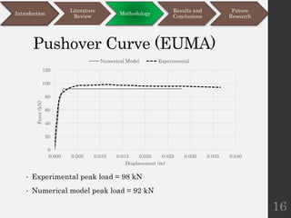
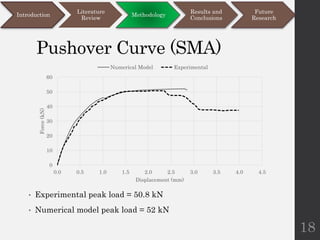
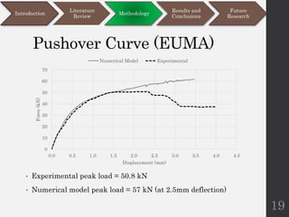
Introduction
• Researches these days are most focused on
Finite element modeling
• Prime objective of finite element modeling is
to achieve results without having to spend
time and money on laboratory experiments
1
Introduction
Literature
Review
Methodology
Results and
Conclusions
Future
Research
Introduction
• Masonry is the most commonly used
construction material in Pakistan and world
over (Rafiq, 2015)
• Seismic forces induce in-plane loads in shear
walls
• Understanding of masonry behavior under in-
plane static and cyclic loading is of prime
importance
2
Introduction
Literature
Review
Methodology
Results and
Conclusions
Future
Research
Literature Review
• There are three major finite element modeling
techniques for masonry (Lourenco and Rots,
1994)
1. Detailed micro-modeling
2. Simplified micro-modeling
3. Macro modeling
3
Introduction
Literature
Review
Methodology
Results and
Conclusions
Future
Research
Simplified micro-modeling
• Two methods have been used in the literature
under simplified micro modeling
1. Springs modeling approach (Campbell,
2012), (Drougkas, 2014).
2. Expanded Units modeling approach
(Abdulla, 2017), (Lourenco, 1996).
4
Introduction
Literature
Review
Methodology
Results and
Conclusions
Future
Research
Springs modeling approach
• This approach considers brick units connected with
mortar through contact elements (interface).
Mortar is defined using non-linear springs.
• Brick & mortar material constitutive relationships
are defined as per pre-defined criteria
• Contact normal and tangential stiffness are
defined by:
𝐾𝑛 =
𝐸𝑚. 𝐴𝑡𝑟𝑖𝑏
𝐿
𝐾𝑠 =
𝐺𝑚. 𝐴𝑡𝑟𝑖𝑏
𝐿
5
Introduction
Literature
Review
Methodology
Results and
Conclusions
Future
Research
Constitutive relationships
Brick Stress-Strain curve (Min.
Eb is taken as 350 times fb)
Mortar Stress-Strain (Min.
Em is taken as 200 times fm)
6
• Mortar shear stress is considered 10% of mortar
strength, ultimate shear strain is considered 25% of
compressive strain
Introduction
Literature
Review
Methodology
Results and
Conclusions
Future
Research
Expanded units modeling
approach
• This approach considers the brick unit as an
‘expanded unit’
• The dimensions of brick are expanded to half
mortar thickness on each side
• The brick properties are adjusted to account
for this approximation
𝐸𝑎𝑑𝑗 =
𝐻𝐸𝑏𝐸𝑚
𝑛ℎ𝑏𝐸𝑚 + (𝑛 − 1)ℎ𝑚𝐸𝑏
7
Introduction
Literature
Review
Methodology
Results and
Conclusions
Future
Research
Material properties
• Drucker Prager’s (DP) non-linear
properties are defined for expanded units.
• DP input requires cohesion (c) and friction
angle (ϕ)
• Contact normal and tangential stiffness
defined by:
𝑘𝑛 =
𝐸𝑏𝐸𝑚
ℎ𝑚 𝐺𝑏 − 𝐺𝑚
; 𝑘𝑠 =
𝐺𝑏𝐺𝑚
ℎ𝑚 𝐺𝑏 − 𝐺𝑚
8
Introduction
Literature
Review
Methodology
Results and
Conclusions
Future
Research
Cohesive zone material
• Cohesive zone material (CZM) law is defined
to model contact delamination with increasing
stresses (ANSYS, 2015).
• Maximum applied stresses and critical
fracture energy values are defined under the
CZM law
9
Introduction
Literature
Review
Methodology
Results and
Conclusions
Future
Research
Problem Statement
• Compilation of various modeling approaches
is desired; different methodologies have not
been tested on similar problems for apple-to-
apple comparison
• Springs modeling approach is computationally
economical but needs improved accuracy
• Expanded units modeling approach provides
more accurate results but computationally
very expensive; efficiency can be improved
• This complex approach also needs
simplification by problem size reduction to
cater for limitations of ‘Student releases’
10
Introduction
Literature
Review
Methodology
Results and
Conclusions
Future
Research
Research Objectives
• To define the numerical model based on the
most efficient approach to reproduce the
mechanical behavior of the masonry walls.
• To evaluate the results of the numerical model
in comparison with the already available
experimental data, and
• To predict the capacity of the tested walls.
11
Introduction
Literature
Review
Methodology
Results and
Conclusions
Future
Research
Methodology
12
• 4 different walls have been modeled in ANSYS
• Springs modeling approach (SMA) and
Expanded units modeling approach (EUMA)
are applied on each of these walls
Introduction
Literature
Review
Methodology
Results and
Conclusions
Future
Research
Wall
Loading
type
Wall dimensions
Vertical
Pressure
Wall A
In-plane
static
1250x2500x175 mm 1.00 MPa
Wall B 990x1000x100 mm 0.30 MPa
Wall C 990x1000x100 mm 1.21 MPa
Wall D
In-plane
pseudo-
dynamic
1200x1200x110 mm 0.70 MPa
Mesh Sensitivity study
• Springs modeling approach is found to be
unaffected by mesh size, therefore, minimum
possible mesh sizes are used
• Expanded units modeling approach tested for:
 7x3x2 elements per brick (Fig. a)
 3x1x1 elements per brick (Fig. b)
• Coarser mesh (Fig. b) is six times quicker with
no bearing on accuracy of results. Hence, this
mesh size is adopted
13
Introduction
Literature
Review
Methodology
Results and
Conclusions
Future
Research
Wall A
In-plane Static loading
14
Introduction
Literature
Review
Methodology
Results and
Conclusions
Future
Research
Pushover Curve (SMA)
• Experimental peak load = 98 kN
• Numerical model peak load = 103 kN
15
Introduction
Literature
Review
Methodology
Results and
Conclusions
Future
Research
0
20
40
60
80
100
120
0.000 0.005 0.010 0.015 0.020 0.025 0.030 0.035 0.040
Force
(kN)
Displacement (m)
Numerical Model Experimental
Pushover Curve (EUMA)
• Experimental peak load = 98 kN
• Numerical model peak load = 92 kN
16
Introduction
Literature
Review
Methodology
Results and
Conclusions
Future
Research
0
20
40
60
80
100
120
0.000 0.005 0.010 0.015 0.020 0.025 0.030 0.035 0.040
Force
(kN)
Displacement (m)
Numerical Model Experimental
Wall B
In-plane Static loading
17
Introduction
Literature
Review
Methodology
Results and
Conclusions
Future
Research
Pushover Curve (SMA)
• Experimental peak load = 50.8 kN
• Numerical model peak load = 52 kN
18
Introduction
Literature
Review
Methodology
Results and
Conclusions
Future
Research
0
10
20
30
40
50
60
0.0 0.5 1.0 1.5 2.0 2.5 3.0 3.5 4.0 4.5
Force
(kN)
Displacement (mm)
Numerical Model Experimental
Pushover Curve (EUMA)
• Experimental peak load = 50.8 kN
• Numerical model peak load = 57 kN (at 2.5mm deflection)
19
Introduction
Literature
Review
Methodology
Results and
Conclusions
Future
Research
0
10
20
30
40
50
60
70
0.0 0.5 1.0 1.5 2.0 2.5 3.0 3.5 4.0 4.5
Force
(kN)
Displacement (mm)
Numerical Model Experimental
Wall C
In-plane Static loading
20
Introduction
Literature
Review
Methodology
Results and
Conclusions
Future
Research
Pushover Curve (EUMA)
• Experimental peak load = 72 kN
• Numerical model peak load = 76 kN (at 2.0mm deflection)
21
Introduction
Literature
Review
Methodology
Results and
Conclusions
Future
Research
0
10
20
30
40
50
60
70
80
90
0.0 0.5 1.0 1.5 2.0 2.5 3.0 3.5 4.0
Force
(kN)
Displacement (mm)
Numerical Model Experimental
Wall D
In-plane pseudo-dynamic loading
22
Introduction
Literature
Review
Methodology
Results and
Conclusions
Future
Research
Results and Conclusions
23
Introduction
Literature
Review
Methodology
Results and
Conclusions
Future
Research
• While Springs modeling approach (SMA) is
quicker, Expanded units modeling approach
(EUMA) is more versatile and accurate in
most loading conditions
• EUMA is analyzed in a much computationally
efficient way by reduction of problem size
without compromise on accuracy
• All models have predicted the capacity of
walls with reasonable accuracy, in comparison
to the experimental data.
• SMA, however, has not been able to predict
the cyclic behavior of the walls
Future Research
24
Introduction
Literature
Review
Methodology
Results and
Conclusions
Future
Research
• Development of an SMA model which can
accurately predict the cyclic behavior by
introducing more stability into the model
• Development of flexibility in SMA for varying
wall stiffnesses
• Use of latest versions of ANSYS software for
EUMA & ‘Workbench’ module which considers
cracking within the solid elements without the
need for remeshing
• Introduction of post-peak softening in EUMA
with more accuracy
References
25
Introduction
Literature
Review
Methodology
Results and
Conclusions
Future
Research
• Abdulla, K. F., Cunningham, L. S., & Gillie, M. (2017). Simulating masonry
wall behaviour using a simplified micro-model approach. Engineering
Structures, 151, 349-365. doi:10.1016/j.engstruct.2017.08.021
• ANSYS. (2015). ANSYS Analysis Reference Manual. ANSYS.
• Campbell, J. B. (2012). Numerical Model for Nonlinear Analysis of Masonry
Walls. University of La Serena
• Drougkas, A., Pela, L., & Roca, P. (2014). Numerical Modelling of Masonry
Shear Walls Failure Mechanisms. 9th International Masonry Conference.
Guimarães: International Masonry Society.
• Lourenço, P. B. (1996). Computational Strategies for Masonry Structures.
• Lourenço, P. B., & Rots, J. G. (1994). Analysis of Masonry Structures with
Interface elements; Theory and Applications.
• Mojsilovic´, N., Simundic, G., & Page, A. (2010). Masonry wallettes with
damp-proof course membrane subjected to cyclic shear: An experimental
study. Construction and Building Materials, 24, 2135-2144.
• Rafiq, A. (2015). Computational Modeling of an Unconfined/ Unreinforced
Masonry wall using ABAQUS.
Thank You
26

Research Presentation.pptx

  • 1.
    Introduction • Researches thesedays are most focused on Finite element modeling • Prime objective of finite element modeling is to achieve results without having to spend time and money on laboratory experiments 1 Introduction Literature Review Methodology Results and Conclusions Future Research
  • 2.
    Introduction • Masonry isthe most commonly used construction material in Pakistan and world over (Rafiq, 2015) • Seismic forces induce in-plane loads in shear walls • Understanding of masonry behavior under in- plane static and cyclic loading is of prime importance 2 Introduction Literature Review Methodology Results and Conclusions Future Research
  • 3.
    Literature Review • Thereare three major finite element modeling techniques for masonry (Lourenco and Rots, 1994) 1. Detailed micro-modeling 2. Simplified micro-modeling 3. Macro modeling 3 Introduction Literature Review Methodology Results and Conclusions Future Research
  • 4.
    Simplified micro-modeling • Twomethods have been used in the literature under simplified micro modeling 1. Springs modeling approach (Campbell, 2012), (Drougkas, 2014). 2. Expanded Units modeling approach (Abdulla, 2017), (Lourenco, 1996). 4 Introduction Literature Review Methodology Results and Conclusions Future Research
  • 5.
    Springs modeling approach •This approach considers brick units connected with mortar through contact elements (interface). Mortar is defined using non-linear springs. • Brick & mortar material constitutive relationships are defined as per pre-defined criteria • Contact normal and tangential stiffness are defined by: 𝐾𝑛 = 𝐸𝑚. 𝐴𝑡𝑟𝑖𝑏 𝐿 𝐾𝑠 = 𝐺𝑚. 𝐴𝑡𝑟𝑖𝑏 𝐿 5 Introduction Literature Review Methodology Results and Conclusions Future Research
  • 6.
    Constitutive relationships Brick Stress-Straincurve (Min. Eb is taken as 350 times fb) Mortar Stress-Strain (Min. Em is taken as 200 times fm) 6 • Mortar shear stress is considered 10% of mortar strength, ultimate shear strain is considered 25% of compressive strain Introduction Literature Review Methodology Results and Conclusions Future Research
  • 7.
    Expanded units modeling approach •This approach considers the brick unit as an ‘expanded unit’ • The dimensions of brick are expanded to half mortar thickness on each side • The brick properties are adjusted to account for this approximation 𝐸𝑎𝑑𝑗 = 𝐻𝐸𝑏𝐸𝑚 𝑛ℎ𝑏𝐸𝑚 + (𝑛 − 1)ℎ𝑚𝐸𝑏 7 Introduction Literature Review Methodology Results and Conclusions Future Research
  • 8.
    Material properties • DruckerPrager’s (DP) non-linear properties are defined for expanded units. • DP input requires cohesion (c) and friction angle (ϕ) • Contact normal and tangential stiffness defined by: 𝑘𝑛 = 𝐸𝑏𝐸𝑚 ℎ𝑚 𝐺𝑏 − 𝐺𝑚 ; 𝑘𝑠 = 𝐺𝑏𝐺𝑚 ℎ𝑚 𝐺𝑏 − 𝐺𝑚 8 Introduction Literature Review Methodology Results and Conclusions Future Research
  • 9.
    Cohesive zone material •Cohesive zone material (CZM) law is defined to model contact delamination with increasing stresses (ANSYS, 2015). • Maximum applied stresses and critical fracture energy values are defined under the CZM law 9 Introduction Literature Review Methodology Results and Conclusions Future Research
  • 10.
    Problem Statement • Compilationof various modeling approaches is desired; different methodologies have not been tested on similar problems for apple-to- apple comparison • Springs modeling approach is computationally economical but needs improved accuracy • Expanded units modeling approach provides more accurate results but computationally very expensive; efficiency can be improved • This complex approach also needs simplification by problem size reduction to cater for limitations of ‘Student releases’ 10 Introduction Literature Review Methodology Results and Conclusions Future Research
  • 11.
    Research Objectives • Todefine the numerical model based on the most efficient approach to reproduce the mechanical behavior of the masonry walls. • To evaluate the results of the numerical model in comparison with the already available experimental data, and • To predict the capacity of the tested walls. 11 Introduction Literature Review Methodology Results and Conclusions Future Research
  • 12.
    Methodology 12 • 4 differentwalls have been modeled in ANSYS • Springs modeling approach (SMA) and Expanded units modeling approach (EUMA) are applied on each of these walls Introduction Literature Review Methodology Results and Conclusions Future Research Wall Loading type Wall dimensions Vertical Pressure Wall A In-plane static 1250x2500x175 mm 1.00 MPa Wall B 990x1000x100 mm 0.30 MPa Wall C 990x1000x100 mm 1.21 MPa Wall D In-plane pseudo- dynamic 1200x1200x110 mm 0.70 MPa
  • 13.
    Mesh Sensitivity study •Springs modeling approach is found to be unaffected by mesh size, therefore, minimum possible mesh sizes are used • Expanded units modeling approach tested for:  7x3x2 elements per brick (Fig. a)  3x1x1 elements per brick (Fig. b) • Coarser mesh (Fig. b) is six times quicker with no bearing on accuracy of results. Hence, this mesh size is adopted 13 Introduction Literature Review Methodology Results and Conclusions Future Research
  • 14.
    Wall A In-plane Staticloading 14 Introduction Literature Review Methodology Results and Conclusions Future Research
  • 15.
    Pushover Curve (SMA) •Experimental peak load = 98 kN • Numerical model peak load = 103 kN 15 Introduction Literature Review Methodology Results and Conclusions Future Research 0 20 40 60 80 100 120 0.000 0.005 0.010 0.015 0.020 0.025 0.030 0.035 0.040 Force (kN) Displacement (m) Numerical Model Experimental
  • 16.
    Pushover Curve (EUMA) •Experimental peak load = 98 kN • Numerical model peak load = 92 kN 16 Introduction Literature Review Methodology Results and Conclusions Future Research 0 20 40 60 80 100 120 0.000 0.005 0.010 0.015 0.020 0.025 0.030 0.035 0.040 Force (kN) Displacement (m) Numerical Model Experimental
  • 17.
    Wall B In-plane Staticloading 17 Introduction Literature Review Methodology Results and Conclusions Future Research
  • 18.
    Pushover Curve (SMA) •Experimental peak load = 50.8 kN • Numerical model peak load = 52 kN 18 Introduction Literature Review Methodology Results and Conclusions Future Research 0 10 20 30 40 50 60 0.0 0.5 1.0 1.5 2.0 2.5 3.0 3.5 4.0 4.5 Force (kN) Displacement (mm) Numerical Model Experimental
  • 19.
    Pushover Curve (EUMA) •Experimental peak load = 50.8 kN • Numerical model peak load = 57 kN (at 2.5mm deflection) 19 Introduction Literature Review Methodology Results and Conclusions Future Research 0 10 20 30 40 50 60 70 0.0 0.5 1.0 1.5 2.0 2.5 3.0 3.5 4.0 4.5 Force (kN) Displacement (mm) Numerical Model Experimental
  • 20.
    Wall C In-plane Staticloading 20 Introduction Literature Review Methodology Results and Conclusions Future Research
  • 21.
    Pushover Curve (EUMA) •Experimental peak load = 72 kN • Numerical model peak load = 76 kN (at 2.0mm deflection) 21 Introduction Literature Review Methodology Results and Conclusions Future Research 0 10 20 30 40 50 60 70 80 90 0.0 0.5 1.0 1.5 2.0 2.5 3.0 3.5 4.0 Force (kN) Displacement (mm) Numerical Model Experimental
  • 22.
    Wall D In-plane pseudo-dynamicloading 22 Introduction Literature Review Methodology Results and Conclusions Future Research
  • 23.
    Results and Conclusions 23 Introduction Literature Review Methodology Resultsand Conclusions Future Research • While Springs modeling approach (SMA) is quicker, Expanded units modeling approach (EUMA) is more versatile and accurate in most loading conditions • EUMA is analyzed in a much computationally efficient way by reduction of problem size without compromise on accuracy • All models have predicted the capacity of walls with reasonable accuracy, in comparison to the experimental data. • SMA, however, has not been able to predict the cyclic behavior of the walls
  • 24.
    Future Research 24 Introduction Literature Review Methodology Results and Conclusions Future Research •Development of an SMA model which can accurately predict the cyclic behavior by introducing more stability into the model • Development of flexibility in SMA for varying wall stiffnesses • Use of latest versions of ANSYS software for EUMA & ‘Workbench’ module which considers cracking within the solid elements without the need for remeshing • Introduction of post-peak softening in EUMA with more accuracy
  • 25.
    References 25 Introduction Literature Review Methodology Results and Conclusions Future Research • Abdulla,K. F., Cunningham, L. S., & Gillie, M. (2017). Simulating masonry wall behaviour using a simplified micro-model approach. Engineering Structures, 151, 349-365. doi:10.1016/j.engstruct.2017.08.021 • ANSYS. (2015). ANSYS Analysis Reference Manual. ANSYS. • Campbell, J. B. (2012). Numerical Model for Nonlinear Analysis of Masonry Walls. University of La Serena • Drougkas, A., Pela, L., & Roca, P. (2014). Numerical Modelling of Masonry Shear Walls Failure Mechanisms. 9th International Masonry Conference. Guimarães: International Masonry Society. • Lourenço, P. B. (1996). Computational Strategies for Masonry Structures. • Lourenço, P. B., & Rots, J. G. (1994). Analysis of Masonry Structures with Interface elements; Theory and Applications. • Mojsilovic´, N., Simundic, G., & Page, A. (2010). Masonry wallettes with damp-proof course membrane subjected to cyclic shear: An experimental study. Construction and Building Materials, 24, 2135-2144. • Rafiq, A. (2015). Computational Modeling of an Unconfined/ Unreinforced Masonry wall using ABAQUS.
  • 26.