
Recommended
Recommended
More Related Content
What's hot
What's hot (20)
Similar to Oil & Gas Phase Separation
Similar to Oil & Gas Phase Separation (20)
Recently uploaded
Recently uploaded (20)
Oil & Gas Phase Separation
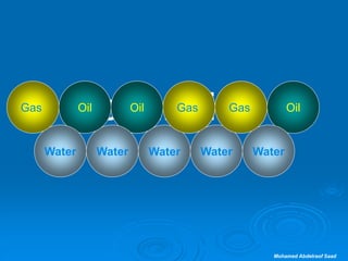
- 1. Mohamed Abdelraof Saad Oil Separation Water GasOil Water Gas Oil Water Gas Oil Water GasOil Water Gas
- 2. Mohamed Abdelraof Saad Phase separation of the production stream is usually performed as soon as is conveniently possible because: * It is technically easier and less costly to process the gas, crude oil, and produced water phases separately. * The produced water is often corrosive. Therefore, removing the water reduces corrosion damage. * Less energy is required to move the separated single phases; so phase separation permits the back pressure to be lowered and this, in turn, increases well production INTRODUCTION
- 3. Mohamed Abdelraof Saad Well Production Rarely is clean oil, ready for sale into a pipeline, produced from an oil well. Natural GasOilWaterSaltSand
- 4. Mohamed Abdelraof Saad Well Production
- 7. Mohamed Abdelraof Saad Com. St. P1-C Glycol Regeneration Unit Fuel Gas Package Oily Water Treatment Unit Well # 4-12 D-103 A D-103 B D-103 C D-105Sump Caisson E-101 14” Sea Line P1-Meadia 14” Sea Line PI-PII PL-101 Z-111 Desander T-101
- 8. WELL FLUIDS AND THEIR CHARACTERISTICS
- 9. Mohamed Abdelraof Saad Crude Oil Crude oil is a complex mixture of hydrocarbons produced in liquid form. The API gravity of crude oil can range from 6 to 50oAPI and viscosity from 5.0 to 90,000 cP at average operating conditions. Color varies through shades of green, yellow, brown, and black.
- 10. Mohamed Abdelraof Saad Condensate This is a hydrocarbon that may exist in the producing formation either as a liquid or as a condensable vapor. Liquefaction of gaseous components of the condensate usually occurs with reduction of well-fluid temperature to surface operating conditions. Gravities of the condensed liquids may range from 50 to 120oAPI and viscosities from 2.0 to 6.0 cP at standard conditions. Color may be water-white, light yellow, or light blue.
- 11. Mohamed Abdelraof Saad Natural Gas A gas may be defined as a substance that has no shape or volume of its own. It will completely fill any container in which it is placed and will take the shape of the container. Hydrocarbon gas associated with crude oil is referred to as natural gas and may be found as "free" gas or as "solution" gas. Specific gravity of natural gas may vary from 0.55 to 0.90 and viscosity from 0.011 to 0.024 cP at standard conditions. Free Gas. Free gas is a hydrocarbon that exists in the gaseous phase at operating pressure and temperature. Free gas may refer to any gas at any pressure that is not in solution or mechanically held in the liquid hydrocarbon. Solution Gas. Solution gas is homogeneously contained in oil at a given pressure and temperature. A reduction in pressure and/or an increase in temperature may cause the gas to be emitted from the oil, whereupon it assumes the characteristics of free gas. Condensable Vapors. These hydrocarbons exist as vapor at certain pressures and temperatures and as liquid at other pressures and temperatures. In the vapor phase, they assume the general characteristics of a gas. In the vapor phase, condensable vapors vary in specific gravity from 0.55 to 4.91 (air = l.0), and in viscosity from 0.006 to 0.011 cP at standard conditions.
- 12. Mohamed Abdelraof Saad Water Water produced with crude oil and natural gas may be in the form of vapor or liquid. The liquid water may be free or emulsified. Free water reaches the surface separated from the liquid hydrocarbon. Emulsified water is dispersed as droplets in the liquid hydrocarbon.
- 13. Mohamed Abdelraof Saad Impurities and Extraneous Materials Produced well fluids may contain such gaseous impurities such as nitrogen, carbon dioxide, hydrogen sulfide, and other gases that are not hydrocarbon in nature or origin. Well fluids may contain liquid or semi-liquid impurities, such as water and paraffin. They may also contain solid impurities, such as drilling mud, sand, and salt.
- 14. CLASSIFICATION OF OIL AND GAS SEPARATORS
- 15. Mohamed Abdelraof Saad Classification by Geometrical Vertical Horizontal double-barrel Horizontal Spherical
- 16. Mohamed Abdelraof Saad Classification by Function Two-phase , (vapor-liquid) . Three-phase (gas-oil-water) .
- 17. Mohamed Abdelraof Saad Classification by Operating Pressure Oil and gas separators can operate at pressures ranging from a high vacuum to 4,000 to 5,000 psi. Most oil and gas separators operate in the pressure range of 20 to 1 ,500 psi. Separators may be referred to as low pressure, medium pressure, or high pressure. Low-pressure separators usually operate at pressures ranging from 10 to 20 up to 180 to 225 psi. Medium-pressure separators usually operate at pressures ranging from 230 to 250 up to 600 to 700 psi. High-pressure separators generally operate in the wide pressure range from 750 to 1,500 psi.
- 18. Mohamed Abdelraof Saad Classification by Application Test Separator A test separator is used to separate and to meter the well fluids. They can be permanently installed or portable (skid or trailer mounted). Production Separator A production separator is used to separate the produced well fluid from a well, group of wells Low-Temperature Separator. The temperature reduction is obtained by the Joule- Thompson effect of expanding well fluid as it flows through the pressure-reducing choke or valve into the separator. Liquids thus recovered require stabilization to prevent excessive evaporation in the storage tanks.
- 19. Mohamed Abdelraof Saad Classification by Application Metering Separator. The function of separating well fluids into oil, gas, and water and metering the liquids can be accomplished in one vessel. These units are available in special models that make them suitable for accurately metering foaming and heavy viscous oil. Foam Separator. Oil and gas separators that handle foaming crude oil. Elevated Separator Separators can be installed on platforms at or near tank batteries or on offshore platforms so that the liquid can flow from the separator to storage or to downstream vessels by gravity. Stage Separators When produced well fluid is flowed through more than one separator with the separators in series, The first separator is referred to as the first-stage separator, the second separator is called the second-stage separator, etc.
- 21. Mohamed Abdelraof Saad Common components Primary Separation Section Secondary or Gravity Settling Section. Mist Extraction or Coalescence Section. Vane-Type extractors Blade-type mist extractors Wire-Mesh or Fibrous mist extractors Liquid Accumulator Section
- 22. Mohamed Abdelraof Saad Primary Separation Section Collecting and removing the bulk of the liquid in the inlet stream. Exploit the momentum of the inlet stream either by creating centrifugal force or change of direction (as in horizontal separators) thus separating most of the incoming liquid.
- 23. Mohamed Abdelraof Saad Secondary or Gravity Settling Section. Gas velocity and turbulence is reduced so that entrained liquid drops can settle out by gravity. Internal baffling is often used to dissipate foams, further reduce turbulence, and accelerate drop removal.
- 24. Mohamed Abdelraof Saad Mist Extraction or Coalescence Section. Vane-Type extractors Blade-type mist extractors Wire-Mesh or Fibrous mist extractors
- 25. Mohamed Abdelraof Saad Liquid Accumulator Section Provides sufficient capacity to handle surges in liquid flow Adequate retention time is necessary to allow for removal of any gas breaking out of solution and, in three-phase separators, for separation of free water and oil. A vortex breaker may be located over the liquid outlet nozzle(s) Recommended minimum liquid levels are: A liquid level of at least two outlet nozzle diameters for gas/liquid interfaces. A liquid level of at least three times the outlet nozzle diameter for liquid/liquid interfaces.
- 26. Mohamed Abdelraof Saad Liquid Accumulator Section
- 27. Mohamed Abdelraof Saad PRIMARY FUNCTIONS OF OIL AND GAS SEPARATORS Removal of Oil from Gas Removal of Gas from Oil Separation of Water from Oil
- 28. METHODS USED TO REMOVE OIL FROM GAS IN SEPARATORS
- 29. Mohamed Abdelraof Saad Density Difference (Gravity Separation) By density difference or force of gravity, settle out of the stream of gas if the velocity of the gas is sufficiently slow. The larger droplets of hydrocarbon will quickly settle out of the gas, but the smaller ones will take longer time . At standard conditions of pressure and temperature, the droplets of liquid hydrocarbon may have a density 400 to 1,600 times that of natural gas. However, as the operating pressure and temperature increase, the difference in density decreases. At an operating pressure of 800 psig, the liquid hydrocarbon may be only 6 to 10 times as dense as the gas. Particles of liquid hydrocarbon with diameters of 100 µm and larger will generally settle out of the gas in most average-sized separators. mist extractors usually are needed to remove smaller particles from the gas.
- 30. Impingement If a flowing stream of gas containing liquid mist is impinged against a surface, the liquid mist may adhere to and coalesce on the surface. After the mist coalesces into larger droplets, the droplets will gravitate to the liquid section of the vessel. If the liquid content of the gas is high, or if the mist particles are extremely fine, several successive impingement surfaces may be required to effect satisfactory removal of the mist.
- 31. Impingement
- 32. Change of Flow Direction When the direction of flow of a gas stream containing liquid mist is changed abruptly, inertia causes the liquid to continue in the original direction of flow. Separation of liquid mist from the gas thus can be effected because the gas will more readily assume the change of flow direction and will flow away from the liquid mist particles. The liquid thus removed may coalesce on a surface or fall to the liquid section below.
- 33. Mohamed Abdelraof Saad Change of Flow Velocity Separation of liquid and gas can be effected with either a sudden increase or decrease in gas velocity. Both conditions use the difference in inertia of gas and liquid. With a decrease in velocity, the higher inertia of the liquid mist carries it forward and away from the gas. The liquid may then coalesce on some surface and gravitate to the liquid section of the separator. With an increase in gas velocity, the higher inertia of the liquid causes the gas to move away from the liquid, and the liquid may fall to the liquid section of the vessel.
- 34. Mohamed Abdelraof Saad Centrifugal Force If a gas stream carrying liquid mist flows in a circular motion at sufficiently high velocity, centrifugal force throws the liquid mist outward against the walls of the container. The liquid coalesces into progressively larger droplets and finally gravitates to the liquid section below. Efficiency of this type of mist extractor increases as the velocity of the gas stream increases. Thus for a given rate of throughput, a smaller centrifugal separator will suffice.
- 35. Mohamed Abdelraof Saad Centrifugal Force
- 36. Mohamed Abdelraof Saad Centrifugal Force and impingement
- 37. Coalescence Coalescing packs afford an effective means of separating and removing liquid mist from a stream of natural gas. The packs use a combination of impingement, change of direction, change of velocity, and coalescence to separate and to remove liquid mist from gas. These packs provide a large surface area for collection and coalescence of the liquid mist .
- 38. Mohamed Abdelraof Saad Filtering Porous filters are effective in the removal of liquid mist from gas in certain applications. The porous material may use the principles of: Impingement change of flow direction change of velocity Generally, filter-type mist extractors will have the highest pressure drop per unit volume of capacity and the coalescing type will have the lowest.
- 39. METHODS USED TO REMOVE GAS FROM OIL IN SEPARATORS
- 40. Mohamed Abdelraof Saad Settling Gas contained in crude oil that is not in solution in the oil will usually separate from the oil if allowed to settle a sufficient length of time. An increase in retention time for a given liquid throughput requires an increase in the size of the vessel and/or an increase in the liquid depth in the separator. Increasing the depth of oil in the separator may not result in increased emission of non-solution gas from the oil because "stacking up" of the oil may prevent the gas from emerging. Optimum removal of gas from the oil is usually obtained when the body of oil in the separator is thin - i.e., when the ratio of surface area to retained oil volume is high.
- 41. Mohamed Abdelraof Saad Agitation Moderate, controlled agitation is helpful in removing non-solution gas that may be mechanically locked in the oil by surface tension and oil viscosity. Agitation usually will cause the gas bubbles to coalesce and to separate from the oil in less time than would be required if agitation were not used. Agitation can be obtained by properly designed and placed baffling.
- 42. Mohamed Abdelraof Saad Baffling An inlet degassing element can be installed on the inlet of the separator to assist in introducing the well fluid into the separator with minimum turbulence and in removing gas from the oil. This type of element eliminates high-velocity impingement of fluid against the opposite wall of the separator. The baffles placed in the separator between the inlet and the oil level spread the oil into thin layers as it flows downward from the inlet to the oil section. This type of baffling is effective in handling foaming oil. Special perforated baffles or tower packing can be used to remove non- solution gas from crude oil. Such baffling or packing provides slight agitation, which allows the gas bubbles to break out of the oil as it flows through the baffles or packing.
- 43. Mohamed Abdelraof Saad Heat Heat reduces surface tension and viscosity of the oil and thus assists in releasing gas . The most effective method of heating crude oil is to pass it through a heated-water bath. through the water bath affords slight agitation, which is helpful in coalescing and separating entrained gas from the oil. A heated-water bath is probably the most effective method of removing foam bubbles from foaming crude oil. A heated-water bath is not practical in most oil and gas separators, but heat can be added to the oil by direct or indirect fired heaters and/or heat exchangers
- 44. Mohamed Abdelraof Saad Chemicals Chemicals that reduce the surface tension of crude oil will assist in freeing non-solution gas from the oil. Such chemicals will appreciably reduce the foaming tendency of the oil and thereby increase the capacity of a separator when foaming oil is handled.
- 45. Mohamed Abdelraof Saad Centrifugal Force Centrifugal force is effective in separating gas from oil. The heavier oil is thrown outward against the wall of the vortex retainer while the gas occupies the inner portion of the vortex.
- 46. Mohamed Abdelraof Saad Separation of Water from Oil In some instances it is preferable to separate and to remove water from the well fluid before it flows through pressure reductions, such as those caused by chokes and valves. The water can be separated from the oil in a three-phase separator by use of chemicals and gravity separation. If the three-phase separator is not large enough to separate the water adequately, it can be separated in a free-water knockout vessel installed upstream or downstream of the separators. If the water is emulsified, it may be necessary to use an emulsion treater to remove it.
- 48. Mohamed Abdelraof Saad Centrifugal Force If a hydrocarbon stream carrying solids flows in a circular motion at sufficiently high velocity, centrifugal force throws the solids outward against the walls of the container. Efficiency of this type of sand extractor increases as the velocity of the hydrocarbon stream increases.
- 49. Mohamed Abdelraof Saad Manifolds for stream collecting
- 50. Mohamed Abdelraof Saad Separator and stage separator Refer to a conventional oil and gas separator. These separating vessels are normally used on a producing lease or platform near the wellhead, manifold, or tank battery to separate fluids produced from oil and gas wells into oil and gas or liquid and gas. They must be capable of handling well fluids "slugs". Therefore, they are usually sized to handle the highest instantaneous rates of flow.
- 51. Mohamed Abdelraof Saad Separator and stage separator
- 52. Mohamed Abdelraof Saad Knockout vessel, drum, or trap may be used to remove only water from the well fluid or to remove all liquid, oil plus water, from the gas. In the case of a water knockout for use near the wellhead, the gas and liquid petroleum are usually discharged together, and the free water is separated and discharged from the bottom of the vessel. A liquid knockout is used to remove all liquid, oil plus water, from the gas. The water and liquid hydrocarbons are discharged together from the bottom of the vessel, and the gas is discharged from the top.
- 53. Mohamed Abdelraof Saad Flash drum or vessel Refers to a conventional oil and gas separator operated at low pressure With the liquid from a higher-pressure separator being "flashed" into it. This flash drum is quite often the second or third stage of separation, with the liquid being discharged from the flash drum to storage.
- 54. Mohamed Abdelraof Saad Expansion vessel The first-stage separator vessel on a low-temperature or cold-separation unit (LTS). This vessel may be equipped with a heating coil to melt hydrates, or a hydrate-preventive liquid (such as glycol) may be injected into the well fluid just before expansion into this vessel.
- 55. Mohamed Abdelraof Saad Expansion vessel LTS Glycol Reach Glycol Flare D-205 Flare Lean Glycol Gas from Slug catcher LP Sales Gas
- 56. Mohamed Abdelraof Saad Expansion vessel 12" Gas outlet 3" Cond. outlet 2" Glycol outlet 10" Inlet Mist Extractor Glycol Coil glycol in glycol out 5.547 M 1.6 M Vortex Breaker Vortex Breaker Design Temp. Design Press. = 120 MMSCFD = -9 oC = 52 Kg/cm2 Capacity
- 57. Mohamed Abdelraof Saad Gas scrubber may be similar to an oil and gas separator. Usually it handles fluid that contains less liquid than that produced from oil and gas wells. Gas scrubbers are normally used in gas gathering, sales, and distribution lines where they are not required to handle slugs or heads of liquid, A "scrubber" can refer to a vessel used upstream from any gas- processing vessel or unit (scrubbers are often used ahead of compressors & glycol systems Applied downstream of field separators to remove entrained and/or condensed liquids to protect the downstream vessel or unit.
- 58. Mohamed Abdelraof Saad Gas scrubber V- 301 X SDV-3004 SDV-3005 V-302C-300 X A-300 SDV-3009 SDV-3007 FCV-3008 Suction C. D. D-204 Flare Flare Discharge To Grid PCV-3006
- 59. Mohamed Abdelraof Saad Filter (gas filter or filter/separator), dust Scrubber, or Coalescer. These separators are designed to remove small quantities of mists, oil fogs, rust, scales, and dust from gases. Typical applications are upstream of compressors, dehydration units Solids are trapped by the filter fibers Liquid droplets are coalesced into large drops that are then separated by gravity. These filter separators are used for final "polishing" and are often preceded or protected, by a conventional scrubber or separator.
- 60. Mohamed Abdelraof Saad Filter (gas filter or filter/separator), dust Scrubber, or Coalescer.
- 61. Mohamed Abdelraof Saad Filter (gas filter or filter/separator), dust Scrubber, or Coalescer. Gas inlet Gas outlet Filter element detail A A View A-A 3 5/8" D. * 3' LG Mist Extractor 38 Filter elements second stage liquid storage First stage liquid storage
- 62. Mohamed Abdelraof Saad Skimmer, liquid hydrocarbon skimmer normally refers to a conventional oil and gas separator operated at low pressure to separate a liquid from another liquid.
- 63. Mohamed Abdelraof Saad Skimmer, liquid hydrocarbon skimmer
- 64. Mohamed Abdelraof Saad Slug catcher a particular separator design able to absorb large volumes at irregular intervals. Usually found on gas gathering system or two-phase pipeline systems. A slug catcher may be a single large vessel or a manifolded system of pipes.
- 65. Mohamed Abdelraof Saad = 14" Emergency = A A B B Section A-A Section B-B Cond. outlet 11.766 M 2.329 M Vortex Breaker 14" Gas outlet 4" Cond. outlet Vortex Breaker 14" Inlet Design Temp. Design Press. = 120 MMSCFD = 45 oC = 99 Kg/cm2 Capacity Slug catcher
- 66. Mohamed Abdelraof Saad Slug catcher
- 67. Mohamed Abdelraof Saad Slug catcher
- 70. Mohamed Abdelraof Saad All of the previous separators use gravity as the separating force. External force fields (electrostatic and centrifugal) can and have been used. However, electrostatic fields are used primarily to break water-in-crude emulsions. Centrifugal force (i.e., a hydrocyclone) is most useful for separating primary oil-in-water dispersions.
- 71. SECONDARY FUNCTIONS OF OIL AND GAS SEPARATORS
- 72. Mohamed Abdelraof Saad Maintain Optimum Pressure on Separator Pressure control valve
- 73. Maintain Liquid Seal in Separator To maintain pressure on a separator, a liquid seal must be effected in the lower portion of the vessel. This liquid seal prevents loss of gas with the oil and requires the use of a liquid-level controller and a valve. Local Level Controller
- 74. Slug Catcher Level Control Slug Catcher Level Control
- 75. Summary for the Function of Separator Internals Purpose of Device or Situation where Device should not be used Internal Device a- remove liquid mist from gas.1- Mist Pad b- break oil-water emulsion. c- not used where hydrate, wax, or dirt may be present. a- separate liquid from gas.2- Deflector Plate b- used in all services. a- remove liquid mist from gas.3- Coalescing Plate b- separate oil from water. c- not used where hydrate, corrosion, wax or dirt present.
- 76. Summary for the Function of Separator Internals a- remove liquid mist from gas.4- Straightening Vanes b- separate oil from water. c- not used where hydrate, corrosion, wax or dirt present. a- remove solid particles from gas or liquid.5- Filter Elements b- separate oil from water. c- remove mist from gas. d- not used where wax or hydrate may be present. a- separate oil from water.6- Coalescing Materials b- not used where wax may be present.
- 77. Summary for the Function of Separator Internals a- separate gas from liquid.7- Centrifugal Devices b- not used where wax or dirt may be present. c- not used with intermittent gas flow. a- usually used in large gas-liquid vessels where waves occur. 8- Horizontal Baffles a- should be used on all liquid outlet nozzles in gas-liquid separators 9- Vortex Breakers b- are not needed if vessel is full of liquid a- should be used when internal level control float is used.10- Float Shield a- used only when solids may be present.11- Water Jets and Sand Cones
- 78. SELECTION AND APPLICATION OF SEPARATORS AND SCRUBBERS
- 79. Vertical Oil and Gas Separators Applications: 1. Well fluids having a high liquid/gas ratio. 2. Well fluids containing appreciable quantities of sand, mud, and similar finely divided solids. 3. Installations with horizontal space limitations but with little or no vertical height limitations 4. Upstream of other field process equipment that will not perform properly with entrained liquid in the gas. 5- Where economics favors the vertical separator.
- 80. Horizontal Oil and Gas Separators Applications 1. Liquid/liquid separation in three-phase separator installations to obtain more efficient oil/water separation. 2. Separating foaming crude oil where the larger liquid/gas contact area of the horizontal vessel . 3. Installations where vertical height limitations indicate the use of a horizontal vessel. 4. Well fluids with a high GOR. 5. Well with relatively constant flow rate and with little or no liquid heading or surging. 6. Where portable units (either skid or trailer mounted) are required for either test or production use. 7. Where economics favors the horizontal separators.
- 81. Spherical Oil and gas Separators applications Well fluids with high GOR's, constant flow rate and no liquid slugging or heading. Installations where both vertical and horizontal space and height limitations exist. Downstream of process units — such as glycol dehydrators and gas sweeteners — to scrub expensive process fluids, such as glycol . Installations where economics favors the spherical separator.
- 82. Mohamed Abdelraof Saad Gas Scrubbers Some of the uses for gas scrubbers are to clean gas: For fuel for healers, boilers, steam generators and engines. Upstream of compressors. Upstream of dehydrators . Upstream of gas distribution systems. Upstream of and in gas transmission lines to remove liquid, dust, and scale. Upstream and / or downstream of pressure regulation stations. Downstream of gas-transmission-line compressor stations to remove lubricating oil from the line.
- 83. POTENTIAL PROBLEMS IN OIL AND GAS SEPARATORS
- 84. Mohamed Abdelraof Saad Separating Foaming Crude Oil When pressure is reduced on certain types of crude oil, tiny spheres (bubbles) of gas are encased in a thin film of oil when the gas comes out of solution This may result in foam. The main factors that assist in "breaking" foaming oil are settling, agitation (baffling), heat, chemicals, and centrifugal force.
- 85. Mohamed Abdelraof Saad Paraffin Paraffin deposition in oil and gas separators reduces their efficiency and may render them inoperable by partially filling the vessel and/or blocking the mist extractor and fluid passages. Paraffin can be effectively removed from separators by use of steam or solvents. The best solution is to prevent initial deposition in the vessel by heat or chemical treatment of the fluid upstream of the separator. Another deterrent, successful in most instances, involves the coating of all internal surfaces of the separator with a plastic for which paraffin has little or no affinity.
- 86. Mohamed Abdelraof Saad Sand, Mud, Salt If sand and other solids are continuously produced in appreciable quantities with well fluids, they should be removed before the fluids enter the pipelines Medium grained sand in small quantities can be removed by settling in an oversized vertical vessel with a conical bottom and by periodically draining the residue from the vessel. Desander Salt may be removed by mixing water with the oil, and after the salt is dissolved, the water can be separated from the oil and drained from the system.
- 87. Mohamed Abdelraof Saad Corrosion Produced well fluids can be very corrosive and cause early failure of equipment The two most corrosive elements are hydrogen sulfide and carbon dioxide . These two gases may be present in the well fluids in quantities from a trace up to 40 to 50% of the gas by volume
- 88. Mohamed Abdelraof Saad Flow Variations Separators should be sized to handle the maximum flow rate expected during the predicted life of the separator. Separators must also be capable of handling sudden slugs of liquid.
- 89. Mohamed Abdelraof Saad START-UP PROCEDURE OPERATION If the vessel is empty, close a block valve in each liquid outlet line from the vessel to prevent possible leakage through a control valve in the liquid line . If the vessel has a pressure controller, it should be set at about 75% of the normal control pressure, and slowly bring it up to a normal pressure after the vessel is in service. If the vessel has low level shutdown devices, they must be deactivated or liquid must be added to the vessel to a point above the low level devices. Check the flow lines out of the vessel to see that each stream leaving the vessel flows in the proper direction. Slowly open the inlet stream to the vessel. When the liquid level reaches the range of level controller, place level controllers in service and open the block valves that were closed in step 1. Adjust level and pressure controllers to stabilize their operation
- 90. Mohamed Abdelraof Saad SHUTDOWN PROCEDURE Close a valve in the inlet stream. 2a. Close valves in liquid outlet line to prevent liquid from leaking out. 2b. If the vessel must be drained, open the by-pass line on the level control valves . Close block valves in the liquid outlet lines after draining. If the vessel must be depressurized, close a block valve in the gas outlet line. Depressurize the vessel by opening a valve in the line from the vessel to the vent or blow down system. If possible, leave a small positive pressure on the vessel while it is shutdown to prevent air from entering so it will not have to be purged prior to start-up.
- 91. Mohamed Abdelraof Saad ROUTINE OPERATION Routine operating checks are observing the various level, pressure, temperature and flow control instruments to see that they are controlling within the proper range. Diaphragm-operated control valves should be stroked occasionally to see that they will fully open and close without restriction. Gauge glasses should be drained periodically to prevent scale from accumulating in the lines or gauge valves and causing them to show false levels. If the vessel has filters or coalescing chambers, the pressure drop cross them should be observed for an increase which indicates a build-up of solid particles, and the need to replace or clean them
- 92. MAINTENANCE CONSIDERATIONS FOR OIL AND GAS SEPARATORS
- 93. Mohamed Abdelraof Saad Periodic Inspection In refineries and processing plants, it is normal practice to inspect all pressure vessels and piping periodically for corrosion and erosion. In the oil fields, this practice is not generally followed, and equipment is replaced only after actual failure. This policy may create hazardous conditions for operating personnel and surrounding equipment. It is recommended that periodic inspection schedules for all pressure equipment be established and followed to protect against failures.
- 94. Mohamed Abdelraof Saad Installation of Safety Devices All safety relief devices should be installed as close to the vessel as possible The discharge from safety devices should not cause danger to personnel or other equipment.
- 95. Mohamed Abdelraof Saad Safety Heads (Rupture Disks) The discharge from a safety head should be open and without restriction. A valve should not be used between the safety head and the separator because it may inadvertently be closed. Water should not be allowed to accumulate on top of the rupture disk because ice could form and alter the rupture characteristics of the disk. Pressure relief valves may corrode and leak or may "freeze" in the closed position. They should be checked periodically and replaced if not in good working condition.
- 96. Mohamed Abdelraof Saad Mist Extractors Some mist extractors in oil and gas separators require a drain or liquid down-comer to conduct liquid from the mist extractor to the liquid section of the separator. This drain will be a source of trouble when pressure drop through the mist extractor becomes excessive. If the pressure drop across the mist extractor, measured in inches of oil exceeds the distance from the oil level in the separator to the mist extractor, the oil will flow from the bottom of the separator up through the mist-extractor drain and out with the gas. This condition may be aggravated by partial plugging of the mist extractor with paraffin or other foreign material. separators of advanced design have used mist extractors that do not require drains or down-comers.
- 97. Mohamed Abdelraof Saad Low Temperatures Separators should be operated above hydrate- formation temperatures. Otherwise hydrates may form in the vessel and partially or completely plug it Steam coils can be installed in the liquid section of oil and gas separators to melt hydrates that may form there.
- 98. Mohamed Abdelraof Saad Corrosive Fluids A separator handling corrosive fluid should be checked periodically to determine whether remedial work is required. Periodic hydrostatic testing is recommended, especially if the fluids being handled are corrosive. ultrasonic thickness indicators calculates the maximum allowable working pressure from the remaining metal thickness. This should be done yearly offshore and every two to four years onshore.
- 99. Mohamed Abdelraof Saad Paraffin A separator handling paraffin-based oil may need to be steamed periodically to prevent plugging and a resultant decrease in capacity. The reduction in capacity often results in liquid carryover in the gas or discharge of excessive gas with the liquid.
- 100. Mohamed Abdelraof Saad Throttling Discharge of Liquid Throttling discharge of small volumes of liquid from separators normally should be avoided. Throttling may cause erosion or wire drawing of the inner valves and seats of the liquid-dump valves and may erode the dump-valve bodies to the extent that they may burst at or below rated working pressures. However, throttling discharge may be necessary because processing units, such as lower-pressure separators or stabilization units, downstream of the separator may require relatively steady flow. Liquid-discharge control valves on separators should be sized for the volume of liquid the separator must handle. Such valves usually should be smaller than the lines in which they are installed. Reduced inner valves can be used to size the valve properly to minimize wire drawing during throttling service.
- 101. Mohamed Abdelraof Saad Pressure Gauges Pressure gauges and other mechanical devices on separators should be tested for accuracy at regular intervals. Isolating valves should be used so that pressure gauges can be easily removed for testing, cleaning, repairs, or replacement.
- 102. Mohamed Abdelraof Saad Gauge Glasses Gauge glasses should be kept clean so that the liquid level observed in the sight glass indicates at all times the true liquid level in the separator. Periodic flushing of the gauge glass or cleaning with special solvents and swabs is recommended.
- 103. Mohamed Abdelraof Saad Cleaning of Vessels It is recommended that all separator vessels be equipped with man-ways, cleanout openings, and/or washout connections so that the vessels can be cleaned periodically. Larger vessels can be equipped with man-ways to facilitate their cleaning. Smaller vessels can be equipped with hand-holes and/or washout connections so that they can be easily cleaned or washed out periodically.
- 104. Mohamed Abdelraof Saad Maintenance Recommendations Maintenance should include the following: Daily Check liquid levels. Check pressures and temperatures. Replace broken gauge glasses and pressure gauges. Periodically Lubricate valves. Check dump valves. Check level controllers. Check pressure controls. Yearly - check pressure-relief valves.
- 105. Mohamed Abdelraof Saad TROUBLESHOOTING ADVICES Possible causes for the more common problems are listed: Low liquid level Fluid dump valve opening too wide. Drain valve open or leaking. No fluid entering. High liquid level Fluid dump valve closed or plugged. Block valve around dump valve closed. Inlet valve to next vessel closed. Separator overloaded. Low pressure in separator Leaking safety-relief valve. Inlet valve closed. High pressure in separator Valves downstream of separator closed. All the oil going out gas line Dump valve not open. Block valve closed on piping to tank. Separator or piping plugged.
- 106. Mohamed Abdelraof Saad TROUBLESHOOTING ADVICES Mist going out gas line Vessel too small. Plugged mist extractor. Improper liquid level ( too high or too low ). Foaming problem. Free gas going out oil valve Too low level in separator. Dump valve not seating. No vortex breaker or breaker plugged or damaged. Condensate and water not separating in 3-phase separator Adjustable weir out of adjustment. Not enough retention time.. Leak in adjustable weir. Diaphragm operated dump valve not opening - Supply gas failure. - Broken valve stem. - Plugged tubing. - Ruptured diaphragm. - Stopped up vent in upper case
- 109. Mohamed Abdelraof Saad Manifolds for pressures up to 100 bar fully equipped