
Recommended
Recommended
More Related Content
Similar to Remote Video Monitoring System Using Raspberry Pi 3 and GPRS Module
Similar to Remote Video Monitoring System Using Raspberry Pi 3 and GPRS Module (20)
More from rahulmonikasharma
More from rahulmonikasharma (20)
Recently uploaded
Recently uploaded (20)
Remote Video Monitoring System Using Raspberry Pi 3 and GPRS Module
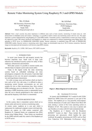
- 1. International Journal on Recent and Innovation Trends in Computing and Communication ISSN: 2321-8169 Volume: 5 Issue: 10 172 – 176 _______________________________________________________________________________________________ 172 IJRITCC | October 2017, Available @ http://www.ijritcc.org _______________________________________________________________________________________ Remote Video Monitoring System Using Raspberry Pi 3 and GPRS Module Mrs. S.N.Kale ME Electronics, Electronics Dept PVPIT Budhgaon Sangli, India Snkale.eln@pvpitsangli.edu.in Mr. R.D.Patil Asso. Professor, Electronics Dept., PVPIT Budhgaon Sangli,India prajaram2@gmail.com Abstract—Now a day’s security has prime importance in different areas such as home security, monitoring of remote areas etc. with advancement in embedded system and wireless technology, it is possible to build a remote area monitoring system with low cost. This paper represents a system implemented by using Raspberry Pi 3 and GPRS module. Transmitter section is implemented at remote area where images are captured by using USB camera interfaced with Raspberry pi. Images are compressed by software programming using libjpeg library and uploaded to HTTP server via SIM900A/800 GSM/GPRS module. Internet connection is established using PPP stack of SIM900A/800 GSM/GPRS module. Receiver section is monitoring center where images are downloaded using 3g or Wi-Fi wireless connection. Received images are decompressed and streamed on web browser using MJPG streamer. Keywords- Raspberry Pi 3, GPRS, USB Camera, PPP, MJPG streamer __________________________________________________*****_________________________________________________ I. INTRODUCTION In recent years human life and property security has becomes important issue. Small scale to large scale industries has introduced security system for safety of their employee, infrastructure and amenities. With older system it is possible to monitor nearby area with the help of computer system and coaxial cables. Today in this digital world, the video monitoring systems based on embedded technology are more advantageous compared to the old systems. It provides high performance at low cost ,low power consumption, compact size and long-distance transmission. For wide coverage areas and locations which are hard to wire such as hill, river side areas, it is difficult to place a monitoring system because environments are not well suitable for wire or fiber transmission lines. Here wireless GPRS technology gives an alternative for this. The cost of operating a GPRS monitoring system is substantially lower, since the cost is directly proportional to the volume of the data and the frequency with which it is transmitted. II. SYSTEM ARCHITECTURE In this system, there is transmitter section which act as remote centre and receiver section as monitoring centre. At remote centre, raspberry pi is core part which is replacement for traditional computer system with hard disk. Frames are capture via USB camera connected with Raspberry Pi. Captured frames are compressed into JPEG format using Libjpeg library . These frames are transferred by the GPRS network under the control of the Raspberry pi to HTTP server. Figure 1. Block diagram of overall system III. RASPBERRY PI 3 SYSTEM At remote side RASPBERRY PI 3 model B with1.2GHz Quad-Core ARM Cortex-A53 processor is core part of the system. The raspberry pi is a very powerful, minicomputer with the dimensions of credit card. It Boots from Micro SD card, running a version of the Linux operating system or Windows 10 IoT. This system is very easy to operate and user friendly as it comes with GUI and command prompt. The Raspberry pi 3 features with the Broadcom BCM2837 “system on chip,”. These include the central processing unit (processor), which handles the main workload; the graphics processing unit (GPU) such as Dual Core VideoCore IV® Multimedia Co-Processor which USB camera SIM900A /800 GPRS module HTTP Server Internet WiFi/ Internet connection Computer System (MJPG Streamer) Raspberry Pi 3 (BCM 2837)
- 2. International Journal on Recent and Innovation Trends in Computing and Communication ISSN: 2321-8169 Volume: 5 Issue: 10 172 – 176 _______________________________________________________________________________________________ 173 IJRITCC | October 2017, Available @ http://www.ijritcc.org _______________________________________________________________________________________ provides Open GL ES 2.0, hardware-accelerated OpenVG, and 1080p30 H.264 high-profile decode , which accelerates the process of producing the complicated graphics to see on screen; and the random access memory (RAM) 1GB LPDDR2 memory module. The Raspberry Pi 3 has four USB ports, allowing connect it to keyboards, mice, WiFi dongles, USB camera , USB sticks containing files, 4 Pole stereo output and composite video port and Micro SD port for loading operating system and storing data The Raspberry Pi 3 features the same 40-pin general- purpose input-output (GPIO) header as all the Pis going back to the Model B+ and Model A+. Any existing GPIO hardware will work without modification; the only change is a switch to which UART is exposed on the GPIO’s pins, but that’s handled internally by the operating system. A. Installation and booting of Raspberry Pi 3 Raspberry Pi doesn’t come with an operating system. Operating systems such as the recommended Raspbian, ArchLinux, Windows 10 IOT Core, Risc OS and even Android are available forraspberry pi 3 . The Raspberry Pi has a large suite of programming languages. Pre-installed is the GCC compilation software. This allows to program in languages such as C, C++, C#. The main programming language is Python with both version 2.7 and 3.2 . For shell scripting, Bash is available. Raspbian is the Foundation’s official supported operating system. It can be installed with NOOBS or writing image of operating system on sd card using WIN32DISKIMAGER utility in computer system with Windows operating system Raspbian comes pre-installed with plenty of software for education, programming and general use. It has Python, Scratch, Sonic Pi, Java, Mathematica and more. After installation, pi is booted using SD card and configured by using raspi-config configuration menu. Figure 2. Configuration tool window By selecting different options required functions are enabled or disabled. EXPAND FILE SYSTEM option is enabled so that all of the SD card storage is available to the OS. Password can be changed using CHANGE USER PASSWORD option. With ENABLE BOOT TO DESKTOP/SCRATCH, booting into a desktop environment, Scratch, or the command line is selected. INTERNATIONALISATION Options sets up the language and regional settings to match location. In advanced option SERIAL option is enabling for shell and kernel messages on the serial connection. IIII. APPLICATION PROGRAM FOR CAPTURE, COMPRESSION, DECOMPRESSION OF FRAMES A. Remote centre Application program using c language is written to capture frames and compress frames using libjpeg library. This progam is based on Video For Linux Two API. Using the V4L2 structure, the video device is packaged as a file that can be read and written directly. The camera device driver workflow is as follows, 1) Open the video device; 2) Read the device information 3) Allocate the frame buffer for the device; 4) Capture the image through V4L2 interface. 5) YUV to RGB conversion 6) JPEG compression 7) Close the video device 1) Open the Capture Device. V4L2 drivers are implemented as kernel modules, loaded manually by the system administrator or automatically when a device is first opened. The driver modules plug into the "videodev" kernel module. It provides helper functions and a common application interface. To open and close V4L2 devices applications use the open() and close() function, respectively. Devices are programmed using the ioctl() function In Linux, default capture devide is generally /dev/video0, but for USB webcams, the index will vary accordingly. The Linux kernel supports UVC (USB video device class) based cameras. UVC is a USB device class that describes devices capable of streaming video like webcams, digital camcorders, transponders, analog video converters, television tuners, and still-image cameras. In this system Logitech c 170, 5 Mp web camera is used which is UVC based so that there is no requirement for drivers needed to capture images from the camera. 2) Read the device information: A) Querying Capabilities
- 3. International Journal on Recent and Innovation Trends in Computing and Communication ISSN: 2321-8169 Volume: 5 Issue: 10 172 – 176 _______________________________________________________________________________________________ 174 IJRITCC | October 2017, Available @ http://www.ijritcc.org _______________________________________________________________________________________ Because V4L2 covers a wide variety of devices not all aspects of the API are equally applicable to all types of devices. The VIDIOC_QUERYCAP ioctl is available to check if the kernel device is compatible with this specification, and to query the functions and I/O methods supported by the device. B) Image Formats The V4L2 API was primarily designed for devices exchanging image data with applications. The v4l2_pix_format structure defines the format and layout of an image in memory. V4L2 includes several such formats. In V4L2 each format has an identifier which looks like PIX_FMT_XXX, defined in the videodev.h header file. In this system YUV format is selected YUV is the format native to TV broadcast and composite video signals. It separates the brightness information (Y) from the color information (U and V or Cb and Cr). Secondary in the YUV format the U and V components usually have lower resolution than the Y component. V4L2 provides an easy interface to check the image formats and colorspace that webcam supports and provide. v4l2_format sturcture is to be used to change image format. C) memory mapping IO method: The V4L2 API defines several different I/O methods to read from or write to a device. Streaming is an I/O method where only pointers to buffers are exchanged between application and driver, the data itself is not copied. Memory mapping is primarily intended to map buffers in device memory into the application’s address space. There are two streaming methods: memory mapped and user pointer. 3) Allocate the frame buffer for the device: A) Request buffers: A buffer contains data exchanged by application and driver using Streaming I/O methods. v4l2_requestbuffers is used to allocate device buffers. To allocate device buffers, applications call the VIDIOC_REQBUFS ioctl with the desired number of buffers and buffer type. B) Query Buffer After requesting buffer from the device, we need to query the buffer in order to get raw data. Before applications can access the buffers they must map them into their address space with the mmap() function. The location of the buffers in device memory can be determined with the VIDIOC_QUERYBUF ioctl. Applications should free the buffers as soon as possible with the munmap() function. 4. Capture the image through V4L2 interface. After querying the buffer, the frame is captured and saved in the buffer. To start and stop capturing or output applications call the VIDIOC_STREAMON and VIDIOC_STREAMOFF ioctl. Conceptually streaming drivers maintain two buffer queues, an incoming and an outgoing queue. The queues are organized as FIFOs, buffers will be output in the order enqueued in the incoming FIFO, and were captured in the order dequeued from the outgoing FIFO. 5. YUV to RGB conversion captured frames are converted into RGB format. YUV format are used for television broadcast however many displays (almost all DVI inputs) only except RGB. 6. JPEG compression The JPEG compression encoding scheme is used in this system which is based on the DCT (Discrete Cosine Transform) sequence. The JPEG encoding under Linux can use the library Libjpeg, which is used under linux standard library, and its function is to compress the picture in accordance with a certain percentage of compressed into JPEG format pictures. In this system libjpeg8 library package is installed using sudo apt-get install libjpeg8-dev on command line. 7. To close V4L2 devices applications use the close() function. B. Monitoring centre Received images are decompressed by libjpeg library using application program. V. PROGRAM DESIGN FOR NETWORKING A. sim900A/800 GSM/GPRS module GSM/GPRS Modem-RS232 is built with Dual Band GSM/GPRS engine- SIM900A, works on frequencies 900/ 1800 MHz. It features GPRS multi-slot class 10/class 8(optional) and support GPRS coding schemes CS-1,CS-2, CS-3,CS-4.The Modem is coming with RS232 interface, which allows connect PC as well as microcontroller with RS232 Chip(MAX232). The baud rate is configurable from 9600-115200 through AT command. The GSM/GPRS Modem is having internal TCP/IP stack to enable to connect with internet via GPRS. It is suitable for SMS, Voice as well as DATA transfer application in M2M interface. There is GPRS data transfer (PPP or TCP or UDP) in progress. In this case, power consumption is related with network settings (e.g. power control level), uplink / downlink data rates and GPRS configuration (e.g. used multi-slot settings).The onboard Regulated Power supply allows to connect wide range unregulated power supply. Using this
- 4. International Journal on Recent and Innovation Trends in Computing and Communication ISSN: 2321-8169 Volume: 5 Issue: 10 172 – 176 _______________________________________________________________________________________________ 175 IJRITCC | October 2017, Available @ http://www.ijritcc.org _______________________________________________________________________________________ modem can make audio calls, SMS, Read SMS; attend the incoming calls and internet through simple AT commands. The modem needed only 3 wires (Tx, Rx, GND) except Power supply to interface with microcontroller/Host PC. Internet connection on Raspberry Pi is established through a GPRS cellular data connection using GPRS module. The Raspberry Pi serial port consists of two signals (a 'transmit' signal, TxD and a 'receive' signal RxD) made available on the GPIO header. On the Raspberry Pi 3 serial port is called as /dev/ttyAMA0 and is by default mapped to the GPIO pins 14 and 15. Figure 3. Interfacing of USB camera and GPRS module to Raspberry Pi B. Internet connectivity using GSM / GPRS Modem (SIM900A/800) and PPP protocol PPP is most commonly used data link protocol. It is used to connect the Home PC to the server of ISP via a modem. PPP is the protocol used for establishing internet links over dial-up modems, DSL connections, and many other types of point-to-point links. The pppd daemon works together with the kernel PPP driver to establish and maintain a PPP link with another system (called the peer) and to negotiate Internet Protocol (IP) addresses for each end of the link. Pppd can also authenticate the peer and/or supply authentication information to the peer. PPP can be used with other network protocols besides IP. Chat is a program that can perform simple handshaking between a PPP client and server during connection setup, such as exchange usernames and passwords. Chat is also responsible for causing your modem to dial the ISP's phone number and other simple tasks. Chat itself is automatically invoked by pppd when started. A simple shell script invokes chat to handle the negotiation. Script file should be placed in the /etc/ppp (as root). Required and previlaged options are defined in script file which is placed in /etc/ppp/peers directory To establish internet connection following command will be executed using terminal: pppd call chat_file C. Internet connectivity at monitoring centre At receiver side we can use 3g, 4g network or Wi-Fi connection to connect and access HTTP server. IVI. UPLOADING AND DOWNLOADING IMAGES TO/FROM HTTP SERVER Captured images are uploaded on HTTP server using curl utility. Shell script program is used to connect and post images to HTTP server. At monitoring side images are downloaded by curl utility from HTTP server. MONITORING AT RECEIVER SIDE At receiver side we have computer system with Linux based Ubuntu operating system which is used to receive and display jpeg images continuously by using application programs. Images are received from HTTP server using client utility such as curl and images are displayed using MJPG Streamer program. MjpgStreamer It is a simple utility to stream jpeg images or video via HTTP. MJPG-streamer", is a command line application that copied JPG-frame from a single input plug-in to multiple outputs plug-in. It can be used to stream JPEG files over an IP-based network from the webcam to a viewer like Firefox, and Video lan client or even to a Windows Mobile device running the TCPMP-Player. It is light and utilizes less CPU hence ideal for embedded devices and regular servers. It recovers JPG images from UVC-compatible webcams, system files or other input plugins and distributes them as M-JPEG via HTTP to browsers, VLC or others. We can use input_file plugin to collect images from folder, ouput_http plugin to stream files and output plugin to store JPEG images of the input plug-in in a specified folder. Figure 4. streaming of video at receiver side using MJPG Streamer
- 5. International Journal on Recent and Innovation Trends in Computing and Communication ISSN: 2321-8169 Volume: 5 Issue: 10 172 – 176 _______________________________________________________________________________________________ 176 IJRITCC | October 2017, Available @ http://www.ijritcc.org _______________________________________________________________________________________ VII. CONCLUSION This implemented system is useful for remote area monitoring system. RGB frame is compressed using libjpeg library used in application program. RGB frame has size up to 233Kib for 320x240 pixels which is compressed at different qualities. Due to limited bandwidth of GPRS network lower value of jpeg quality should be selected. To get clear image minimum 40% jpeg quality is desirable. For 40% quality, image is compressed with near about 75 compression ratio which reduces image size as 2-3kb. This size is tolerated for transmission with GPRS network. As jpeg quality of image increases, image size also increases. Images are available at receiver side which can be used in future. Images are also available on server; hence those images are downloaded afterword if failed to download. At monitor client, images are decompressed by libjpeg library and then streamed using Mjpg streamer utility. With 100% jpeg quality, image size is enhanced with 20-25kb size. Due to low bandwidth of GPRS network and use of dynamic IP, cost of the system will be effectively reduced. After compression, jpeg images are uploaded to HTTP server in 5-7 seconds. This may vary according to strength of network signal. 3G or Wi-Fi wireless technology can be used at remote station which increases cost but gives better result for remote monitoring. REFERENCES [1] Yongqiang Zhang 1, Guozhen Zhao 2, Yongjian Zhang “Design of a remote image monitoring system based on GPRS” 2009 International Conference on Machine Learning and Computing IPCSIT vol.3 (2011) © (2011) IACSIT Press, Singapore [2] Lihui Zhao,Chunbao Huo and Hongzhe Yang “The Design of Remote Video Monitoring System Based on S3C2416 and GPRS”, IEEE 2012, International Conference on System Science and Engineering June 30-July 2, 2012, Dalian, China [3] Nagaraja G. and Sharada P.N. “Design of Remote Security System Using Embedded Linux Based Video Streaming” International Journal of Computing Academic Research (IJCAR) ISSN 2305-9184 Volume 2, Number 2 (April 2013), pp. 50-56 [4] Sanjana Prasad, P.Mahalakshmi, A.John Clement Sunder, R.Swathi “Smart Surveillance Monitoring System Using Raspberry PI and PIR Sensor” (IJCSIT) International Journal of Computer Science and Information Technologies, ISSN:0975-9646 Vol. 5 (6) , 2014, 7107- 7109 [5] Ruturaj Shete, Mayuri Sabale “Video surveillance using raspberry Pi architecture” The International Daily journal ISSN 2278 – 5469 EISSN 2278 – 5450 © 2015 pgno 37-43 [6] https://linux.die.net/man/8/pppd [7] https://www.raspberrypi.org [8] http://spellfoundry.com/2016/05/29/configuring-gpio- serial-port-raspbian-jessie-including-pi-3/ [9] http://www.mit.edu/afs.new/sipb/user/ssen/src/curl- 7.11.1/docs/curl.html