
Recommended
More Related Content
What's hot
What's hot (20)
Similar to Hydraulic Principles & Applications
Similar to Hydraulic Principles & Applications (20)
More from Sahl Buhary
Recently uploaded
Recently uploaded (20)
Hydraulic Principles & Applications
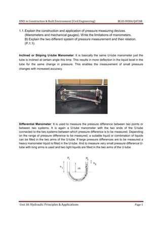
- 1. HND in Construction & Built Environment (Civil Engineering) BCAS DOHA QATAR Unit 38: Hydraulic Principles & Applications Page 1 1.1.Explain the construction and application of pressure measuring devices. (Manometers and mechanical gauges). Write the limitations of manometers. B) Explain the two different system of pressure measurement and their relation. (P.1.1) Inclined or Sloping U-tube Manometer: It is basically the same U-tube manometer just the tube is inclined at certain angle this time. This results in more deflection in the liquid level in the tube for the same change in pressure. This enables the measurement of small pressure changes with increased accuracy. Differential Manometer: It is used to measure the pressure difference between two points or between two systems. It is again a U-tube manometer with the two ends of the U-tube connected to the two systems between which pressure difference is to be measured. Depending on the range of pressure difference to be measured, a suitable liquid or combination of liquids can be filled in the two arms of the U-tube. If large pressure differences are to be measured a heavy manometer liquid is filled in the U-tube. And to measure very small pressure difference U- tube with long arms is used and two light liquids are filled in the two arms of the U-tube
- 2. HND in Construction & Built Environment (Civil Engineering) BCAS DOHA QATAR Unit 38: Hydraulic Principles & Applications Page 2 Mechanical Pressure Measurement Gauges Mechanical Pressure Measurement Devices do not read pressure of any system by deflection of liquid level in some sort of tube. Instead they use some solid object, such as, tube, plate, or diaphragm to measure pressure. The system whose pressure is to be measured is connected to the deflecting object. Any change in pressure causes the object to deflect and this deflection is mechanically amplified, by using a suitable gear and linkage mechanism, and indicated on the calibrated dial. Gauge: The Bourdon Guage has a coiled tube whose one end is connected to the system under consideration and other end is sealed. With the application of the pressure in the tube it straightens up causing deflection of the sealed end. The sealed end is connected to the indicating needle through a gear and linkage mechanism. The deflection of the sealed end results in movement of the needle which moves on a calibrated dial. Bourdon gauges can be used to measure a wide range of pressures. Diaphragm Gauge: Similar to the Bourdon Gauge, but has a Diaphragm which deflects on pressure changes and the deflection is indicated on the calibrated scale. Bellows Gauge: In such gauges indicating needle is driven by the deflection of bellows chamber. This gauge is suitable for measurement of very low pressures. Pressure Transducers Pressure Transducers use an electrical system in conjunction with mechanical gauges to convert the deflection due to pressure changes into electrical signals. Pressure Transducers are useful to measure pressures continuously such that the electrical signal supplied to some
- 3. HND in Construction & Built Environment (Civil Engineering) BCAS DOHA QATAR Unit 38: Hydraulic Principles & Applications Page 3 control system can be used to monitor the pressure variations. Some typical types of pressure transducers can be capacitive, magnetic, resistive, or piezoelectric. Limitations of manometers While it can be adapted to measure very small pressure differences, it can not be used conveniently for large pressure differences - although it is possible to connect a number of manometers in series and to use mercury as the manometric fluid to improve the range. (limitation) A manometer does not have to be calibrated against any standard; the pressure difference can be calculated from first principles. ( Advantage) Some liquids are unsuitable for use because they do not form well-defined menisci. Surface tension can also cause errors due to capillary rise; this can be avoided if the diameters of the tubes are sufficiently large - preferably not less than 15 mm diameter. (limitation) A major disadvantage of the manometer is its slow response, which makes it unsuitable for measuring fluctuating pressures.(limitation) It is essential that the pipes connecting the manometer to the pipe or vessel containing the liquid under pressure should be filled with this liquid and there should be no air bubbles in the liquid.(important point to be kept in mind) DYNAMIC PRESSURE SYSTEMS Dynamic pressure systems are more complex than static systems and can be more difficult to measure. In a dynamic system, pressure typically is defined using three different terms. The first pressure we can measure is static pressure. This pressure is the same as the static pressure that is measured in a static system. Static pressure is independent of the fluid movement or flow. As with a static system the static pressure acts equally in all directions. The second type of pressure is what is referred to as the dynamic pressure. This pressure term is associated with the velocity or the flow of the fluid. The third pressure is total pressure and is simply the static pressure plus the dynamic pressure. STEADY-STATE DYNAMIC SYSTEMS Care must be taken when measuring dynamic system pressures. For a dynamic system, under steady- state conditions, accurate static pressures may be measured by tapping into the fluid stream perpendicular to the fluid flow. For a dynamic system, steady-state conditions are defined as no change in the system flow conditions: pressure, flow rate, etc. Figure illustrates a dynamic system with a fluid flowing through a pipe or duct. In this example a static pressure tap is located in the duct wall at point A. The tube inserted into the flow is called a Pitofit tube. The Pitot tube measures the total pressure at point B in the system. The total pressure measured at this point is referred to as the stagnation pressure. The stagnation pressure is the value obtained when a flowing fluid is decelerated to zero velocity in an isentropic (frictionless) process. This process converts all of the energy from the flowing fluid into a pressure that can be measured. The stagnation or total pressure is the static pressure plus the dynamic pressure. It is very difficult to accurately measure dynamic pressures. When dynamic
- 4. HND in Construction & Built Environment (Civil Engineering) Unit 38: Hydraulic Principles & Applications pressure measurement is desired, the total and static pressures are measured and then subtracted to obtain the dynamic pressure. Dynamic pressures can be used t rates in dynamic systems. HND in Construction & Built Environment (Civil Engineering) ydraulic Principles & Applications pressure measurement is desired, the total and static pressures are measured and then subtracted to obtain the dynamic pressure. Dynamic pressures can be used to determine the fluid velocities and flow BCAS DOHA QATAR Page 4 pressure measurement is desired, the total and static pressures are measured and then subtracted to o determine the fluid velocities and flow
- 5. HND in Construction & Built Environment (Civil Engineering) BCAS DOHA QATAR Unit 38: Hydraulic Principles & Applications Page 5 1.2. Determine the total pressure on a circular plate of diameter 2m which is placed vertically in water in such a way that the centre of plate is 4m below the free water surface. Find the position of centre of pressure also. (P1.2) = 2 ℎ = 4 = = 22 7 × 1 = 3.143 Total pressure = ℎ = 1000 × 9.81 × 3.143 × 4 = 123331.32 Center pressure ℎ = ℎ + ℎ = 64 = 3. .143 × 2 64 = 0.7858 ℎ = 0.7858 3.143 × 4 + 4 ℎ = 0.7858 3.143 × 4 + 4 ℎ = 4.063
- 6. HND in Construction & Built Environment (Civil Engineering) BCAS DOHA QATAR Unit 38: Hydraulic Principles & Applications Page 6 1.3. A differential manometer is connected at two points A and B of two pipes as shown in Fig. The pipe A contains a liquid of specific gravity 1.5 while pipe B contains liquid of specific gravity 0.9. The pressure at A and B are 1kgf/cm2 and 1.801kgf/cm2 respectively. Find the difference in mercury level in differential manometer. (P 1.1) , = 1.5 ∴ = 1500 , = 0.9 ∴ = 900 = 1 / = 1 × 10 / = 1 × 10 × 9.81 / (∵ 1 = 9.81 ) = 1.8 / = 1.8 × 10 / = 1.8 × 10 × 9.81 / (∵ 1 = 9.81 ) = 13.6 × 1000 / − − ℎ = 13.6 × 1000 × 9.81 × ℎ + 1500 × 9.81 × (2 + 3) + = 13.6 × 1000 × 9.81 × ℎ + 1500 × 9.81 × (2 + 3) + 10 − ℎ ℎ = 900 × 9.81 × (ℎ + 2) + = 900 × 9.81 × (ℎ + 2) + 1.8 × 10 × 9.81 ℎ , 13.6 × 1000 × 9.81ℎ + 7500 × 9.81 + 9.81 × 10 = 900 × 9.81 × (ℎ + 2) + 1.8 × 10 × 9.81 1000 × 9.81, 13.6ℎ + 7.5 + 10 = (ℎ + 2) × 0.9 + 18 13.6ℎ + 17.5 = 0.9ℎ + 1.8 + 18 (13.6 − 0.9)ℎ = 19.8 − 17.5 12.7ℎ = 2.3 ℎ = 2.3 12.7 = 0.181 = 18.1
- 7. HND in Construction & Built Environment (Civil Engineering) BCAS DOHA QATAR Unit 38: Hydraulic Principles & Applications Page 7 1.4.Find out the relation between neon and mercury. (P1.1) The first thing you must realize is that, in the diagram shown on the above, the pressure of the neon (Ne) gas is less than the pressure of the atmosphere, because the atmosphere is pushing on the mercury (Hg) with more force than the neon is. The difference in the levels of mercury is 8cm (80mm): 47 − 39 = 8 = 80 Therefore, the atmosphere is not only supporting the pressure of the neon, it is also supporting a colum of mercury that is 8cm high.. therefore: = − = 650 ℎ − 80 = 570 = 570.
- 8. HND in Construction & Built Environment (Civil Engineering) BCAS DOHA QATAR Unit 38: Hydraulic Principles & Applications Page 8 1.5.An inverted U-tube manometer is connected to two horizontal pipes A & B through which water is flowing. The vertical distance between the axes of the pipes is 30cm.When an oil of specific gravity 0.8 is used as gauge fluid, the vertical heights of water columns in the two limbs of the inverted manometer (when measured from the respective centre lines of the pipes) are found to be same and equal to 35cm.Determine the pressure between the pipes. (P 1.1) = 0.8 = = The points C and D lie on the same horizontal line. Hence pressure at C should be equal to pressure at D. = − ℎ = − 1000 × 9.81 × (0.35) = − ℎ = − 1000 × 9.81 × (0.35) − 800 × 9.81 × 0.3 = ∴ − 1000 × 9.81 × 0.35 = − 1000 × 9.81 × (0.35) − 800 × 9.81 × 0.3 800 × 9.81 × 0.3 = − − = 800 × 9.81 × 0.3 = 2354.4 /
- 9. HND in Construction & Built Environment (Civil Engineering) BCAS DOHA QATAR Unit 38: Hydraulic Principles & Applications Page 9 1.6.Find the total pressure and position of centre of pressure on a triangular plate of base 2m and height 3m which is immersed in water in such a way that the plan of the plate makes an angle of 600 with the free surface of water. The base of the plate is parallel to water surface and at a depth of 2.5m from water surface.(P 1.2) , = 2 ℎ ℎ , ℎ = 3 ∴ , = × ℎ 2 = 2 × 3 2 = 3 , ∅ = 60° ℎ , ℎ = 2.5 + sin 60° ℎ = 2.5 + 1 3 × 3 × √3 2 ℎ = 2.5 + 0.866 = 3.366 ( ) = ℎ = 1000 × 9.81 × 3 × 3.366 = 99061.38 ( ∗) ℎ ℎ∗ = sin ∅ ℎ + ℎ = ℎ 36 = 2 × 3 36 = 3 2 = 1.5 ℎ∗ = 1.5 × sin 60 3 × 3.366 + 3.366 = 0.1114 + 3.366 = 3.477
- 10. HND in Construction & Built Environment (Civil Engineering) BCAS DOHA QATAR Unit 38: Hydraulic Principles & Applications Page 10 2.1.Give the Analytical principles of Bernoulli’s Equation and hence derive it.(P2.1&P2.2)
- 11. HND in Construction & Built Environment (Civil Engineering) BCAS DOHA QATAR Unit 38: Hydraulic Principles & Applications Page 11
- 12. HND in Construction & Built Environment (Civil Engineering) BCAS DOHA QATAR Unit 38: Hydraulic Principles & Applications Page 12
- 13. HND in Construction & Built Environment (Civil Engineering) BCAS DOHA QATAR Unit 38: Hydraulic Principles & Applications Page 13 2.2.A flow rate of 2.1m3/s is to be carried in an open channel at a velocity of 1.3m/s. If the channel cross-section is trapezoidal (Figure), with water depth equal to the width of the channel bottom and side slop of 1:1. Use Manning‟s n=0.020. Determine: a) The bottom width. b) The channel slope. (P 2.2) = 2.1 / =? = 0.020 = 1.3 / = × × / × / = ( + ) = = ( + ) + 2 √1 + = 1 0.025 × ( + ) × ( + ) + 2 √1 + / × /
- 14. HND in Construction & Built Environment (Civil Engineering) BCAS DOHA QATAR Unit 38: Hydraulic Principles & Applications Page 14 2.3.A rectangular channel s with a bottom width of 8m carries 12m3/s when flow 2m deep. Manning’s roughness coefficient n can be taken as 0.025. Determine: a) The critical velocity. b) The critical channel slope. (P 2.2) = 12 / = 0.025 =? =? = × = / = = 12 8 = 1.5 = 1.5 9.81 / = 0.612 = √9.81 × 0.612 = . / = × × / × / = 2 = 2 × 2 = 8 = /2 = 2/2 = 1 12 = 1 0.0.25 × 8 × 1 / × / 12 = 320 × / = 12 320 = . 2m 8m
- 15. HND in Construction & Built Environment (Civil Engineering) Unit 38: Hydraulic Principles & Applications 2.4.In a pipe 300mm in diameter, 250litre/s is pumped up a hill. On the hilltop (elevation 50m) the pipe reduces to 200mm in diameter. If the pump maintains a pressure of 675kN/m2 at an elevation of 20m, (i)Calculate the velocity at the diameter of 200mm. (ii)Calculate the pressure in the pipe on the hilltop. Please ignore the head loss. (P2.1) = 20 = 0.3 = 0.25 / = 50 = 0.2 = 675 / = 675 / = 1000 HND in Construction & Built Environment (Civil Engineering) Hydraulic Principles & Applications In a pipe 300mm in diameter, 250litre/s is pumped up a hill. On the hilltop (elevation 50m) the pipe reduces to 200mm in diameter. If the pump maintains a pressure of 675kN/m2 at an elevation of 20m, )Calculate the velocity at the diameter of 200mm. (ii)Calculate the pressure in the pipe on the hilltop. Please ignore the head loss. × 1000 = 675000 / BCAS DOHA QATAR Page 15 In a pipe 300mm in diameter, 250litre/s is pumped up a hill. On the hilltop (elevation 50m) the pipe reduces to 200mm in diameter. If the pump maintains a pressure of (ii)Calculate the pressure in the pipe on the hilltop. Please ignore the head loss.
- 16. HND in Construction & Built Environment (Civil Engineering) BCAS DOHA QATAR Unit 38: Hydraulic Principles & Applications Page 16 + + = + + = 4 = 3.142 × 0.3 4 = 0.070 = 4 = 3.142 × 0.2 4 = 0.031 = = 0.25 0.07 = 3.571 / = 0.25 0.031 = 8.06 / 675 × 1000 1000 × 9.81 + 3.571 1000 × 9.81 + 20 = × 1000 1000 × 9.81 + 8.06 1000 × 9.81 + 50 68.807 + 0.649 + 20 + 0.101 + 3.311 + 50 89.456 = 0.101 + 53.311 89.456 − 53.311 = 0.101 = 36.145 0.101 = 357.87 /
- 17. HND in Construction & Built Environment (Civil Engineering) BCAS DOHA QATAR Unit 38: Hydraulic Principles & Applications Page 17 3.1.A hydraulic power plant takes in 30m3/s of water through its turbine and discharges it at velocity V=2m/s at atmospheric pressure (Figure). The head loss in the turbine and conduit system is 20m. Estimate the power extracted by the turbine.(P 3.1) = 30 = 2 / = 20 = 150 , = 50 =? = = + + 2 + = − , = − = 150 − 20 = 130 , = − = 50 − 20 = 30 Maximum value shall be taken, ∴ = + + 2 = 130 + 2 2 × 9.81 = 130.203 = = 1000 × 9.81 × 30 × 130.203 = 60000
- 18. HND in Construction & Built Environment (Civil Engineering) BCAS DOHA QATAR Unit 38: Hydraulic Principles & Applications Page 18 3.2.Reservoir A is feeding reservoirs B by a pump and pipe system (Figure). The water surface levels in the reservoirs are ZA=60m and ZB=85m. The discharge to reservoir B is Q2=0.12m3/sec. Assume that ϒwater = 10 kN/m3 . The efficient coefficient of the pump is ȵ = 0.70. The physical characteristics of the pipe system are, Pipe Diameter(mm) Length(m) Friction Factor(f) 1 300 400 0.02 2 150 300 0.015 a) The head loss, between reservoir A and pumping station. b) The energy level (head) at the entrance of the pump. c) The energy level (head) at the outlet of the pump. d) The required pump power at the pumping station in kW. (P 3.1) Given datas = 60 = 85 = = 0.12 / = 10 / = 0.70 a) = = 0.12 × 0.3 4 = 1.714 / = 1.5 2 + 2 = 1.5 × 1.714 2 × 9.81 + 0.02 × 400 × 1.714 2 × 9.81 × 0.3 = . b) Energy level head at entrance of pump + − = − 1.5 2 + 2 = = 0.12 × 0.15 4 = 0.12 0.017 = 7.058 /
- 19. HND in Construction & Built Environment (Civil Engineering) BCAS DOHA QATAR Unit 38: Hydraulic Principles & Applications Page 19 = 85 − 1.5 7.058 2 × 9.81 + 0.015 × 300 × 7.058 2 × 9.81 × 0.15 = 85 − 79.978 = 5.02 + = − = 60 − 4.216 = 55.784 + = − = 85 − 5.02 = 90.02 ∴ + = 90.02 ( ℎ max ) Energy level head at entrence of pumps = + − = 90.02 − 4.216 = . c) Energy level head at outlet pumps = + − = 90.02 − 5.02 = d) Pumping power = = + + 2 + = 90.02 = 90.02 + 1.714 2 × 9.81 = 90.169 ∴ 1000 × 9.81( ) 10000 ( ) ∴ = 10000 × 012 × 90.169 0.70 = 154575.428 154.575
- 20. HND in Construction & Built Environment (Civil Engineering) BCAS DOHA QATAR Unit 38: Hydraulic Principles & Applications Page 20 4. Aim To investigate the phenomenon of rapidly varied steady flow in an open channel by means of a simple laboratory experiment. Objectives To check the validity of the specific energy and flow force equations. To verify the head loss equation and the depth ratio equation for a free hydraulic jump. To analyze the results, present them in tabular and graphical form, and comment on their accuracy. To prepare a technical report. Procedure Set the level of the sluice gate a suitable distance above the channel bed. Adjust the discharge control and the tail gate position to obtain a stable hydraulic jump some distance downstream of the sluice gate. Record the discharge, Q, using the calibration equation. Measure the channel width, B. Measure the depths y1 and y2 immediately upstream and downstream of the sluice gate. Measure the depths y3 and y4 immediately upstream and downstream of the hydraulic jump, and estimate the length of the jump, L. Repeat the experiment for at least another 8 different values of discharge, adjusting the sluice gate and tail gate positions to achieve a free hydraulic Jump. Find the Following 1.For one value of discharge per unit width, q, calculate the critical depth, yc, and hence find Ec. 2. Using this value of q, evaluate specific energy, E, for a range of theoretical values of depth, y, up to a maximum value of 500mm. 3. Plot these values in dimensionless form i.e. y/yc against E/yc 4. Still using this value of q, and using your experimental values of y1 and y2, calculate El and E2 and plot these values on your dimensionless specific energy curve using the value of yc that you calculated in part 1. 5. Calculate y4/y3 using all 8 sets of experimental values. 6. Using experimental values calculate the Froude Number, Fr, just before the jump in each case. 7. From the hydraulic jump equation calculate the theoretical value of y4 using experimental values of y3 and the values of Froude Number calculated above. Use this value of y4 in the head loss equation to find the theoretical value of h L. 8. Comment on your results and state any conclusions.(P4.1 & P4.2)
- 21. HND in Construction & Built Environment (Civil Engineering) BCAS DOHA QATAR Unit 38: Hydraulic Principles & Applications Page 21 APPARATUS AND EXPERIMENTAL PROCEDURE Apparatus Open rectangular channel 5m long with tanks and water Sluice gate 2 vernier measuring devices. 5 kg weight Digital Timer Tape measure Table to record results Bucket with arm and Skg weight
- 22. HND in Construction & Built Environment (Civil Engineering) BCAS DOHA QATAR Unit 38: Hydraulic Principles & Applications Page 22
- 23. HND in Construction & Built Environment (Civil Engineering) BCAS DOHA QATAR Unit 38: Hydraulic Principles & Applications Page 23
- 24. HND in Construction & Built Environment (Civil Engineering) BCAS DOHA QATAR Unit 38: Hydraulic Principles & Applications Page 24
- 25. HND in Construction & Built Environment (Civil Engineering) BCAS DOHA QATAR Unit 38: Hydraulic Principles & Applications Page 25
- 26. HND in Construction & Built Environment (Civil Engineering) BCAS DOHA QATAR Unit 38: Hydraulic Principles & Applications Page 26
- 27. HND in Construction & Built Environment (Civil Engineering) BCAS DOHA QATAR Unit 38: Hydraulic Principles & Applications Page 27
- 28. HND in Construction & Built Environment (Civil Engineering) BCAS DOHA QATAR Unit 38: Hydraulic Principles & Applications Page 28
- 29. HND in Construction & Built Environment (Civil Engineering) BCAS DOHA QATAR Unit 38: Hydraulic Principles & Applications Page 29
- 30. HND in Construction & Built Environment (Civil Engineering) BCAS DOHA QATAR Unit 38: Hydraulic Principles & Applications Page 30
- 31. HND in Construction & Built Environment (Civil Engineering) BCAS DOHA QATAR Unit 38: Hydraulic Principles & Applications Page 31