ramgarh gas thermal power plant training report by bhagu
•Download as DOC, PDF•
12 likes•4,471 views

The document provides an introduction to the Ramgarh Gas Thermal Power Plant (RGTPP) located in Rajasthan, India. Some key points: - RGTPP is located near Ramgarh Town, about 60 km from Jaisalmer, Rajasthan. Its initial installed capacity was 270 MW. - The plant was established to address problems with power supply to Jaisalmer due to long transmission lines and excess losses. - The plant's capacity was later increased with the addition of two more units - a 75 MW gas turbine and 37.5 MW steam turbine. - The plant generates power using natural gas supplied via pipeline from oil and gas fields in western Raj

Recommended
More Related Content
What's hot
What's hot (20)
Viewers also liked
Viewers also liked (13)
Similar to ramgarh gas thermal power plant training report by bhagu
Similar to ramgarh gas thermal power plant training report by bhagu (20)
Recently uploaded
Recently uploaded (20)
ramgarh gas thermal power plant training report by bhagu
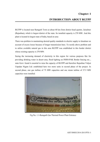
- 1. Chapter: 1 INTRODUCTION ABOUT RGTPP RGTPP is located near Ramgarh Town at about 60 km from district head quarter, Jaisalmer (Rajasthan), which is largest district of the state. Its installed capacity is 270 MW. And this plant is located in largest state of India, based on area There was problem in maintaining desired quality standards in electric supply to Jaisalmer on account of excess losses because of longer transmission lines. To rectify above problem and to utilize available natural gas in this area RGTPP was established in this border district whose existing capacity is 270 MW. Seeing the increasing demand of electricity in this region for various purposes like for providing drinking water in desert area, flood lighting on INDO-PAK Border fencing etc.., state Govt. found it essential to raise the capacity of RGTPP and therefore Rajasthan Vidyut Utpadan Nigam Ltd. established here two more units in second phase of the project. In second phase, one gas turbine of 75 MW capacities and one steam turbine of 37.5 MW capacities were installed. Fig No. 1.1-Ramgarh Gas Thermal Power Plant Entrance AIET/DOEE/2014-2015/PTS /1
- 2. Figure 1.2: Power Plant View 1.1 First Unit Necessary equipments for this power plant were supplied by Bharat Heavy Electrical Ltd. (BHEL), and building construction was carried out by Rajasthan State Bridge Construction Corporation. This unit is capable to generate power using both gas and diesel. In power plant 12 underground tanks are constructed for storage of diesel having total capacity of 2520KLt. In This Stage Gas Turbine (GT-1) Is Used Which Includes Unit Of 75 MW and steam turbine(ST-1) is used which include unit of 37.5 MW. 1.2 Second Unit First unit of this power plant is being operated by open cycle system, resulting in higher cost on electricity generation. Reduction in cost is only possible when first unit is operated on Combined Cycle System. So, under expansion program of this project, work AIET/DOEE/2014-2015/PTS /2
- 3. of installation of a gas ne and steam turbine is taken in hand. In this system, electricity will be generated by a steam turbine utilizing heat obtained from exhaust of gas turbines through a Heat Recovery Boiler. Thus, no additional fuel will be required for operating Steam Turbine. Under stage-II, one Gas Turbine Unit (110 MW) was commissioned and synchronized with the grid on june 2010 The Steam Turbine Unit (50 MW) was also commissioned and synchronized with the grid on june 2010 and thus the plant has been made operational in combined cycle mode with a total capacity of 270 MW. 1.3 Availability Of Water Requirement of water for power plant is supplied through Sagar Mal Gopa branch of Indira Gandhi Nahar Project. (IGNP). FOR THIS A 27 KM Long , 5.4 cusec capacity pipe line is laid from RD-190 of Sagar Mal Gopa Branch to power plant & another pipe line from RD- 200. For ensuring proper electric supply requirements, a Sub-station of capacity 2X250KVA, 33/0.4KV, and a pumping station has been established at RD-190 in addition to construction of a water storage tank of capacity 77000m3 at power plant. 1.4 Electricity Transmission System To ensure efficient transmission of electricity generated in the power plant, a 215km long Ramgarh-Jaisalmer-Barmer line & 165km Ramgarh-Pokaran of 132 KV has been laid. 1.5 Expected System Operation In spite of unfavorable geographical conditions and supply of gas of lower quality than expectation, expected electricity is being generated in this power plant. The details of total energy generated from this power station during years are as under AIET/DOEE/2014-2015/PTS /3
- 4. YEARS ENERGY GENERATED(MU) 1999-00 228 2000-01s 229 2001-02 120 2002-03 221 2003-04 238 2004-05 361.13 2005-06 435.62 2006-07 404.14 2007-08 414.11 2008-09 348.67 2009-10 424.11 2010-11 430.15 2011-12 431.98 Table no.1.1: Total Energy Generated 1.6 Gas Transportation System ONGC and IOCL are engaged in exploration of oil and natural gas deposits in western Rajasthan. Gas Authority Of India Ltd. (GAIL) laid down 12”diameter and 35 km long pipe line for supply of gas from Gamnewala based gas collection plant to Ramgarh, which has been further extended upto Dandewala gas field of Oil India Ltd. Total distance of Dandewala Terminal, is approximately 67 km from Ramgarh Terminal. This pipe line is being maintained by GAIL. Gas, which is use in plant, is mixture of different gas. Percentage of gas is as follws AIET/DOEE/2014-2015/PTS /4
- 5. Table no.1.2: Gas (full) Component AIET/DOEE/2014-2015/PTS /5 GAS PERCENTAGE NITROGEN 31.9064 % METHANE 48.5668 % CARBON DIOXIDE 18.8793 % ETHAN 0.5009 % PROPANE 0.0333 % ISO-BUTANE 0.0285 % N-BUTANE 0.0513 % ISO-PENANE 0.0185 % N-PENANE 0.0130 % HEXANE 0.0000 % TOTAL 100 %
- 6. Chapter: 2 POWER PLANT CYCLE Ramgarh Gas thermal power station is Combined Cycle power station. 2.1 Open Cycle When Gas Turbine (GT) exhaust is diverted directly into the atmosphere due to no provision of HRSG (Heat Recovery Steam Generator) or non availability of HRSG then it is called as GT is running in open cycle. In open cycle as gas turbine high exhaust gas is not utilized for heat transfer in boiler so its efficiency will come down. 2.2 Combined Cycle When Gas Turbine exhaust is diverted to HRSG in which high temperature Gas Turbine exhaust gas passes through HP Super Heater, HP Evaporator, HP Economizer, LP Evaporator, LP Economizer, and Condenser Preheated (CPH) thus heat of gas turbine exhaust gas absorbed by above series of bank located inside the HRSG and temperature of gas turbine exhaust which is about 570 deg C will come down to 135 deg C. By utilizing the heat of gas turbine exhaust HRSG (Boiler) generates Steam which is used to run Steam Turbine Generator (STG). AIET/DOEE/2014-2015/PTS /6
- 7. Thus we can generate an additional power (about 50 % of the gas turbine generation) in Steam Turbine Generator without any extra fuel cost. Thus we can get 30% extra efficiency by running the gas turbine in combined cycle. As gas turbine is operated on Brayton Cycle principle and Steam Turbine is rotated on Rankine cycle principle that is why it is called Combined Cycle. 2.3 Advantages of Combined Cycle Process Decreases in capital cost per mw installed. High overall efficiency i.e. 48%. Compact in size. Low main power required for its operation and maintenance. Low water requirement. Pollution free atmosphere and clean works place. Low installation time. High reliability and flexibility of the plant. 2.4 Brayton Cycle AIET/DOEE/2014-2015/PTS /7 FUEL COMBUSTION CHAMBER GENERATORCOMPRESSOR TURBINE
- 8. Figure 2.1: Brayton Cycle 2.5 Rankine Cycle AIET/DOEE/2014-2015/PTS /8 TURBINE EXHAUSTAIR STEAM GAS TURBINE EXHAUST TURBINEBOILER
- 9. Fig no 2.2: Rankine Cycle Chapter:3 BRIEF INTRODUCTION OF PLANT OPERATION At RGTPP gas to the turbines is being supplied through GAIL terminal from oil wells of ONGC and OIL, which are attached to discover oil and natural gas recourses in Western Rajasthan. The quantity of the gas is 9.5 Lac SCM per day. From GAIL Terminal gas is supplied to Gas Booster Compressor (GBC motor) at pressure of 10-15kg/cm2 and quantity of gas is 9.5 Lac SCM/day. The work of the Gas Boost Compressor is to compress gas and to supply required pressure of gas for power production to gas turbine. In compressing process by GBC the pressure of the gas increases from 10-15kg/cm2 to 18-23kg/cm2. The output of the GBC motor is first merged and then is divided further, before blowing into the Combustion Chamber. There are two GBC motor in RGTPS, GT-1 and GT-2. The blowing pressure is 18-23 kg/cm2 . Combustion Chamber is a place where ignition of fuel mixed with air occurs with the help of the sparkplugs, the voltage on both of the sparkplugs is 15000 V dc. On combustion, the gas gets mixed with air then the gas will expand and air pressure will increases. This air exhausts on the gas turbine buckets & nozzles and gas turbine starts to rotate. There are two generators AIET/DOEE/2014-2015/PTS /9 FEEDWATER CONDENSATE
- 10. of 35.5 MW and 37.5 MW attached with GT-1 and GT-2 respectively, mounted on the same shaft as the turbine. So GT-1 and GT-2 produces 35.5 and 37.5 MW electricity respectively. The exhaust of GT is flue gases. The temperature of flue gas is near about 500 deg C. This exhaust may also be relieved into the atmosphere with the help of controlled valves. But this exhaust is taken in use to produce electricity. So this power plant is called Combined Cycle Power plant. This exhaust (flue gas) of the gas turbine is further passed into the Heat Recovery Steam Generator (HRSG). It is a boiler. Water circulating in drum is superheated with the help of flue gases. This superheated steam runs the Steam Turbine Generator, so it is called unfired combined cycle. The generator is mounted on the same shaft as of the steam turbine, produces 37.5 MW electricity. The steam which is blowing on the gas turbine should be superheated. Steam should be superheated so that- 1. No corrosion will be occur, 2. Enthalpy drop will be less. Power generation is also done at low voltage because of the insulation problem. If the power generation is done at high voltage then there are following disadvantages- 1. Losses will be more 2. Wire also may burn out 3. High insulation will be required which is very costly AIET/DOEE/2014-2015/PTS /10
- 11. Figure: 3.1 Operation of RGTPP AIET/DOEE/2014-2015/PTS /11
- 12. Chapter: 4 GAS TURBINE Turbine Equipments 4.1 Compressor The atmosphere air is compressed to the 17 stage compressor and before it passes through the filter. The compressor ratio is 10 and this air is routed to the combustors. The compressor used in the plant is of rotatory type. The air at atmospheric pressure is drawn by the compressor via the filter which removes the dust from the air. There are 396 no. of filters connected in different rows. These filters are made up of cellulose fiber. The rotatory blades of the compressor push the air between stationary blades to raise its pressure 4.2Combustors The fuel (gas) is provided to ten equal flow lines, each terminating at a fuel nozzle centered in the end plate of a ten separate combustion chamber and prior to being distributed to the nozzles, the fuel is actually controlled at a rate consistent with the speed and load requirements of gas turbine. The nozzle introduces the fuel into the combustion chambers where it mixes with the combustion air and is ignited by the sparkplugs. At instant when fuel is ignited in one combustion chamber, flame is propagated through connecting crossfire tubes to all other combustion chambers. 4.3 Transition Pieces The hot gases from the combustion chambers expand into the ten separate transition pieces and from there to the three stage turbine section of the machine 4.4 Turbine There are three stages of the turbine and each consists of a row of fixed nozzles followed by a row of rotating turbine buckets. In each nozzle row, the kinetic energy of the jet is increased with AIET/DOEE/2014-2015/PTS /12
- 13. an associated pressure drop and in each following row of a moving buckets, a portion of the kinetic energy of the jet is absorbed as useful work on the turbine rotor. 4.5 Exhaust After passing through the third stage buckets, the gases are directed into the exhaust hood diffuser which contains a series of turning vanes to turn the gases from an axial direction to a radial direction, thereby minimizing exhaust hood losses. The gases then pass into the exhaust plenum and are introduced to atmosphere through the exhaust stack or to the H.R.S.G. AIET/DOEE/2014-2015/PTS /13
- 14. Chapter: 5 GAS TURBINE SUPPORT SYSTEM AND THEIR EQUIPMENTS 5.1 Starting System 5.1.1 Diesel Engine Diesel engine/starting motor/Main generator with static frequency converter. Diesel or starting motor with torque converter or main generator with SFC is used as a starting device for gas turbine. We have Detroit make diesel engine of 590 hp for starting purpose. 5.1.2 Torque Converter It transfers torque from DG to Gas Turbine. It is a hydraulic coupling which transfers torque from zero speed to self sustaining speed of Gas Turbine (i.e. about 60% speeds). 5.1.3 Accessory Gear Box It accommodates following equipments ----Main lube. Oil pump ----Main hydraulic pump ----Main fuel oil pump ----Atomizing air compressor 5.1.4 Hydraulic Ratchet It rotates the turbine shaft when gas turbine is on cool down. It also helps while break away of Gas Turbine during starting. It consists of a ratchet mechanism operated by hydraulic device. Oil is supplied by a DC driven positive displacement pump. AIET/DOEE/2014-2015/PTS /14
- 15. 5.1.5 Jaw Clutch Mechanism It transmits power from Diesel Engine or Ratchet Mechanism to Gas Turbine through Torque Converter for starting of Gas turbine or at the time of ratcheting. 5.2 Lubricating Oil System Major equipment of the system are- 5.2.1 Oil Reservoir: The capacity is 3300 gallons. The total system requirement is 3500 gallons. Lubricating Pump: Main lube oil pump is accessory gear driven. Also for starting a/c power driven lube oil pump of 175m head and 460gpm flow is provided. For emergency purpose DC pump of 91m head and 250 gpm flow is provided. During emergency pump in service filter remain by pass. 5.2.2 Heat Exchanger: Two coolers are provided for cooling oil each of 100% capacity. 5.2.3 Gas Skid: The function of the gas conditioning skid is to supply gas to Gas Turbine free from condensate and gas particles. 5.2.4 Scrubber: The function of the scrubber is to remove condensate from gas by centrifugal action by the use of no. parting plates within the scrubber itself. There is a provision of solenoid operated drain valve for removal of condensate which is sensed by a level switch. 5.2.5 Filter: The function of filter is to remove any foreign particles from the gas and to supply totally clean gas. This filters are of cartridge type and replaceable if d.p across the filter increases. AIET/DOEE/2014-2015/PTS /15
- 16. 5.2.6 Pressure Control Valve: The function of the pressure control valve is to regulate down steam pressure up to 22kg/cm2 if upstream pressure is more. This is the designed value for inlet the gas stop ratio control valve. 5.2.8 Condensate Tank: All the condensate collected at the bottom of the scrubber is routed to the tank through drain piping. For this is a level controller on the scrubber which will operate on maximum and minimum level scrubber. 5.3Air Intake System: 5.3.1 Filters: There are 396 no. of filters connected in different rows. These filters are made up of cellulose fiber. Fig No. 5.1-Filter AIET/DOEE/2014-2015/PTS /16
- 17. 5.3.2 Filter Cleaning: Reverse pulse self cleaning system is provided for cleaning of these fibers. Processor air is used for these pulsations. Each row is given reverse pulse at fixed time interval and in predefined rotation. 5.3.3 Air Processing Unit: The air from the compressor output is taken to finned tube to cool it and is passed through the dryer for removing moistur 5.4 Cooling and Sealing Air System: Air for the bearing sealing is extracted from the 5th stage of the compressor. Centrifugal removes dust and other foreign particles. Two centrifugal blowers are provided for turbine shell cooling 5.4.1 Ventilating System: Being a closed system, air circulation is provided by following ventilating fans in different compartments: 1. Accessory and gas turbine compartment vent fan-2 no. 2. Load gear compartment -2 no. 3. Gas valve compartment vent fan -1 no. 4. Load gear oil vapors fan-1 no. 5.4.2 Gas Turbine and Compressor Cleaning System: Compressor washing skid consists of: a) Water tank with heaters, b) Water pump, c) Detergent pump, d) Water wash valve (electrically operated). Rice hopper is provided at compressor suction for solid compound cleaning of compressor. AIET/DOEE/2014-2015/PTS /17
- 18. 5.4.3 Reducing Gear Box:- Gas turbine speed is 5100rpm, but generator speed is designed as 3000rpm, so reducing gear box is provided to reduce speed to 3000 rpm. 5.5 H.R.S.G And Steam Turbine Equipment:- 5.5.1 H.R.S.G: HRSG is a horizontal, natural circulation, bid rum, dual pressure unfired water tube boiler. It is designed to generate HP steam at 62kg/cm2 pressure and 483 deg C temperature with 59.9 t/hr steam flow. LP steam is generated at 5 kg/cm2 pressure and at saturated temperature with 10.9t/hr steam flow. These H.R.S.Gs are having facilities of HP and LP bypass systems 100% for both the circuits to match the rated parameters(pressure and temperature) while starting the H.R.S.Gs and to minimize the losses of water and heat while shutting down the m/c. These are also useful when STG trips and to keep boiler in service. Major equipments of recovery boilers are: 1) Super heater, 2) Evaporator (HP & LP), 3) Economizer (HP-1, 2 & LP) 4) Stack (height) 5.5.2 Steam Turbine: The HP Steam Turbine is drawn from HP steam header of H.R.S.G 1&2. The HP steam parameters of the HP steam are 60kg/cm2 pressure and 480deg C temperature. The LP steam to turbine is drawn from LP steam header of HRSG 1&2. The LP steam parameters of LP steam are 4.3kg/cm2 pressure and 148 deg C temperature. 5.6 Condensate Circuit Equipment: It consists of condensers, ejectors, extraction pumps, gland steam condenser. AIET/DOEE/2014-2015/PTS /18
- 19. 5.6.1 Condenser: It is a two pass condenser having 9084 no. of tubes having cooling surface area of 3070m2 . It has steam condensing capacity of 137t/hr, cooling water flow of 7050m3 /hr. 5.6.2 Ejectors: Two no. of two pass ejectors are provided each having a capacity of handiling15kg/hr dry air 49kg/hr air-water vapor mixture. One starting ejector is also there of 220kg/hr of dry air handling capacity at a suction pressure of 0.33 atmosphere. 5.6.3 Extraction pumps: Two no. of pumps each of 100% capacity are used in the system. Each has a capacity of 95 m head and 186m3 /hr flow. 5.6.4 Gland Steam Condenser: Steam leaking from turbine glands is used to raise the temperature of the condensate by GSC. Two no. of fans are provided for extracting steam. .7 Feed Water Circuit It consists of the feed water tank; HP & LP feed water pumps. 5.7.1 Feed Water Tank: It is mounted at elevation of 9m so it provides a net positive suction head to the boilers feed pumps. It also has a deaerator at the top of the tank for mechanical dearation of the feed water. 5.7.2 HP Feed Pumps: Three feed pumps of 50% duty are provided to feed h.p water to boiler. Each is a KSB make, multistage pump with discharge head of 925m and 75m3 /hr. 5.7.3 LP Feed Pumps Three feed pumps of 50% duty are provided to feed l.p water to the boiler. Each is a Beacon Water make, multistage pump with discharge head of 117m and 11.5m3 /hr. AIET/DOEE/2014-2015/PTS /19
- 20. 5.8 Common Support System For GT And ST:- 5.8.1 CW and ACW systems: There are three CW pumps each of 50% capacity of 23 head and 3850t/hr flow. They circulate water in steam turbine condenser and ST oil cooler. There are three ACW pumps each of 50% capacity of 34m head and 576t/hr flow. They circulate water in following gas turbine auxiliaries: A) Diesel engine, B) Lub. Oil coolers, C) Generator air coolers. It also circulates in feed pump bearing, coolers of AC plant, air compressors, ADUs and boilers water sample coolers 5.8.2 Air Compressors: Air is required for the following purposes: a) For pneumatic operations of all control valves, b) At different maintenance work places for cleaning, c) If required it can be used for GT filter cleaning. There are three kirlosker make horizontal, balanced opposed piston compressor each of 8.1kg/cm2 head and 253 Nm cu. /hr air flow. Air from the receiver tank is directed to air drying unit to moister free. 5.8.3 Raw Water System: Three no. of bore wells supply raw water to a water reservoir from which is transferred to water treatment plant by use of raw water pumps each of 125t/hr flow capacity. Each bore well is of @ 125 to 150t/hr flow capacity. Daily raw water consumption of the plant is around 4000t. 5.8.4 Laboratory: Any power plant requires soft water and dematerialized water in large quantity. There are soft water plant (cap 7.2 t/hr*2) which is used in the boiler water circuit. Apart from that, a AIET/DOEE/2014-2015/PTS /20
- 21. continuous watch is kept of water chemistry of HRSG water to keep its parameters (such as ph and conductivity) within a specified range. 5.8.5 Fire Protection Systems: It includes no. of water pumps, halon & CO2 bank, nozzle and piping net work, flame and smoke detectors and emulsifies. There are three types of water pumps: a) HVWS pump, b) Jockey pump. 5.8.6 Black Start D.G Set: In the event of total power failure, GT can be started with the help of diesel generating set (500 KVA, 680 Amp. Max) which is capable of supplying power to the bare minimum requirements of the auxiliaries of one gas turbine. Later, other auxiliaries can be started with the help of running gas turbine AIET/DOEE/2014-2015/PTS /21
- 22. Chapter: 6 CONSTRUCTIONAL DETAILS OF GAS TURBINE 6.1 Compressor Section The axial-flow compressor consists of the compressor rotor and the enclosing casing. The inlet guide vanes, the seventeen stages of the rotor and stator balding and the two exit guide vanes are included with in the compressor casing. In the compressor, air is confined to the space between the rotor and stator balding where it is compressed in stages by a series of alternate rotating (rotor) and stationary (stator) aerofoil -shaped blades. The rotor blades supply the force needed to compress the air in each stage and the stator blades guide the air so that it enters the following rotor stage at the proper angle .The compressed air exits through the compressor discharge casing to the combustion chambers. Air is exerted from the compressor for turbine cooling bearing sealing and, during start-up, for pulsation control. 6.1.1 Rotor: The compressor rotor is an assembly of fifteen wheels two stub shaft, through bolts, and the compressor rotor bulkhead .The first stage rotor blades are mounted on the wheel portion of the forward stub shaft. 6.1.2 Stator: The stator (casing) area of the compressor section is composed of five major sections: (1) Inlet Casing (2) Inlet Guide Vanes (3) Forward Compressor Casing (4) Aft Compressor Casing (5) Compressor Discharge Casing AIET/DOEE/2014-2015/PTS /22
- 23. 6.2 Combustion Section: The combustion system is the reverse flow type and comprises ten combustion chambers with liners, flow sleeves, transition pieces and crossfire tubes. Flame detectors, crossfire tubes, fuel nozzles and spark plug igniters are also part of the complete system. Hot gases, generated from the burning of fuel in the combustion chambers, are used to drive the turbine. 6.2.1 Combustion Chambers: Discharge air from the axial-flow compressor enters the combustion chambers from the cavity at the center of the unit. The air flows upstream along the outside of the combustion liner towards the 1 inner cap . This air enters the combustion chamber reaction zone through the fuel nozzle swirl tip(when fitted) and through metering holes in both the cap and liner .When the nozzles supplied are not of the type fitted with a swirl tip, the combustion chambers are fitted with a tabulator system. The hot combustion gases from the reaction zone pass through a thermal soaking zone and then into a dilution zone where additional air is mixed with a combustion gases. Metering holes in the dilution zone allows the correct amount of air to enter and cool the gases to the required temperature. Openings located along the length of the combustion liner and in the liner cap provide a film of air for cooling the walls on the liner and cap. Transition pieces direct the hot gases from the liners to the turbine nozzles. The ten combustion chamber casings are identical with the exception of those fitted with spark plugs or flame detectors. 6.2.2 Spark Plugs: Combustion is initiated by means of high-voltage, retractable -electrode spark plugs installed in two of the combustion chambers. This spring -injected and pressure -retracted plugs receive their energy from ignition transformers. At the time of firing, a spark at one or both of these plugs ignites the combustion gases in a chamber. The gases in the remaining chambers are ignited by crossfire through the tubes that interconnect the reaction zones of the remaining chambers. As AIET/DOEE/2014-2015/PTS /23
- 24. rotor speed increases, chamber pressure causes the spark plugs to retract and the electrodes are removed from the combustion zone. GAS PRESSURE ( kg/cm2 ) 22 kg/cm2 HYDRAULIC OIL PRESSURE ( kg/cm2 ) 80 kg/cm2 GENERATOR BEARING PRESSURE ( kg/cm2 ) 0.5 kg/cm2 RATIO VALVE GAS PRESSURE ( kg/cm2 ) 16 kg/cm2 LUBE OIL PRESSURE ( kg/cm2 ) 2 kg/cm2 GAS TEMPERATURE (deg C ) 120 deg C LUBE OIL TANK TEMPERATURE (deg C ) 50-60 deg C GENERATOR rpm 3000 GENERATOR TURBINE rpm 5000 GENERATING VOLTAGE( kilo volt ) 11KV TURBINE MW 35.5 MW Table No.- 6.1 : Gas Turbine-1 (GT-1) GAS PRESSURE ( kg/cm2 ) 22 kg/cm2 HYDRAULIC OIL PRESSURE ( kg/cm2 ) 80 kg/cm2 GENERATOR BEARING PRESSURE ( kg/cm2 ) 0.5 kg/cm2 RATIO VALVE GAS PRESSURE ( kg/cm2 ) 16 kg/cm2 AIET/DOEE/2014-2015/PTS /24
- 25. LUBE OIL PRESSURE ( kg/cm2 ) 2 kg/cm2 GAS TEMPERATURE (deg C ) 120 deg C LUBE OIL TANK TEMPERATURE (deg C ) 50-60 deg C GENERATOR rpm 3000 GENERATOR TURBINE rpm 5000 GENERATING VOLTAGE ( kilo volt) 11KV TURBINE MW 37.5 MW Table No. 6.2 : Gas Turbine-2 (GT-2) 6.3 STG (Steam Turbine Generator) INTRODUCTION: Steam turbo generator in RGTPP is the capacity of 87.5 MW and STG runs in combined cycle mode utilizing heat of GT-1 and GT-2. In such combined power plant higher thermal efficiency as compare to coal thermal power plant. 6.3.1 Turbine: The function of the turbine is to drive the generator at a speed of 3000 rpm. The heat energy of steam (enthalpy) is converted in mechanical energy as steam expands in turbine. Before entering the main steam in turbine it passes through emergency stop valve and control valve located at turbine floor, there are 53 stages in turbine, one stage consists of a set of fixed blade mounted on inner casing and rotary blade mounted on turbine shaft. LP injection is connected after 43 stages of turbine. The turbine shaft is supported by the front bearing (Journal & thrust bearing) and the rear bearing (Journal bearing) .The axial thrust produced in the moving blades is balanced by balancing drum located in the front side of turbine. The residual thrust forces of turbine that have not been compensated by balancing piston are taken up by the front thrust bearing .The rear bearing of turbine houses the oil hydraulic turning device used for running the turbine on bearing gear. Turbine gland sealing is done to avoid air entry initially at both gland ends at in running to AIET/DOEE/2014-2015/PTS /25
- 26. seal the LP end gland. When turbine is running sealing is done through turbine leak steam itself and balance steam flows to condenser. 6.3-1-1 Turbine Oil System: a)Main Oil Tank (MOT): MOT is located on 5m. It serves for storing the oil volume required for governing and Lubrication system .Oil vapor in oil tank are vented out by an oil vapor exhaust fan installed at the top of MOT. The MOT is provided with oil centrifuge inlet connection at bottom and the oil centrifuge return is connected back to oil tank. The oil centrifuge cleans the oil stored in MOT. b)MOP: Lubrication oil needed for turbine bearing, governing oil system and barring gear is supplied by MOPs .The bearing Lubrication oil is supplied after cooler and duplex filter but governing oil and barring gear oil flows directly from the MOP discharge header. Discharge Pressure -- 10.2kg/cm2 Flow -- 150 m3 /hr Motor rating --55 KW, 93 A Standby pump comes in service at header pr below --6.5 Kg/cm2 c) DC EOP: In case of tripping /non availability of both MOPS ,DCEOP server for supplying oil for bearing cooling .The emergency oil pump cuts in automatically when oil header pr falls below 0.9 Kg/cm2 in the event of further pressure fall in header, Oil shall be fed from an overhead oil tank placed about 6.5 m over the turbine. (d) Jacking Oil Pump (JOP): In the case of start up and shut down, on barring gear it is necessary to supply the high oil pr to lift the shafting system slightly so as to avoid metal to metal contact. Friction between shaft and bearing .For this purpose two nos. JOPS are provided; one is AC-JOP and another is DC-JOP. AIET/DOEE/2014-2015/PTS /26
- 27. Fig.No.6.1-Oil Cooling System 6.4 Heat Recovery Steam Generator (HRSG): Two no. of HRSG Established; one each for steam generation utilizing waste heat of exhaust gases of GT1 GT2 respectively .HSRG is natural circulation Unfired Steam Generator Feed water coming from BFP discharge passes through the tube bunches of different modules of heat transfer surfaces and gets heated by gas turbine exhaust flowing in surrounding duct. HRSG has nine heat transfer surfaces as mentioned below: (i) High Pressure Super Heater (ii) HP-evaporator including HP drum (iii) HP-Economizer for preheating the feed water entering in drum. These are three in nos. (iv) LP- Super Heater (v) LP- Evaporator including LP drum (vi) LP- Economizer (vii) Condensate preheated (CPH) for heating condensate water before flowing to Deaerator. AIET/DOEE/2014-2015/PTS /27
- 28. Fig No.6.2-Power Plant View HPBFP-1,2,3 425 Kw 3 LPBFP-1,2,3 22 Kw 3 HP DOSING PUMP(HP CIRCUIT) 0.75Kw 4 LP DOSING PUMP(LP CIRCUIT) 0.37Kw 4 DEARATOR 1 Table No. 6.3: HRSG -1 & 2 AIET/DOEE/2014-2015/PTS /28
- 29. Fig No.6.3 -Water Tube Boiler Fig.No. 6.4-H.R.S.G Gas Cycle In HRSG: HP Super Heater -- HP Evaporator -- HP Eco III -- LPSH --LP Evaporator -- HP Eco II -- LP Eco -- HP Eco I – CPH -- Chimney 6.5 Generator AIET/DOEE/2014-2015/PTS /29
- 30. The gas turbine is coupled with the generator. The alternator converts the mechanical energy of the turbine into electrical energy. The output of the alternator is given to the bus-bars through transformers, isolators and circuit breakers. MW -- 40.8 Pf -- 0.80 MVA -- 51 Stator volt – 11kV Stator current -- 2677A Rotor volt -- 246V Rotor amp -- 717A 6.6 Water & Steam Cycle Equipment: 6.6.1 Water & Steam Cycle: Dearator -- HP BFP --Feed water control station --HP Eco -- HP drum –HP SH--Turbine (HP Steam) --Condenser --CEP--Ejector --GSC--CPH --Dearator control valve station --dearator. For LP MS another cycle sub-path through LP BFP is maintained: Dearator --LP BFP --LP Eco --LP drum --LP SH -Turbine (LP Injection Steam) 6.6.1-1 Deaerator (Physical Location- Between HRSG 1 & HRSG 2): It is in two parts; one is Dearating column where Dearation takes place in spray valve cum tray chamber and another is feed water storage tank which is used as water reservoir tank with capacity of 27.5 m3 .Whole assembly is known as Dearator. Steam pegging is also done in Dearator to increase Dearation, feed water temp and BFP suction pressure .Condensate discharge through CPH (condensate preheater comes here in a chamber with 12 spray valve and 9 tray s AIET/DOEE/2014-2015/PTS /30
- 31. and Dearation takes place. Air comes out of the air vent vent and water flows down in reservoir feed water Storage tank. Dearator level: Normal: 0 mm Low (alarm) :(-) 400 mm Very low (tripping of BFP) : (-) 1500 mm 6.6-1-2 HP BFP (Physical location: below Dearator and between HRSG 1 & HRSG 2) - High pressure Boiler feed pumps are three in nos. and two are continuously running for full load operation. HP BFP cooling: – (i) oil cooling for bearing and oil level around 1/2 of the pot size in maintained in oil pot (ii) Seal water cooler for cooling DM water, which is used for sealing the gland. The flushing DM water is further cooled in seal water cooler by ACW water. (iii) ACW cooling for bearing oil chamber. Permissive for starting HP BFP -- (i) Suction valve open (ii) Ready to start -i.e. switchgear remote clearance signal is ok (iii) deaerator level ok-above (iv) Pump bearing temp normal -below 80 deg (v) Motor bearing temp normal -below 80 deg (vi) Motor winding temp normal -below 80 deg. One recirculation line tapped from discharge line is connected to deaerator to facilitate minimum discharge flow while BFP is running .The balance leak off line taped from impeller intermediate stage is also connected to deaerator to balance thrust. The manual valves of these lines located at AIET/DOEE/2014-2015/PTS /31
- 32. deaerator floor should be kept open at the time of starting BFP. Manual suction valve and motorized discharge valve are located at the floor just above BFP. All the three discharge valves are opened while starting first BFP on auto. 6.6-1-3 LP BFP (Physical location: below deaerator and between HRSG 1 & HRSG2): LP BFPS are similar in constructions and operation as HP BFP mentioned above but with very low capacity as compared to the HP BFP. LP BFP cooling – (i) Oil cooling for bearing and oil level around1/2 of the post size is maintained in oil pot. (ii) Seal water cooler for cooling the DM water which is used for sealing the gland .The flushing DM water is further cooled in seal water cooler by ACW water. (iii) ACW cooling for bearing oil chamber. LP BFP tripping --- (i) Discharge pressure --14kg/cm2 (ii) deaerator level is very low-(-)1500mm Permissive for starting LP BFP -- 1>Suction valve open 2> Ready to start -i.e. switchgear remote clearance signal is ok 3>deaerator level not low i.e. above(-) 400 mm 6.6-1-4 Condenser – Turbine exhaust is connected to condenser. Condenser here used is surface condenser. Circulating water pump discharge water flows through condenser tubes &cools steam in surrounding areas coming out of turbine. Hot well is bottom part of condenser where condensate resulting from condensation of steam is collected and we can add make up water here to compensate line losses of closed water cycle. AIET/DOEE/2014-2015/PTS /32
- 33. Condenser pressure -- (-) 0.9 kg/cm2 Low -- very low Hotwell level ---0 mm (normal) Condenser cooling water temp. --33.0 deg 6.6-1-5 Condenser Extraction Pump (Physical location at (-) 1m level): Condensate Extraction pump ( CEP) are three in nos. and out of them two pumps run for full load operation .These vertical pumps are used to facilitate pumping the condensate back to deaerator . Discharge pressure ----14.8 kg/cm2 Flow----107 m3/ hr Full load current ----123 A Motor rating ----75 Kw 6.6-1-6 Ejector (Physical location: 5m) – Ejectors are used to create vacuum in condenser. Starting ejector is charged initially to create fast vacuum. Starting Ejector basically consist of a nozzle through which pressure energy of incoming aux steam is converted in kinetic energy and passing through high velocity it entails air from condenser and the exhausted air and steam mixture flows to the atmosphere .Whereas in main ejector aux steam accelerating through nozzle is also being utilized in heating CEP discharge condensate and the condensed steam flows to condenser through manual valves instead of being exhausted to atmosphere as in case of starting ejector. 6.6-1-7 Gland Steam Cooler (GSC) (Physical location: 5m)- AIET/DOEE/2014-2015/PTS /33
- 34. Here condensate flows in GSC tubes and heated gland steam coming out of the turbine gland sealing. 6.6-1-8 Condensate Preheater (CPH) (Physical location: HRSG drum floor): CPH is located as a last heat transfer surface in exhaust gas path before flowing to 70m high stack. Condensate water flowing in CPH tubes heated through exhaust gas. CPH inlet water temp ----48 deg CPH outlet water temp---94.7 deg 6.7 HP Bypass & LP Bypass (HPBP& LPBP): HPBP and LPBP are used to bypass the turbine rolling parameter is achieved. HPBP line is tapped off from individual HRSG MS line and valves are located at 5 m in front of condenser. Similarly LPBP line is tapped off from individual HRSG (LP system) and one valve is located in the front of condenser at 5m and another is behind the condenser at separate platform. HPBP & LPBP dumps MS directly to condenser after reducing pressure .Downstream temp are reduced in case of HPBP by spraying BFP discharge water. HPBP /LPBP control valves flows on following protections: HPBP /LPBP solenoid valve open on protection. (i) Generator circuit breaker open (ii) Turbine tripped 6.8 Auxiliaries: (i) Circulating Water Pump (CW Pump): These are three in nos. and located in pump house .These pumps are used for circulating water through condenser tubes so as to condense the turbine exhaust steam Discharge pr---2.5kg/cm2 Flow--- 4500 m3/hr Full load current ---43 A AIET/DOEE/2014-2015/PTS /34
- 35. Motor rating ---400kW, 6.6kV (ii) Auxiliary Cooling Water Pump (ACW Pump): These are two in nos. and also located in pump house. These pumps are used for following purpose: (a) BFG bearing and seal water cooling (b) Generator air cooling (c) Compressor lubes oil cooling (d) Turbine bearing oil cooling (e) In GT area for gas booster compressor and atomizing air cooler ACW pumps along with CW pumps take suction from pump located underground beneath them and return is cooled by cooling towers. Discharge pressure ---4.5 kg/cm2 Flow ---655 m3 /hr Full load current ---215 A Motor rating ---125 kW, 415v Chapter: 7 CONSTRUCTION DETAILS OF GENERATOR AND EXCITER Generator: The generator is two pole, cylindrical rotor, air cooled type-TARI, Siemens,Designs of BHEL make. Main components of generator are – 7.1 Stator 7.1.1 Stator frame 7.1.2 Stator core AIET/DOEE/2014-2015/PTS /35
- 36. 7.1.3 Stator windings 7.1.4 Stator and covers 7.2 Rotor 7.2.1 Rotor Shaft 7.2.2 Rotor winding and retaining ring 7.2.3 Field connections 7.3 Bearings 7.4 Generator and Air Cooler 7.5 Excitation System 7.1 Stator: 7.1.1 Stator Frame: Stator frame supports the laminated core and stator winding. It is welded construction consisting of stator frame housing, two flanged rings, axial and radial ribs. The dimensions and arrangement of ribs is determined by cooling air passage and required material strength and stiffness. Ventilating air ducts are provided in the radial ribs. Footings are provided to support the stator frame on foundation plates by means of bolts. 7.1.2 Stator Core: Stator core is build from silicon steel electrical grade laminations. Each lamination is made up from number of individual segments. Segments are stacked on insulating bars which hold them in position. One bar is kept un- insulated to provide grounding of laminated core. The laminations are hydraulically compressed and located in frame by means of camping bolts and pressure plates. Clamping bolts run through the core and are made of non magnetic steel and are insulated from the core to prevent short circuiting of the core. Clamping fingers are provided at the ends which ensure compression in teeth area. The clamping fingers are made up of non magnetic steel to avoid eddy current losses. AIET/DOEE/2014-2015/PTS /36
- 37. 7.1.3 Stator Winding: Stator winding is two layers short pitch winding consisting of stator bars of rectangular cross section. Each bar consists of number of separately insulated strands. In slot portion the strands are transposed to ensure uniform distribution of current over entire cross section of the bar. The high voltage insulation is epoxy cast resin type bonded with mica. The insulation is continuous, void free, extremely low moisture absorbent, oil resistant and exhibits excellent electrical, mechanical and thermal properties. A coat of semi conducting varnish is applied over the surface of all bars within the sot range to minimize corona discharges between and slot wall. All the bars are additionally provided with end corona protection to control the field at that location and to prevent formation of creep age sparks. Several layers of semi conductive varnish are applied at varying lengths to ensure uniform electric field. A final wrapping of glass fabric tape impregnated with epoxy resin is provided which serves as surface protection. The stator bars are inserted in slots with very small clearances. At the top they are secured by slot wedges and ripple springs. In the end windings the bars are firmly lasted to supporting brackets. Spacer blockers are placed between the bars to take care of electromagnetic forces that may be produced during short-circuits. The beginning and the ends of the three phase winding are solidly bolted to output leads with flexible. Output leads are copper flats inserted into insulating sleeve. 7.1.4 Stator End Covers: Stator and covers are attached to the end flanges of stator frame and rest on a foundation frame. The end covers aluminum alloy castings. AIET/DOEE/2014-2015/PTS /37
- 38. Fig No.7.1-Steam Turbine Fig No.7.2- Bearing AIET/DOEE/2014-2015/PTS /38
- 39. Fig No.7.3- Steam Turbine Cover 7.2 Rotor: 7.2.1 Rotor Shaft: The rotor shaft is single piece solid forging. Slots for winding are miled into rotor body. Axial and radial holes are provided at the base of the rotor teeth forming air cooling ducts. 7.2.2 Rotor Winding: The rotor winding consists of several series connected coils which form north and south poles. The conductors have rectangular cross section and are provided with axial slots for radial discharge of hot air. Individual conductor is bend to obtain half turn. After insertion into slots these turns are brazed to form one full turn. Individual coils are series connected so that one north and one South Pole are obtained. Conductors are made of copper having 0.1% silver content to provide high strength at higher temperatures so that coil deformation due to thermal stresses is avoided. Individual turn of the coil is insulated with glass fiber tape. Glass fiber laminates are used slot insulation. To protect the winding against the effects of centrifugal forces the winding is secured in the slots with wedges. Slot wedges are made from alloy high strength and high electrical conductivity AIET/DOEE/2014-2015/PTS /39
- 40. material. This also acts as damper winding. At the ends, slot wedges are short circuited through the retaining ring which acts as short circuiting ring to induced currents in damper windings. Retaining rings of high strength of non magnet steel are provided. 7.2.3 Field Connections: The connections of the rotor windings are brought out at the exciter side shaft end through rotor shaft bore. 7.3 Bearings The rotor is supported in two sleeve bearings. To eliminate shaft currents the exciter end bearing is insulated from the foundation frame & oil piping. Temperatures of the bearing are monitored by two RTDs embedded in the lower half of the sleeve bearing. Bearings also have provision of fixing vibration pickups to monitor bearing vibrations transmitted from the shaft. HEADER PRESSURE ( kg/cm2 ) 8.8 kg/cm2 LUBE OIL TANK TEMPERATURE(deg C ) 50 deg C AIET/DOEE/2014-2015/PTS /40
- 41. AUXILARY STEAM PRESSURE 11.2 kg/cm2 AUXILARY STEAM TEMPERATURE (deg C ) 180 deg C CONDENSOR VACCUME VALUE ( kg/cm2 ) -0.92 kg/cm2 SEAL STEAM PRESSURE ( kg/cm2 ) 0.3 kg/cm2 SEAL STEAM TEMPERATURE (deg C ) 120 deg C CEP HEADER PRESSURE ( kg/cm2 ) 15 kg CEP MOTOR CURRENT ( amp ) 95 amp HPCV POSITION 0-100% LPCV POSITION 0-100% CONTROL OIL PRESSURE ( kg/cm2 ) 8 kg/cm2 TRIP OIL PRESSURE ( kg/cm2 ) 9 kg/cm2 BEARING OIL PRESSURE ( kg/cm2 ) 0.35 kg/cm2 BEARING OIL TEMPERATURE (deg C ) 55 deg C STEAM TURBINE rpm 3000 rpm GENERATOR rpm 3000 rpm GENERATING VOLTAGE ( kilo volt ) 11kv TURBINE MW 37.5 MW TYPE OF COOLING ONAN/ONAF RATING H.V (M.V.A) 40/50 RATING L.V (M.V.A) 40/50 NO LOAD VOLTAGE H.V (KV) 138 NO LOAD VOLTAGE L.V (KV) 11 LINE CURRENT H.V (AMPS.) 167.35 209.19 2099.46 2624.32LINE CURRENT L.V (AMPS.) TEMPERATURE RISE OIL (DEGREE C) 50 deg TEMPERATURE RISE WINDING (DEGREE C) 55 deg AIET/DOEE/2014-2015/PTS /41
- 42. PHASE 3 FREQUENCY (Hz) 50 CONNECTON SYMBOL YNd 11 MANUFACTURING UNIT JHANSI % GURANTED IMPEDENCE AT NORMAL TAP VOLTAGE % (HV-LV) 12.5 + ISTOL (AT 50 MVA BASED ) CORE AND WINDING (Kg) 35000 WEIGHT OF OIL (Kg) (INCLUDING 10% EXTRA) 21500 TOTAL WEIGHT INCLUDING OIL (Kg) 87000 OIL QUANTITY (LITRE) (INCLUDING 10% EXTRA ) 24000 TRANSPORT WEIGHT (Kg) (GAS FILLED) 45000 UNTANKING WEIGHT (Kg) 35000 Table No. 7.1: Steam Turbine Generator H.V 650 KVP/300 K.V.rms L.V 75 KVP/28 K.V.rms H.V.N 95 KVP/38 K.V.rms Table No. 7.2: Insulation Level 7.4. Air Cooling Circuits: The cooling air is circulated in the generator by two axial flow fans fixed at each end of the rotor shaft. Cold air is drawn by fans from cooler compartment located at the side of the generator. The cooling air directed into the rotor end winding and cools the windings. Some air flows in the rotor slots at bottom duct from where it is discharged into the air gap via radial ventilating slots in the coil and bores in the rotor wedges. AIET/DOEE/2014-2015/PTS /42
- 43. Part of the flow is directed over the stator overhang to the cold air duct and to the gap between the stator frame and stator core. Air then flows through ventilating ducts in the core into the air gap. The balanced air is directed into the air gap over the retaining rings cooling it. 7.5 Excitation System: The excitation system is of brushless type and consists of following- 1. three phase pilot exciter 2. three phase main exciter 3. rectified wheel The three phase pilot exciter is a permanent magnet type. Three phase output from the pilot exciter is fed into the AVR (Automatic Voltage Regulator).From the AVR regulated dc output is fed to the stationary field coils of main exciter. The three phase output from the rotating armature of the main exciter is fed to the rectifier wheel, from where it is fed to the field winding of the generator rotor through dc leads in the rotor shaft. 7.5.1 Pilot Exciter: Pilot exciter is six pole units. The stator is consists of laminated core and carries three phase winding. Rotor consists of hub on which six permanent magnets poles are mounted. 7.5.2 Main Exciter: Main exciter is six pole revolving armature types. Field winding and poles are mounted on stator. At the pole shoe the damper winding is provided. Between the two poles a quadrature axis coil is fitted for induced measurement of armature current or generator rotor current. 7.5.3 Rectifier Wheel: Main components of the rectifier wheels are silicon diodes arranged in three phase bridge configuration. Each diode is fixed in a heat sink. A fuse provided for each diode to switch off the AIET/DOEE/2014-2015/PTS /43
- 44. diode when it fails. These fuses in the diodes can be checked while generator is running, with the help of stroboscope. Chapter : 8 132 KV SWITCH YARD Ramgarh GTPP contains 132 KV switch Yard. The switchyard houses transformers, circuit breakers, and switches for connecting and disconnecting the transformers and circuit breakers. It also has lightning arrestors for the protection of power station against lightning strokes. The supply to the bus bars from alternators is taken through the transformers and circuit breakers of suitable ratings. Some components are- 8.1 Bus Bars: Bus –Bars term is used for a main bar or conductor carrying an electric current to which many connections may be made. AIET/DOEE/2014-2015/PTS /44
- 45. There are two buses of 132 KV, 800A, in Ramgarh GTPP to which incoming and outgoing feeders, Bus Couplers, Isolators, Circuit Breakers, protective Relays, Current Transformers (CT) and Potential Transformers (PT) are connected are connected. One Bus is usually is called ‘main’ bus and the other ‘auxiliary’ or ‘transfer’ bus. The switches used for connecting feeders or equipment to one bus or the other are called selector or transfer switches. 8.2 Insulators: The porcelain insulators employed in switch yard of the post and bushing type. They serve as supports and insulation of the bus bars. 8.3 Isolators: Isolator is a off load switch. Isolators are not equipped with arc quenching devices and therefore, not used to open circuits carrying current. Isolator isolates one portion of the circuit from another and is not intended to be opened while current is flowing. Isolators must not be opened until the circuit is interrupted by some other means. If an isolator is opened carelessly, when a heavy current, the resulting arc could easily cause a flash over to earth. This may shatter the supporting insulators and may even cause the fatal accident to the operator, particularly in high voltage circuits. While closing a circuit, the isolator is closed first, then circuit breaker. Isolators are necessary on supply side of circuit breakers in order to ensure isolation (disconnection) of the circuit breaker from the live parts for the purpose of maintenance. 8.4 Circuit Breakers: A circuit breaker is an on load switch. A circuit breaker is a mechanical device designed to open or close contact members, thus closing or opening an electrical circuit under normal or abnormal conditions. It is so designed that it can be operated manually (or by remote control) under normal conditions and automatically under fault conditions. An automatic circuit breaker is equipped with a trip coil connected to a relay or other means, designed to open or break automatically under abnormal conditions, such as over current. SF6 circuit breakers are used in RGTPP. AIET/DOEE/2014-2015/PTS /45
- 46. A circuit breaker must carry normal load currents without over heating or damage and must quickly open short-circuit currents without serious damage to itself and with a minimum burning contacts. Circuit breakers are rated in maximum voltage, maximum continuous current carrying capability, and maximum interrupting capability, maximum momentary and 4-second current carrying capability. Thus functions of the circuit breaker are- 1. To carry fill load current continuously 2. To open and close the circuit on no load 3. To make and break the normal operating current 4. To make and break the short circuit currents of magnitude up to which it is designed for. 8.5 Protective Relays: The protective relay is an electrical device interposed between the main circuit and the circuit breaker in such a manner that any abnormality in the current acts on the relay, which in turn, if the abnormality is of dangerous character, causes the breaker to open and so to isolate the faulty element. The protective relay ensures the safety of the circuit equipment from any damage, which might otherwise caused by fault. All the relays have three essential fundamental elements- 1. Sensing Element, sometimes also called the measuring elements, responds to the change actuating quantity, the current in a protected system in case of over current relay. 2. Comparing Element serves to compare the action of the actuating quantity on the relay with a pre-selected relay setting. 3. Control Element, on a pickup of the relay, accomplishes a sudden change in the control quantity such as closing of the operative current circuit. The connections are divided into three main circuits consisting of AIET/DOEE/2014-2015/PTS /46
- 47. a) Primary winding of the CT connected in series with the main circuit to be protected. b) Secondary winding of the CT and the relay operating winding and c) The tripping circuit Under normal operating conditions, the voltage induced in the secondary winding of the CT is small and, therefore, current flowing in the relay-operating coil is insufficient in magnitude to close the relay contacts. This keeps the trip coil of the circuit breaker de-energized. Consequently, the circuit breaker contacts remain closed and it carries the normal load current. When a fault occurs, a large current flows through the primary of the CT. this increases the voltage induced in the secondary and hence the current flowing through the relay operating coil. The relay contacts are closed and the trip coil of the breaker gets energized to open the breaker contacts. 8.6Current Transformers (CT) A current transformer basically consists of an iron core on which are wound a primary and one or two secondary windings. The primary is inserted in the power circuit (the circuit in which the current is to be measured) and the secondary winding of the current transformer is connected to the indicating and metering equipments and relays are connected. At GTPP, current transformers are provided in switchyard to measure the current of the feeders. There are five cores in current transformers. The 1st , 2nd , 4th and 5th cores are provided for protection and the third core is used for measurement purpose. These CT are of the ratio of 200/1, 400/1, and 1200/1. When the rated current of CT flows through its primary winding, according to transformation ratio the current in the secondary of the CT will flow and will be measured by the indicating instruments connected to the secondary of the CT. 8.7Potential Transformers (PT)/ Voltage Transformer (VT) At GTPP, in switchyard, there are two voltage transformers, namely VT-1 and VT-2, to measure the voltage on the bus bars. The primary winding of the VT is connected to the main bus bar of the switchgear installation and, various indicating and metering equipments and relays are AIET/DOEE/2014-2015/PTS /47
- 48. connected to the secondary winding. When the rated high voltage is applied to the primary of the voltage transformer, the voltage of some specific value will appear on the secondary of the VT, and the indicating equipments measure this. 8.8 Lightning Arrestors: A lightning arrester is basically a surge diverter and used for the protection of power system against the high voltage surges. It is connected between the line and earth so as to divert the incoming extra high voltage wave to the earth. It consists of a linear resistance. At GTPP, it is so designed that at 132 KV its resistance remains infinity and during lightning, when the excess incoming voltage (near about 1 crore or 10 crore) falls on the line, this resistance, falls down to zero value and it shorts the circuit, resulting in flow of lightning current to earth. 8.9 Current Voltage Transformers (CVT) CVT are provided for synchronization purpose at feeders to measure phase angle, voltage and frequency. For joining the feeders coming from different places or for synchronization of feeder’s voltage, phase angle and frequency at the joining place must be of same value. 8.10 Wave Trap: All the telephone lines in RGTPP are connected through Wave Trap to ensure effective communication in emergencies. 8.11 Bus Coupler: Bus coupler is connected to couple two buses, which are provided in parallel. When fault occurs in one bus, load of the faulted bus is transferred to the second bus. AIET/DOEE/2014-2015/PTS /48
- 49. CONCLUSION After analyzing the RGTPP 270 MW combined cycle power plant, we can describe that this power plant is a very efficient one as compared to other power plants in its series. Also, we would like to add up that it is very compact in size, less pollutive to nature, easily controlled & decent power plant that we had ever seen. We really had nice time here & got a treasure of practical knowledge from the RGTPP employees. In future we are sure that this vocational training in RGTPP is going to help us in our rest of the studies AIET/DOEE/2014-2015/PTS /49
- 50. REFERENCE Manuals provided by the company Books collected: • Power System by J.B. Gupta • Mechanical Engineering by A.K. Rajvanshi • Elements of Mechanical engineering by Mathur*Mehta*Tewari Websites • www.ntpc.co.in • www.wikipedia.com AIET/DOEE/2014-2015/PTS /50