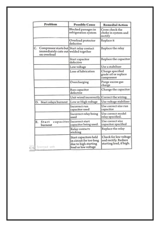
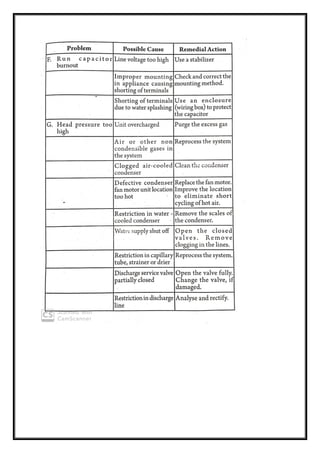
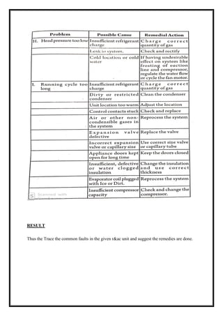
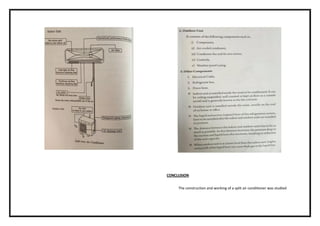
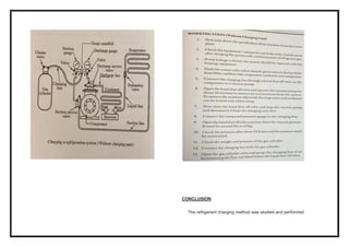
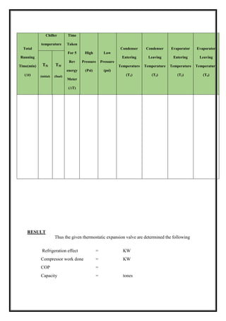
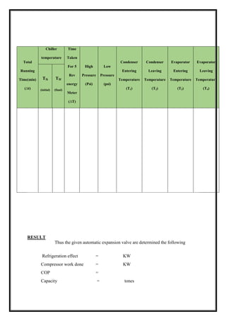
The experiment determined the refrigerating effect, COP, and capacity of an open refrigeration system using a thermostatic expansion valve by running the system until steady-state was reached, recording temperature and pressure readings, calculating the total refrigerating effect based on the water temperature drop and mass of water, and determining the compressor work done and COP using formulas involving the energy meter reading and constants.

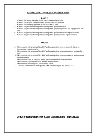

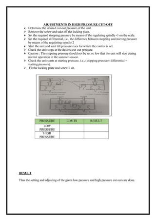

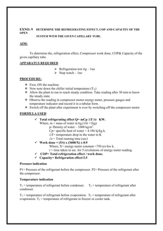
![EXNO: 11 DETERMINE THE COP OF THE GIVEN SEALED SYSTEM USING
ELECTRICAL MEASUREMENTS (WINDOWS AIR CONDITIONER)
AIM
To determine the cop of the given sealed system using electrical measurements
(windows air conditioner)
APPARATUS REQUIRED
Air – conditioning test rig -1no
Stop watch -1no
PROCEDURE
Switch on the mains.
Switch on the condenser, fan and blower.
Switch on the compressor and allow the unit to stabilize or 30 min.
Note down the following.
A] Pressure P1, P2 from the respective pressure gauge.
B] Note the corresponding temperature T1, T2, T3, T4, T5, and T6 at the
respective state points.
C] Note the corresponding voltmeter and ammeter reading.
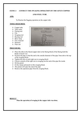
TABULATION
Total
Running
time
(min)
Voltmeter
reading
(volts)
Ammeter
Reading
(Amps)
Pressure
reading
(psi)
Temp reading (0
C)
Velocity
Of air
P1 P2 T1 T2 T3 T4 T5 T6 m/sec](https://image.slidesharecdn.com/raclabmannualfinal-220530153436-146734c2/85/R-AC-LAB-MANNUAL-FINAL-docx-pdf-50-320.jpg)
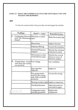
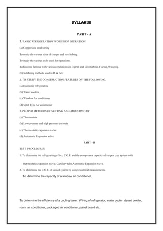
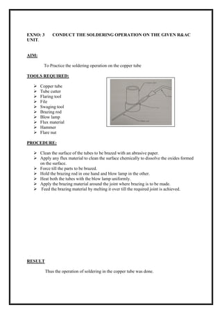
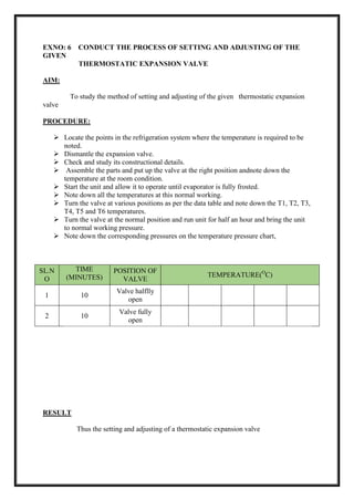
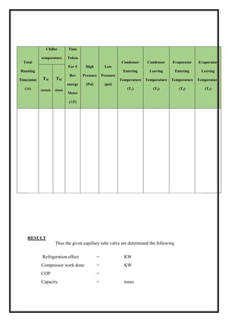
![SPECIFICATION
Compressor details type : 1 ton sealed closed type
Cylinder : single
Refrigerant : R 22
Condenser details : Air cooled
No of passes : 6mm or 1/4”
Pressure drop : 0.5 kg-f / cm2
Expansion device : Capillary tube and thermos tic expansion valve.
Tube material : Copper
Fan : Two nos
230 volts 2 amps : (for condenser and evaporators)
Energy meter : Single phase 230 volts , volt meter and amp.
FORMULA
Mass of air [m] = ρa x A x Va kg/sec
Where, ρa - density of air = 1.125 kg/m3
A - Area of the duct = LXB in m2
Va - Velocity of air in m/sec
Refrigeration effect = m [h2 – h1] kW
Where, ma - mass of air kg/sec
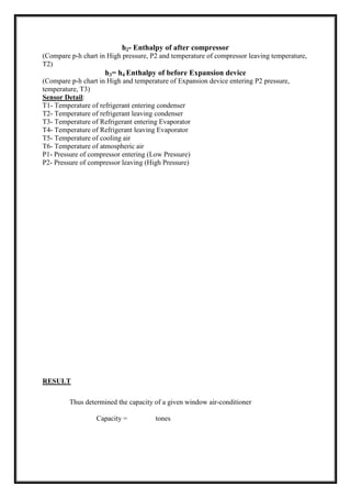
h1 - Enthalpy of before compressor (Refer P-h chart for r22)
h2- Enthalpy of After compressor (Refer P- h chart for r22)
Capacity = Refrigeration effect/3.5
Compressor Work done = ((V X I)/1000) X P.F
Where,
V - Voltmeter reading in volts
I- Ammeter reading in amps
P.F- Power factor = 0,9
COP = [h1- h3]/[ h2- h1]
[Where are h1, h2, h3 enthalpies of refrigerant taken from p-h chart for r22]
h1 - Enthalpy of before compressor
(Compare p-h chart in Low pressure, P1and temperature of compressor entering
temperature,T1)
h2- Enthalpy of after compressor
(Compare p-h chart in High pressure, P2 and temperature of compressor leaving temperature,
T2)](https://image.slidesharecdn.com/raclabmannualfinal-220530153436-146734c2/85/R-AC-LAB-MANNUAL-FINAL-docx-pdf-51-320.jpg)
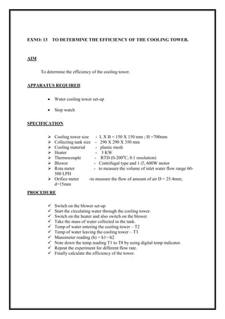
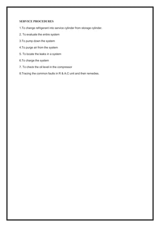
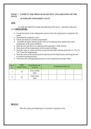
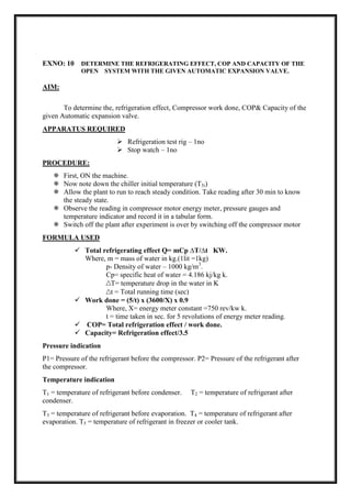
![EXNO: 12 DETERMINE THE CAPACITY OF A GIVEN WINDOW AIR-
CONDITIONER
AIM
Determine the capacity of a given window air-conditioner
APPARATUS REQUIRED
Air – conditioning test rig -1no
Stop watch -1no
PROCEDURE
Switch on the mains.
Switch on the condenser, fan and blower.
Switch on the compressor and allow the unit to stabilize or 30 min.
Note down the following.
A] Pressure P1, P2 from the respective pressure gauge.
B] Note the corresponding temperature T1, T2, T3, T4, T5, and T6 at the
respective state points.
C] Note the corresponding voltmeter and ammeter reading.
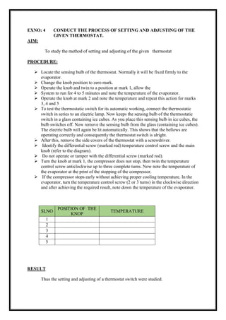
TABULATION
Total
Running
time
(min)
Voltmeter
reading
(volts)
Ammeter
Reading
(Amps)
Pressure
reading
(psi)
Temp reading (0
C)
Velocity
Of air
P1 P2 T1 T2 T3 T4 T5 T6 m/sec](https://image.slidesharecdn.com/raclabmannualfinal-220530153436-146734c2/85/R-AC-LAB-MANNUAL-FINAL-docx-pdf-53-320.jpg)
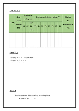
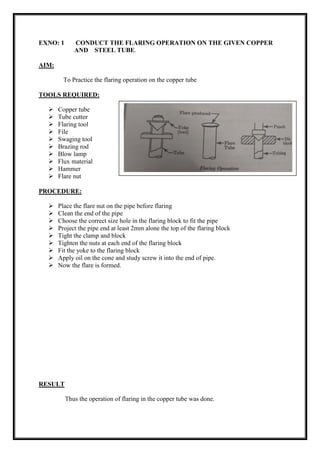
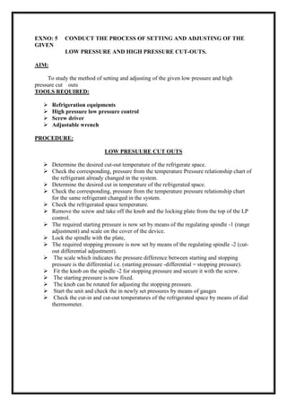
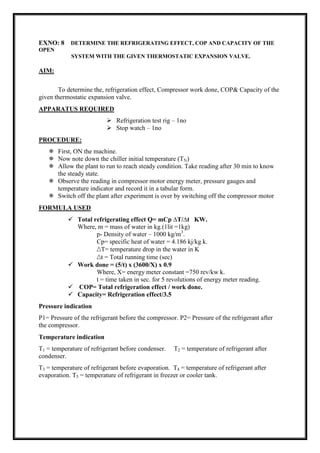
![SPECIFICATION
Compressor details type : 1 ton sealed closed type
Cylinder : single
Refrigerant : R 22
Condenser details : Air cooled
No of passes : 6mm or 1/4”
Pressure drop : 0.5 kg-f / cm2
Expansion device : Capillary tube and thermos tic expansion valve.
Tube material : Copper
Fan : Two nos
230 volts 2 amps : (for condenser and evaporators)
Energy meter : Single phase 230 volts , volt meter and amp.
FORMULA
Mass of air [m] = ρa x A x Va kg/sec
Where, ρa - density of air = 1.125 kg/m3
A - Area of the duct = LXB in m2
Va - Velocity of air in m/sec
Refrigeration effect = m [h2 – h1] kW
Where, ma - mass of air kg/sec
h1 - Enthalpy of before compressor (Refer P-h chart for r22)
h2- Enthalpy of After compressor (Refer P- h chart for r22)
Capacity = Refrigeration effect/3.5
Compressor Work done = ((V X I)/1000) X P.F
Where,
V - Voltmeter reading in volts
I- Ammeter reading in amps
P.F- Power factor = 0.9
COP = [h1- h3]/[ h2- h1]
[Where are h1, h2, h3 enthalpies of refrigerant taken from p-h chart for r22]
h1 - Enthalpy of before compressor
(Compare p-h chart in Low pressure, P1and temperature of compressor entering
temperature,T1)](https://image.slidesharecdn.com/raclabmannualfinal-220530153436-146734c2/85/R-AC-LAB-MANNUAL-FINAL-docx-pdf-54-320.jpg)