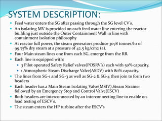
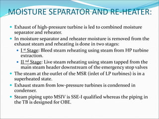
FUNCTION:
ď‚— To transfer the heat produced in the reactor to turbo-
generator for production of electrical power
ď‚— Acts as a heat sink for the PHT system and provides a
reliable means of removal of heat from primary
coolant under various conditions of reactor operation
SYSTEM DESCRIPTION:
 Feed water enters the SG after passing through the SG level CV’s.
ď‚— An isolating MV is provided on each feed water line entering the reactor
building just outside the Outer Containment Wall in line with
containment isolation philosophy
ď‚— At reactor full power, the steam generators produce 3078 tonnes/hr of
99.75% dry steam at a pressure of 42.5 kg/cm2 (a).
ď‚— Four Main steam lines one from each SG, emerge from the RB.
ď‚— Each line is equipped with:
 3 Pilot operated Safety Relief valves(POSRV’s) each with 50% capacity.
ď‚— 1 Atmospheric Steam Discharge Valve(ASDV) with 80% capacity.
ď‚— The lines from SG-1 and SG-3 as well as SG-2 & SG-4 then join to form two
headers
ď‚— Each header has a Main Steam Isolating Valve(MSIV),Steam Strainer
followed by an Emergency Stop and Control Valve(ESCV)
ď‚— Both headers are interconnected by an interconnecting line to enable on-
load testing of ESCV’s.
 The steam enters the HP turbine after the ESCV’s
MOISTURE SEPARATOR AND RE-HEATER:
ď‚— Exhaust of high-pressure turbine is led to combined moisture
separator and reheater.
ď‚— In moisture separator and reheater moisture is removed from the
exhaust steam and reheating is done in two stages:
ď‚— I st Stage: Bleed steam reheating using steam from HP turbine
extraction.
ď‚— II nd Stage: Live steam reheating using steam tapped from the
main steam header downstream of the emergency stop valves
ď‚— The steam at the outlet of the MSR (inlet of LP turbines) is in a
superheated state.
ď‚— Exhaust steam from low-pressure turbines is condensed in
condenser.
ď‚— Steam piping upto MSIV is SSE-I qualified whereas the piping in
the TB is designed for OBE.
TAPPINGS FROM THE MAIN STEAM LINE:
 Line to Condenser Steam Dump Valves (CSDV’s)
ď‚— Second stage re-heating of HP exhaust (Live Steam Re-
heater).Tapping taken from downstream of Emergency
Stop valve.
ď‚— Pegging Steam line for deaerator for initial heating
and pressure control during transients
ď‚— Steam supply for turbine gland sealing is tapped from
the pegging steam line upstream of the CV’s
ď‚— Steam supply line to Upgrading Plant and Waste
Management Plant.
MAJOR EQUIPMENTS:
STEAM GENERATOR
ď‚— Tube Side: PHT
ď‚— Shell side: Feed water/ Steam
ď‚— The steam coming out of SG will be 99.75% dry (0.25%
wet).
ď‚— SG variable pressure program to prevent large
swell/shrinkage on the primary side
ď‚— SG level control: Level setpoint varies with power
ď‚— Turbine trip on SG level high: 14.25 m to prevent carry over
of water droplets into the turbine.
ď‚— Reactor trip on SG level Low: 7.8 m to ensure the
availability of minimum SG inventory required for the
cooldown of PHT system
EMERGENCY SUPPLY TO SG’s:
ď‚— In case of rare events involving loss of feed water to the SGs such
as following a station black out or simultaneous failure of Class-
IV power supply and both ABFPs, emergency feed is given to SGs
through auxiliary feed nozzle from the Fire Water System VIA
MV’s located inside the SG room
ď‚— Additional fire water line is hooked up at the discharge header of
ABFP going to each SG with two nos. valves in series which are
kept chain locked and ensured closed normally.
 In the event of a station blackout fire water injection to the SG’s
will commence when SG pressure drops to 5 kg/cm2 using 3
diesel fire water pumps.
PILOT OPERATED SAFETY VALVES
(3611-RV-1 TO 12)
ď‚— 3 nos. connected to each of the four lines
ď‚— Totally they are capable of relieving 150% full power
flow
ď‚— Main steam safety relief valves are set at following
pressure:
ď‚— 3611-RV-4, 10, 7, 1-53 kg/cm2(g)
ď‚— 3611-RV-5, 11, 8, 2-55 kg/cm2(g)
ď‚— 3611-RV-6, 12, 9, 3-57 kg/cm2(g)
ď‚— They can be operated manually from main control
room
ATMOSPHERIC STEAM DISCHARGE
VALVE (3611-CV-17 TO 20):
ď‚— Atmospheric steam discharge valve is a control valve
discharging steam to atmosphere.
ď‚— One valve one each of the four steam headers
ď‚— Operates on SGPC signal.
ď‚— Also used for the controlled cool down of PHT System
ď‚— Fail safe condition: Air fail to open
ď‚— Local air accumulator has been provided for all ASDVs,
which will provide air supply for 30 mins in case of
failure of Cl-III instrument air. ASDV’s will open on air
failure after 30. mins
Condenser Steam Dump Valves(4221-V-1 to 4):
ď‚— A turbine bypass system is provided to bypass steam to the
condenser as an alternate path for steam in the event of
discrepancy between steam flow from the steam generators and
steam flow requirement of the turbine
ď‚— Such discrepancies in steam flows would occur on (i)plant start-
up, (ii) shut down, (iii) load rejection, (iv) turbine trip
ď‚— Controlled by SGPC signal
ď‚— Valves all together designed to handle 70% of the main steam
flow generated by the steam generator at a normal pressure of
42.5 kg/cm2(a)
ď‚— Each CSDV comprises of combined stop and control valves
operated hydraulically
ď‚— De-superheating water supply provided at the downstream of
each CSDV to prevent superheating of steam when it is diverted
to the condenser
MAIN STEAM ISOLATING VALVE
(MSIV) (3611-MV-1, 2):
ď‚— The MSIV is introduced in the main steam piping in
order to create a pressure boundary between safety
class pipe work and the non-nuclear safety piping
ď‚— They serve the purpose of containment isolation on
main steam line
Emergency Stop and Control Valves
(3611-V-1 & V-2):
ď‚— Each ESCV comprises of combined stop and
control valves operated hydraulically
ď‚— Final control elements of the electro hydraulic
governing system
QudgsvsshzhshxhdhxdMAIN STEAM SYSTEM.ppt

QudgsvsshzhshxhdhxdMAIN STEAM SYSTEM.ppt

  • 2.
    FUNCTION: ď‚— To transferthe heat produced in the reactor to turbo- generator for production of electrical power ď‚— Acts as a heat sink for the PHT system and provides a reliable means of removal of heat from primary coolant under various conditions of reactor operation
  • 3.
    SYSTEM DESCRIPTION:  Feedwater enters the SG after passing through the SG level CV’s.  An isolating MV is provided on each feed water line entering the reactor building just outside the Outer Containment Wall in line with containment isolation philosophy  At reactor full power, the steam generators produce 3078 tonnes/hr of 99.75% dry steam at a pressure of 42.5 kg/cm2 (a).  Four Main steam lines one from each SG, emerge from the RB.  Each line is equipped with:  3 Pilot operated Safety Relief valves(POSRV’s) each with 50% capacity.  1 Atmospheric Steam Discharge Valve(ASDV) with 80% capacity.  The lines from SG-1 and SG-3 as well as SG-2 & SG-4 then join to form two headers  Each header has a Main Steam Isolating Valve(MSIV),Steam Strainer followed by an Emergency Stop and Control Valve(ESCV)  Both headers are interconnected by an interconnecting line to enable on- load testing of ESCV’s.  The steam enters the HP turbine after the ESCV’s
  • 4.
    MOISTURE SEPARATOR ANDRE-HEATER: ď‚— Exhaust of high-pressure turbine is led to combined moisture separator and reheater. ď‚— In moisture separator and reheater moisture is removed from the exhaust steam and reheating is done in two stages: ď‚— I st Stage: Bleed steam reheating using steam from HP turbine extraction. ď‚— II nd Stage: Live steam reheating using steam tapped from the main steam header downstream of the emergency stop valves ď‚— The steam at the outlet of the MSR (inlet of LP turbines) is in a superheated state. ď‚— Exhaust steam from low-pressure turbines is condensed in condenser. ď‚— Steam piping upto MSIV is SSE-I qualified whereas the piping in the TB is designed for OBE.
  • 5.
    TAPPINGS FROM THEMAIN STEAM LINE:  Line to Condenser Steam Dump Valves (CSDV’s)  Second stage re-heating of HP exhaust (Live Steam Re- heater).Tapping taken from downstream of Emergency Stop valve.  Pegging Steam line for deaerator for initial heating and pressure control during transients  Steam supply for turbine gland sealing is tapped from the pegging steam line upstream of the CV’s  Steam supply line to Upgrading Plant and Waste Management Plant.
  • 6.
  • 7.
    STEAM GENERATOR ď‚— TubeSide: PHT ď‚— Shell side: Feed water/ Steam ď‚— The steam coming out of SG will be 99.75% dry (0.25% wet). ď‚— SG variable pressure program to prevent large swell/shrinkage on the primary side ď‚— SG level control: Level setpoint varies with power ď‚— Turbine trip on SG level high: 14.25 m to prevent carry over of water droplets into the turbine. ď‚— Reactor trip on SG level Low: 7.8 m to ensure the availability of minimum SG inventory required for the cooldown of PHT system
  • 8.
    EMERGENCY SUPPLY TOSG’s:  In case of rare events involving loss of feed water to the SGs such as following a station black out or simultaneous failure of Class- IV power supply and both ABFPs, emergency feed is given to SGs through auxiliary feed nozzle from the Fire Water System VIA MV’s located inside the SG room  Additional fire water line is hooked up at the discharge header of ABFP going to each SG with two nos. valves in series which are kept chain locked and ensured closed normally.  In the event of a station blackout fire water injection to the SG’s will commence when SG pressure drops to 5 kg/cm2 using 3 diesel fire water pumps.
  • 12.
    PILOT OPERATED SAFETYVALVES (3611-RV-1 TO 12) ď‚— 3 nos. connected to each of the four lines ď‚— Totally they are capable of relieving 150% full power flow ď‚— Main steam safety relief valves are set at following pressure: ď‚— 3611-RV-4, 10, 7, 1-53 kg/cm2(g) ď‚— 3611-RV-5, 11, 8, 2-55 kg/cm2(g) ď‚— 3611-RV-6, 12, 9, 3-57 kg/cm2(g) ď‚— They can be operated manually from main control room
  • 13.
    ATMOSPHERIC STEAM DISCHARGE VALVE(3611-CV-17 TO 20):  Atmospheric steam discharge valve is a control valve discharging steam to atmosphere.  One valve one each of the four steam headers  Operates on SGPC signal.  Also used for the controlled cool down of PHT System  Fail safe condition: Air fail to open  Local air accumulator has been provided for all ASDVs, which will provide air supply for 30 mins in case of failure of Cl-III instrument air. ASDV’s will open on air failure after 30. mins
  • 14.
    Condenser Steam DumpValves(4221-V-1 to 4): ď‚— A turbine bypass system is provided to bypass steam to the condenser as an alternate path for steam in the event of discrepancy between steam flow from the steam generators and steam flow requirement of the turbine ď‚— Such discrepancies in steam flows would occur on (i)plant start- up, (ii) shut down, (iii) load rejection, (iv) turbine trip ď‚— Controlled by SGPC signal ď‚— Valves all together designed to handle 70% of the main steam flow generated by the steam generator at a normal pressure of 42.5 kg/cm2(a) ď‚— Each CSDV comprises of combined stop and control valves operated hydraulically ď‚— De-superheating water supply provided at the downstream of each CSDV to prevent superheating of steam when it is diverted to the condenser
  • 15.
    MAIN STEAM ISOLATINGVALVE (MSIV) (3611-MV-1, 2): ď‚— The MSIV is introduced in the main steam piping in order to create a pressure boundary between safety class pipe work and the non-nuclear safety piping ď‚— They serve the purpose of containment isolation on main steam line
  • 16.
    Emergency Stop andControl Valves (3611-V-1 & V-2): ď‚— Each ESCV comprises of combined stop and control valves operated hydraulically ď‚— Final control elements of the electro hydraulic governing system