Download as PDF, PPTX
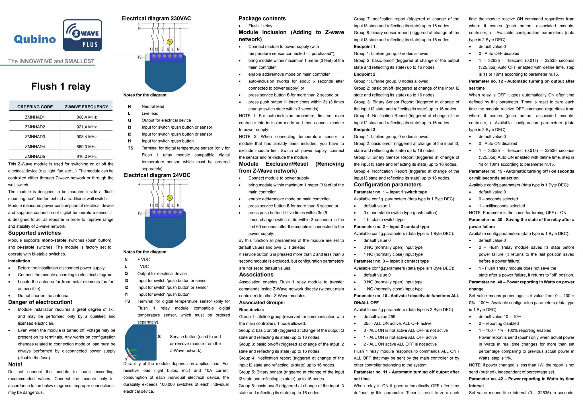

This document provides information about the Qubino Flush 1 relay Z-Wave module. The module can be used to switch electrical devices on or off through the Z-Wave network or a wall switch. It supports connection to a digital temperature sensor and can act as a repeater to improve the Z-Wave network range. The module measures power consumption and supports mono-stable and bi-stable switches. It provides information on inclusion into a Z-Wave network and configuration parameters for functions like power reporting and input settings.


![Coded Agents – with UiPath SDK + LangGraph [Virtual Hands-on Workshop]](https://cdn.slidesharecdn.com/ss_thumbnails/codedagentsdeck-251215155422-5497c599-thumbnail.jpg?width=640&height=640&fit=bounds)


![Vibe Coding vs. Spec-Driven Development [Free Meetup]](https://cdn.slidesharecdn.com/ss_thumbnails/vibecodingvsspecdrivendevelopment-251209105622-43f455e7-thumbnail.jpg?width=640&height=640&fit=bounds)


