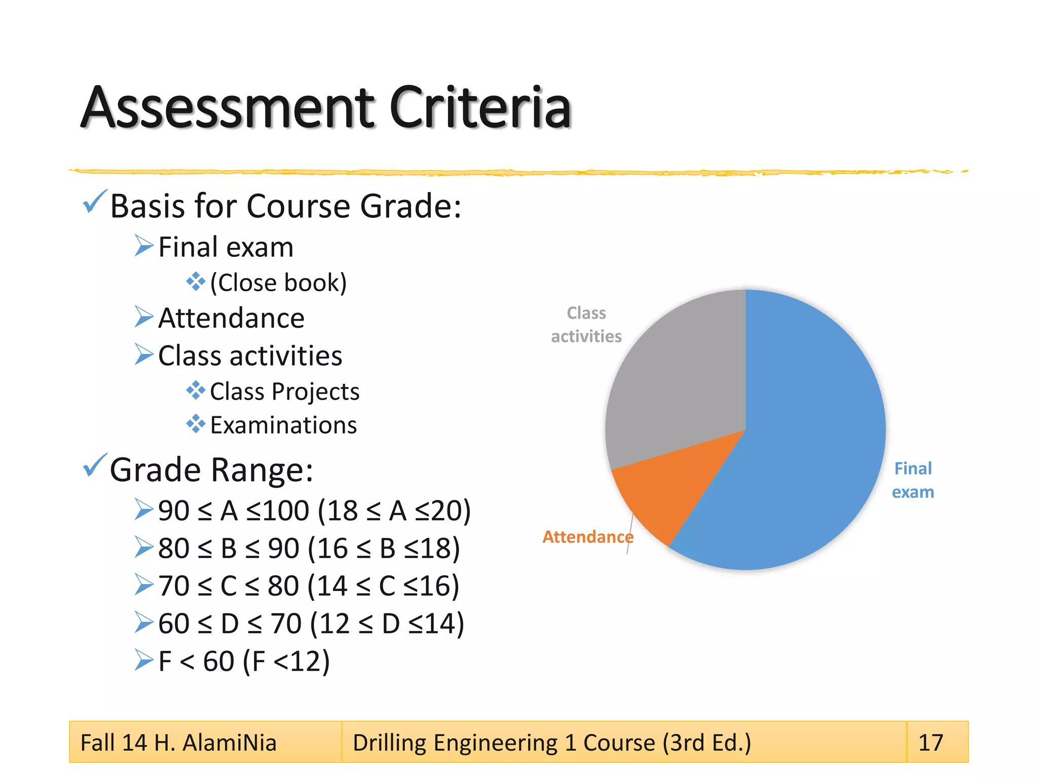
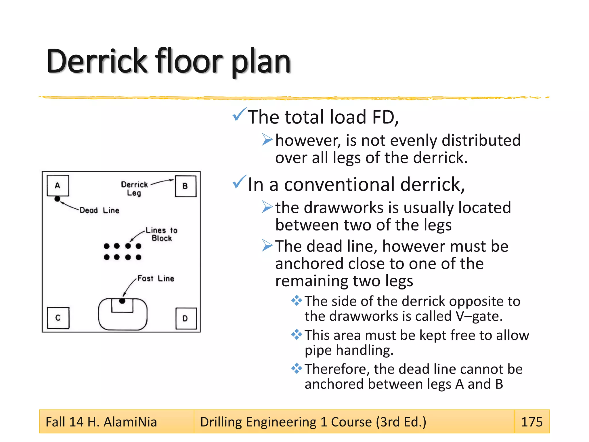
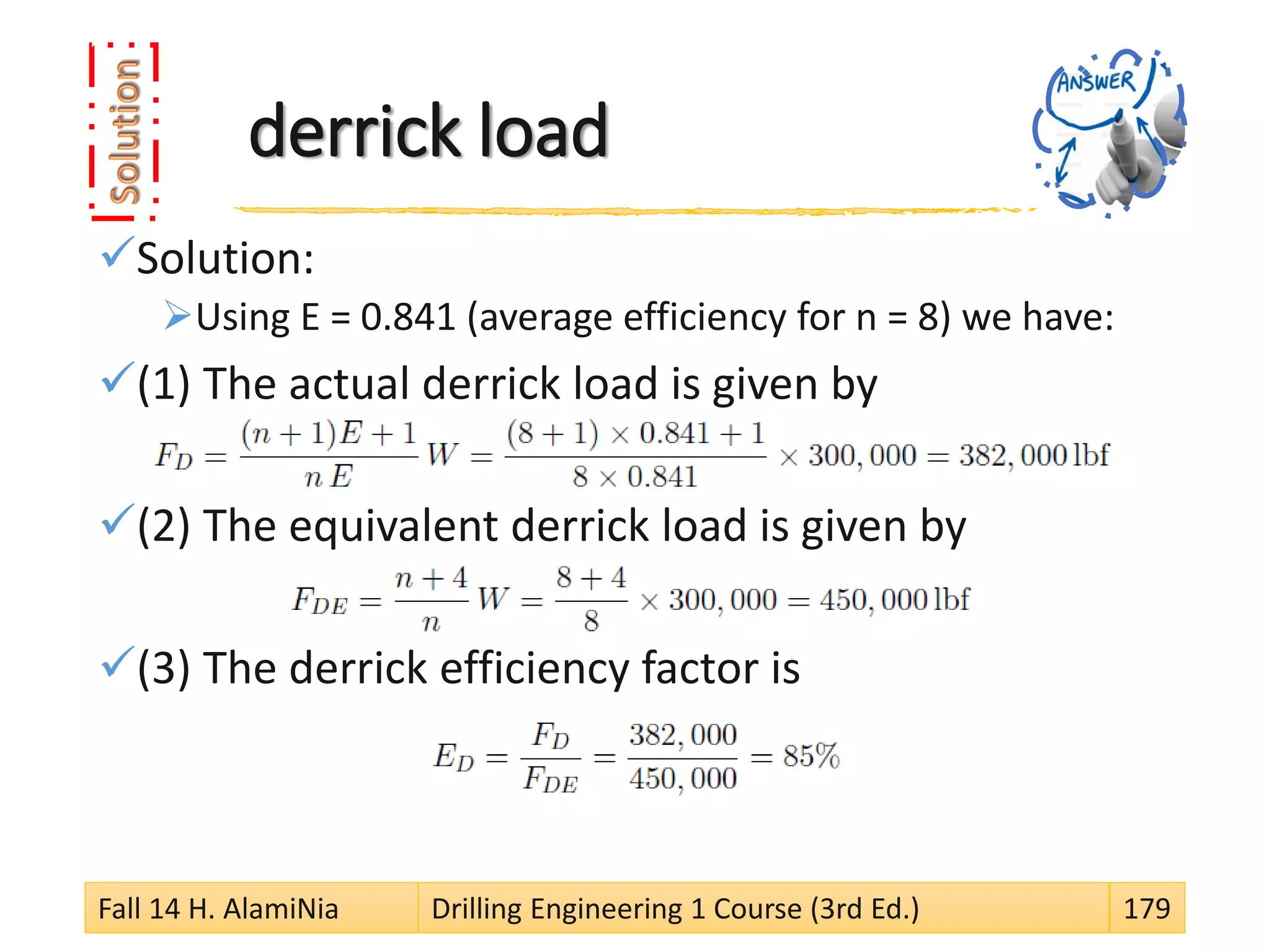
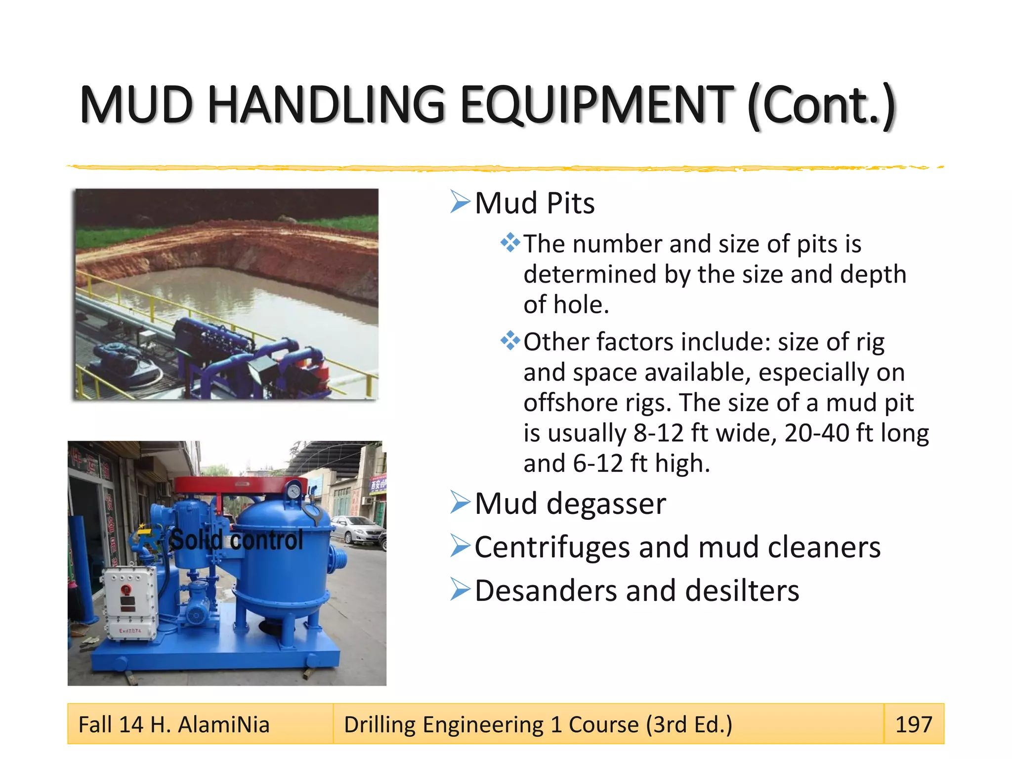
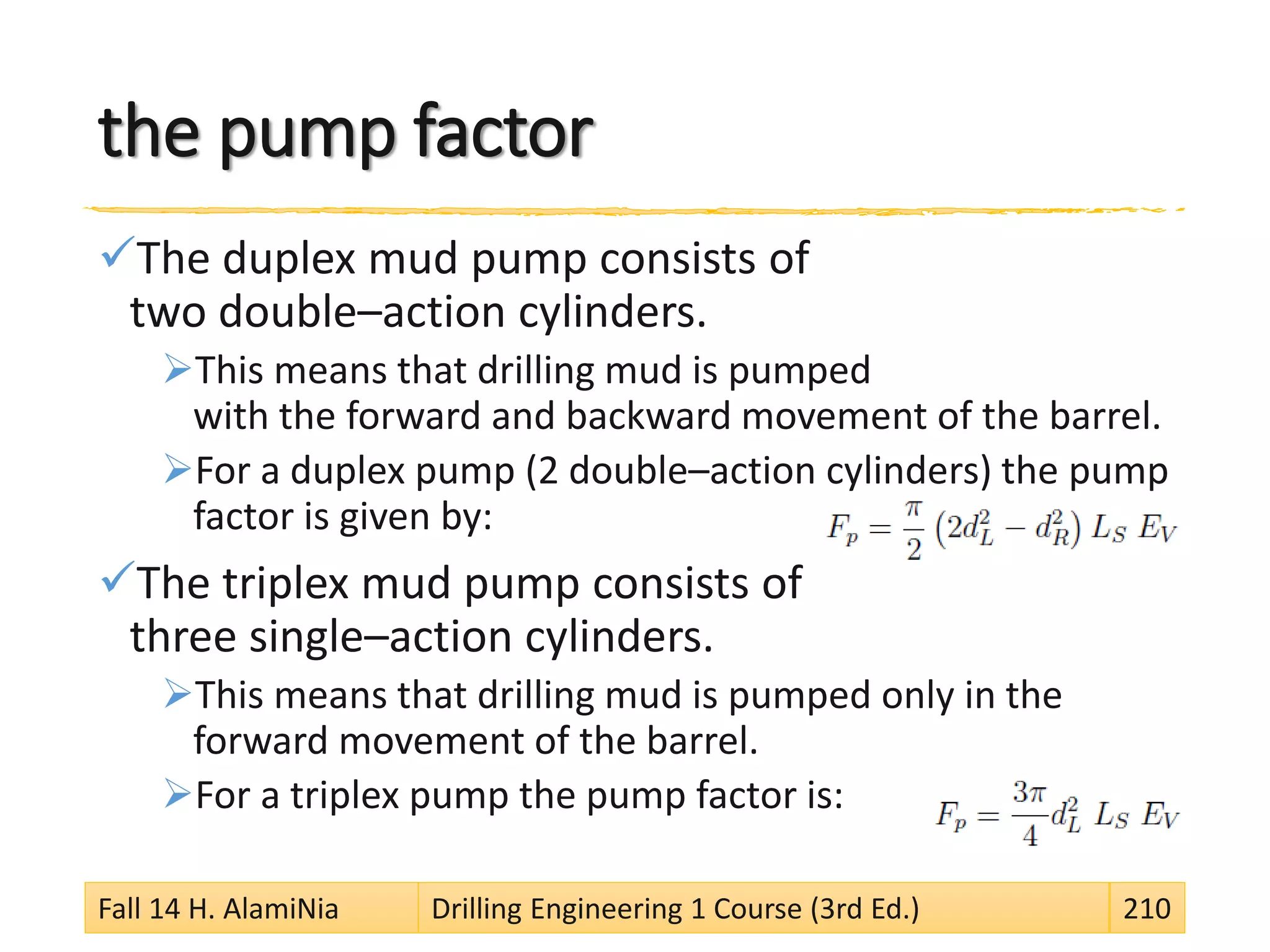
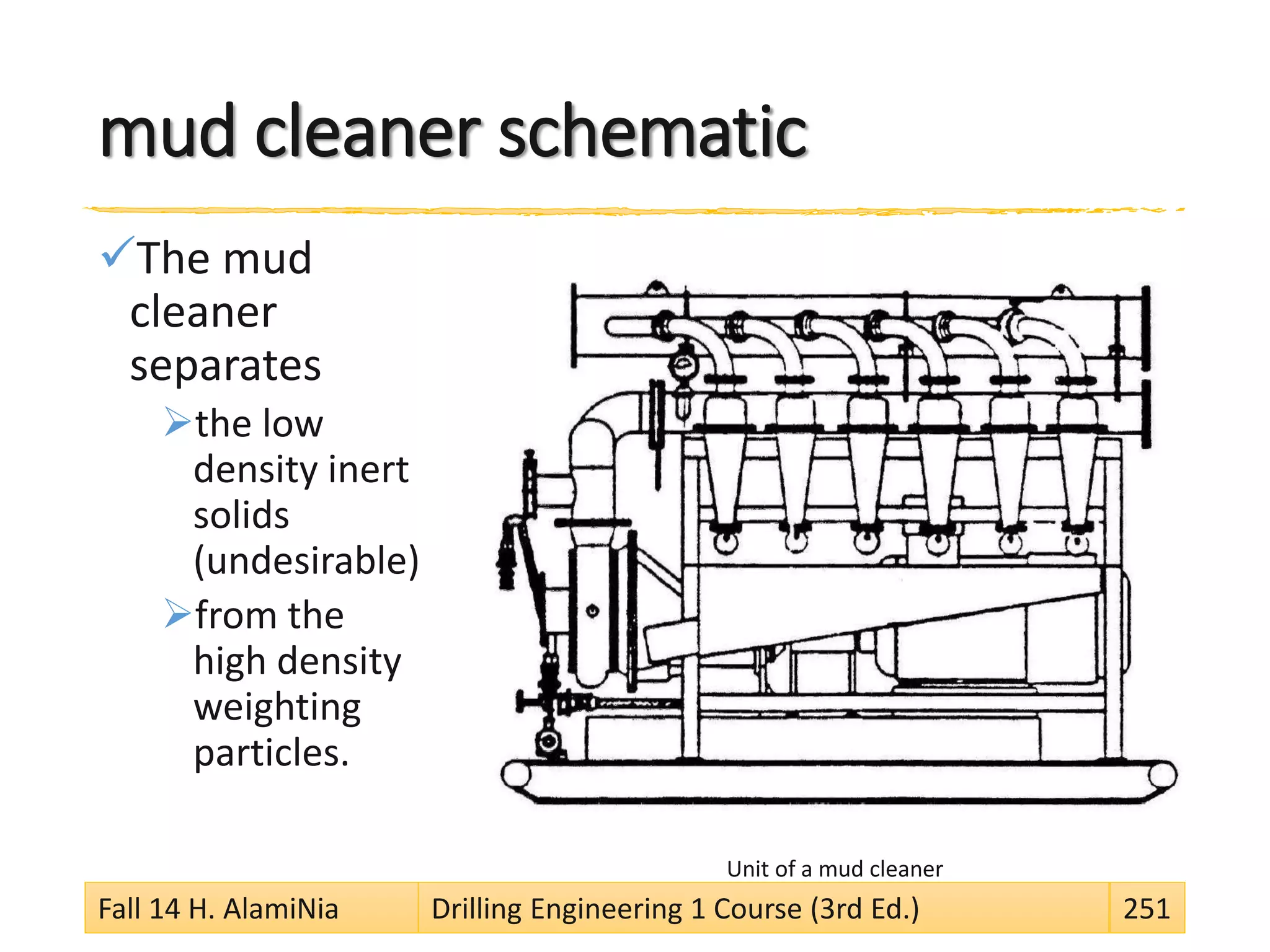
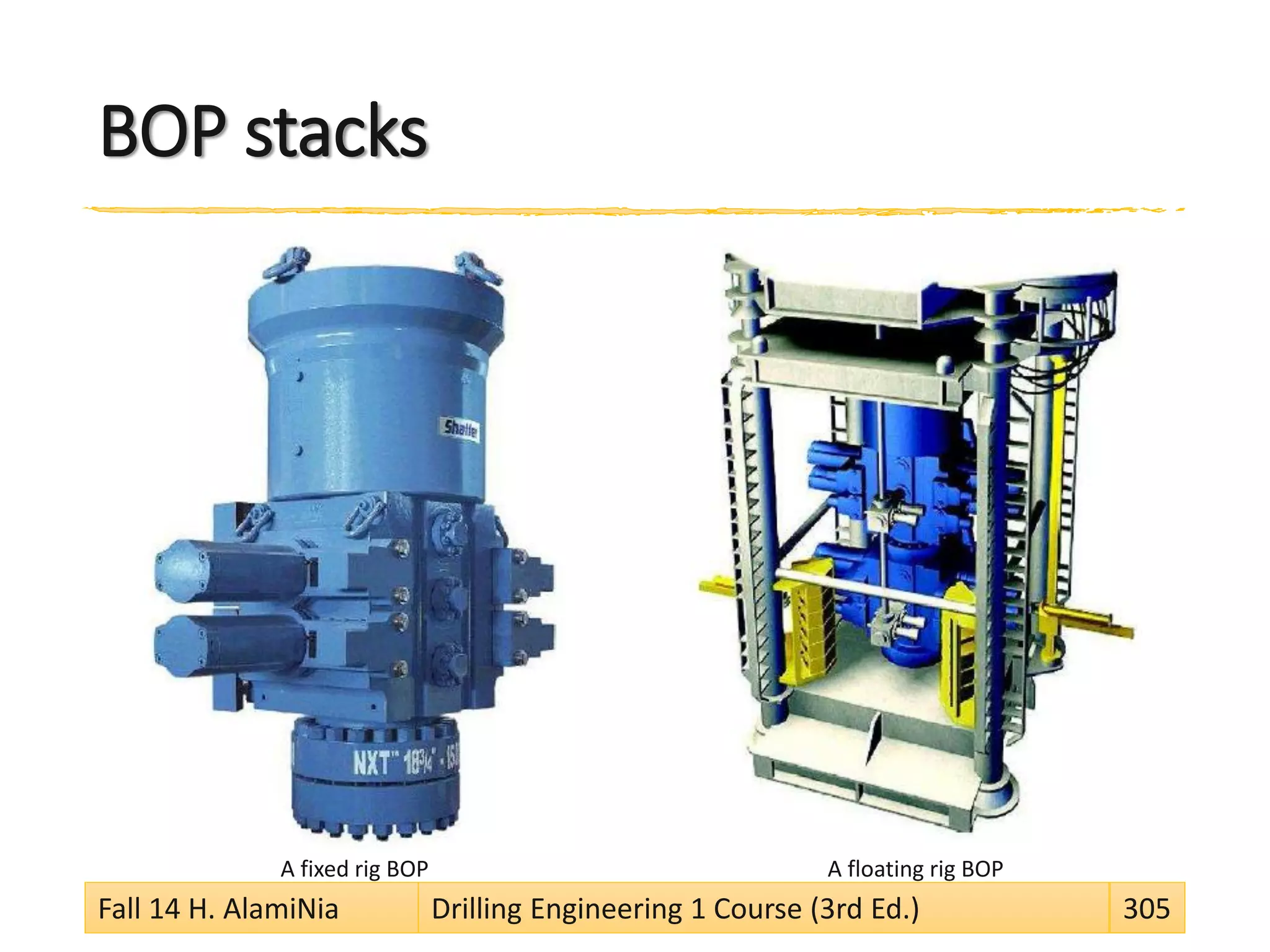
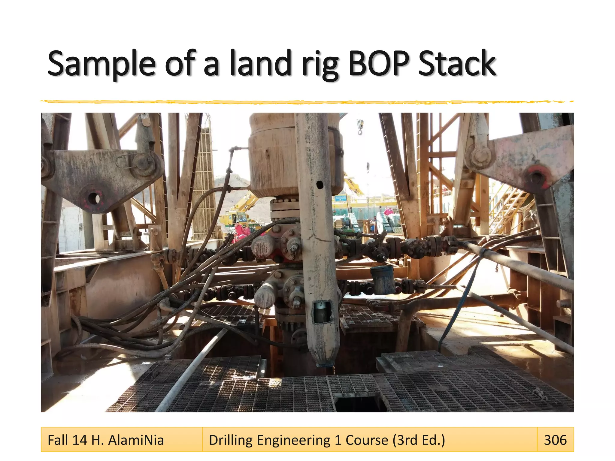
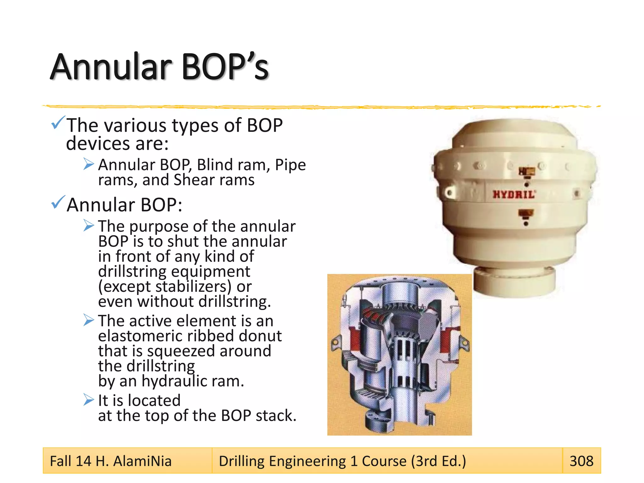
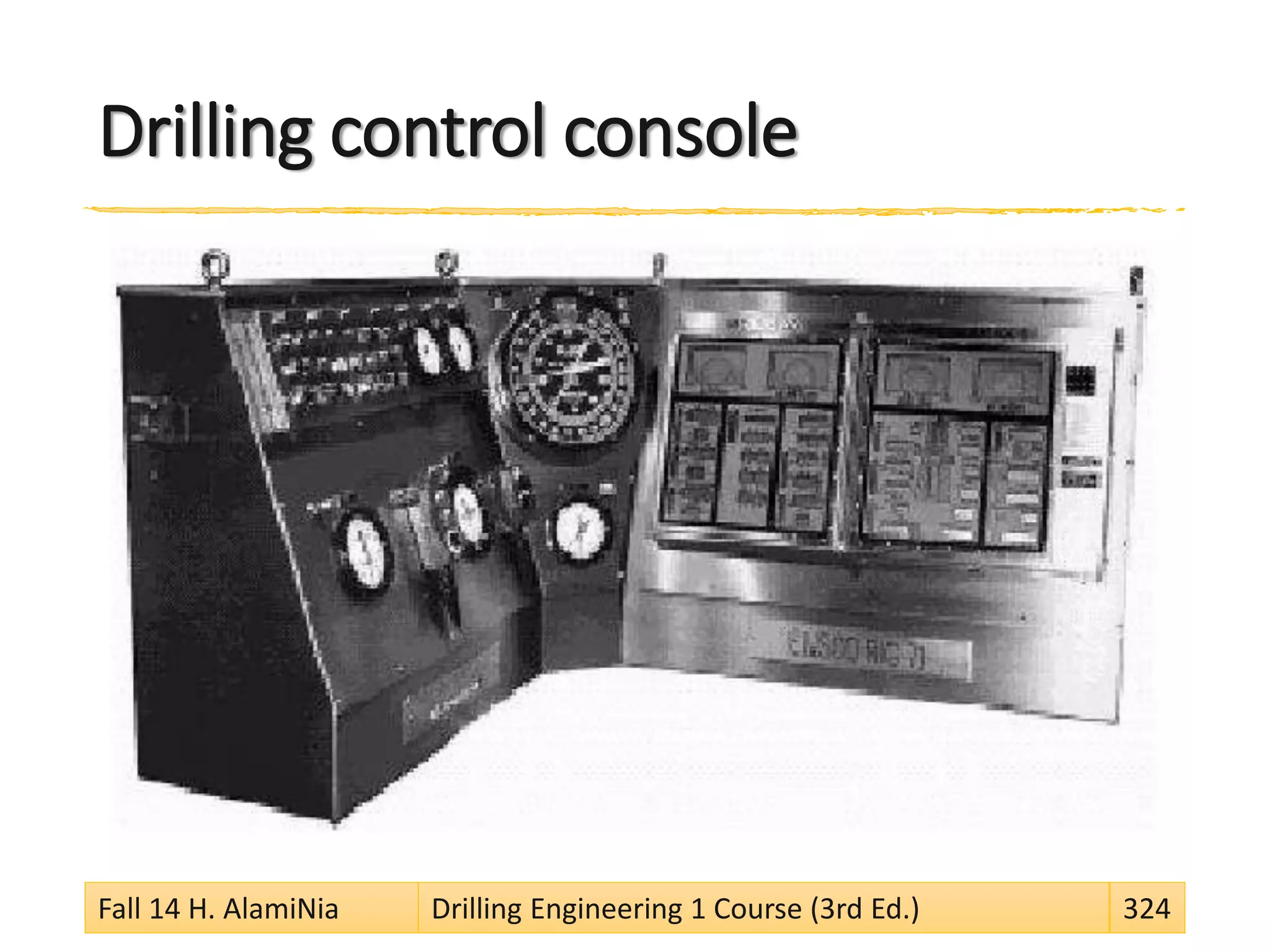
Download as PDF, PPTX


![Pump Power
Pumps convert mechanical power into hydraulic
power. From the definition of power P=Fv
In its motion,
the piston exerts a force [F] on the fluid that is equal to
the pressure differential in the piston Δp times
the area A of the piston, and
the velocity v is equal to
the flow rate q divided by the area A, that is
For PH in hp, p in psi, and q in gal/min (gpm) we have:
Fall 14 H. AlamiNia Drilling Engineering 1 Course (3rd Ed.) 214](https://image.slidesharecdn.com/vsfe5sektsovrlem3j35-signature-d9e691f50924050a5574af6cb5a87f49cf8ea1b64d07db8b8ce172e0273b2b58-poli-150131005207-conversion-gate02/75/Q931-de1-reference-en-lecs-214-2048.jpg)


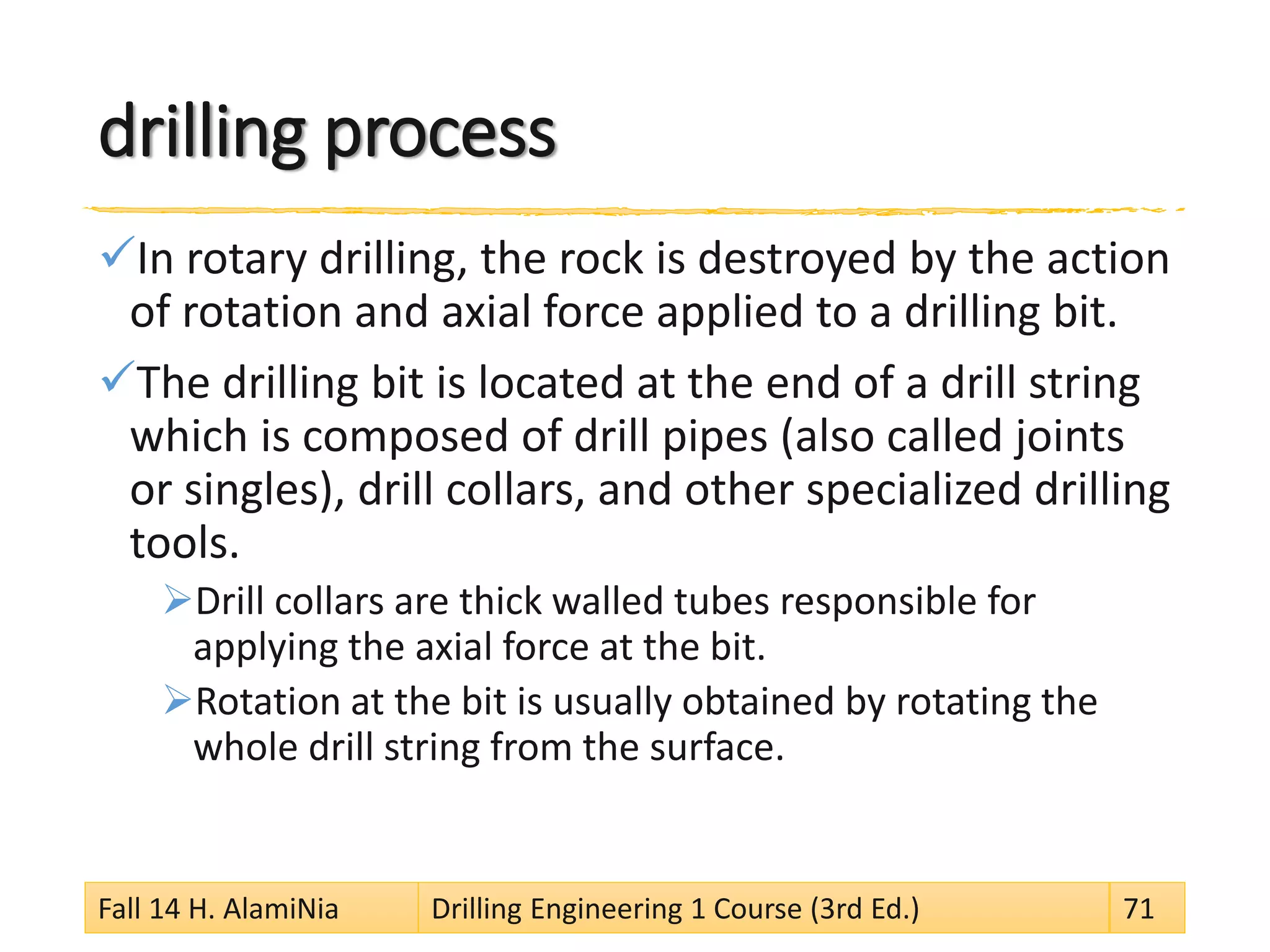
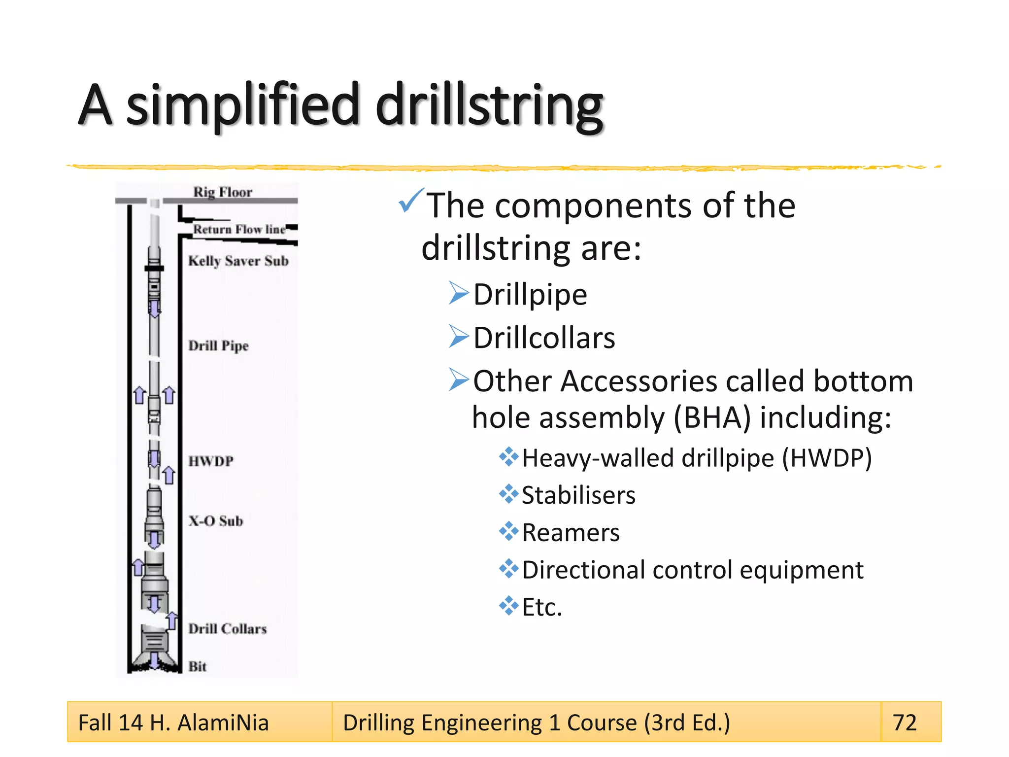
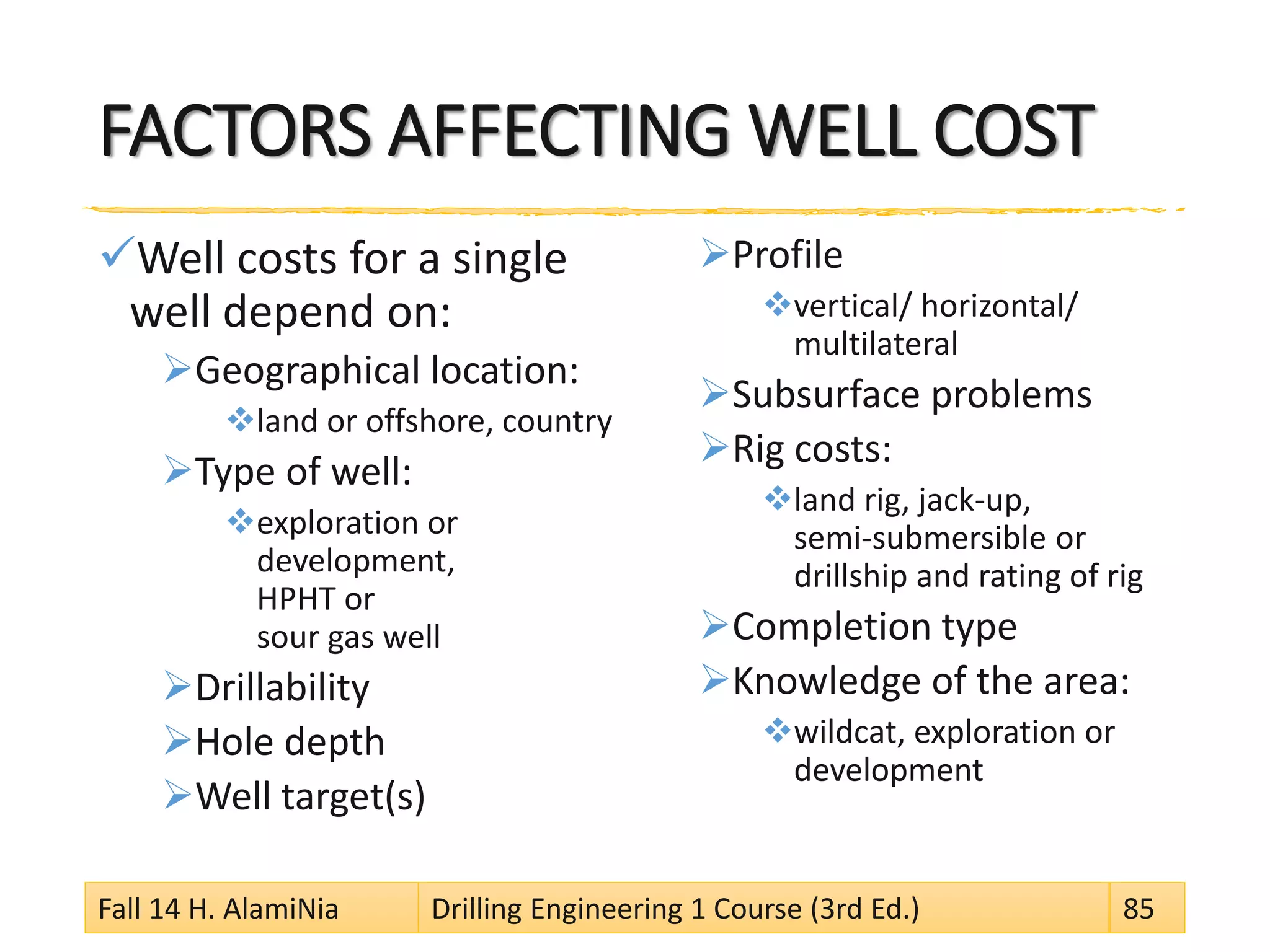
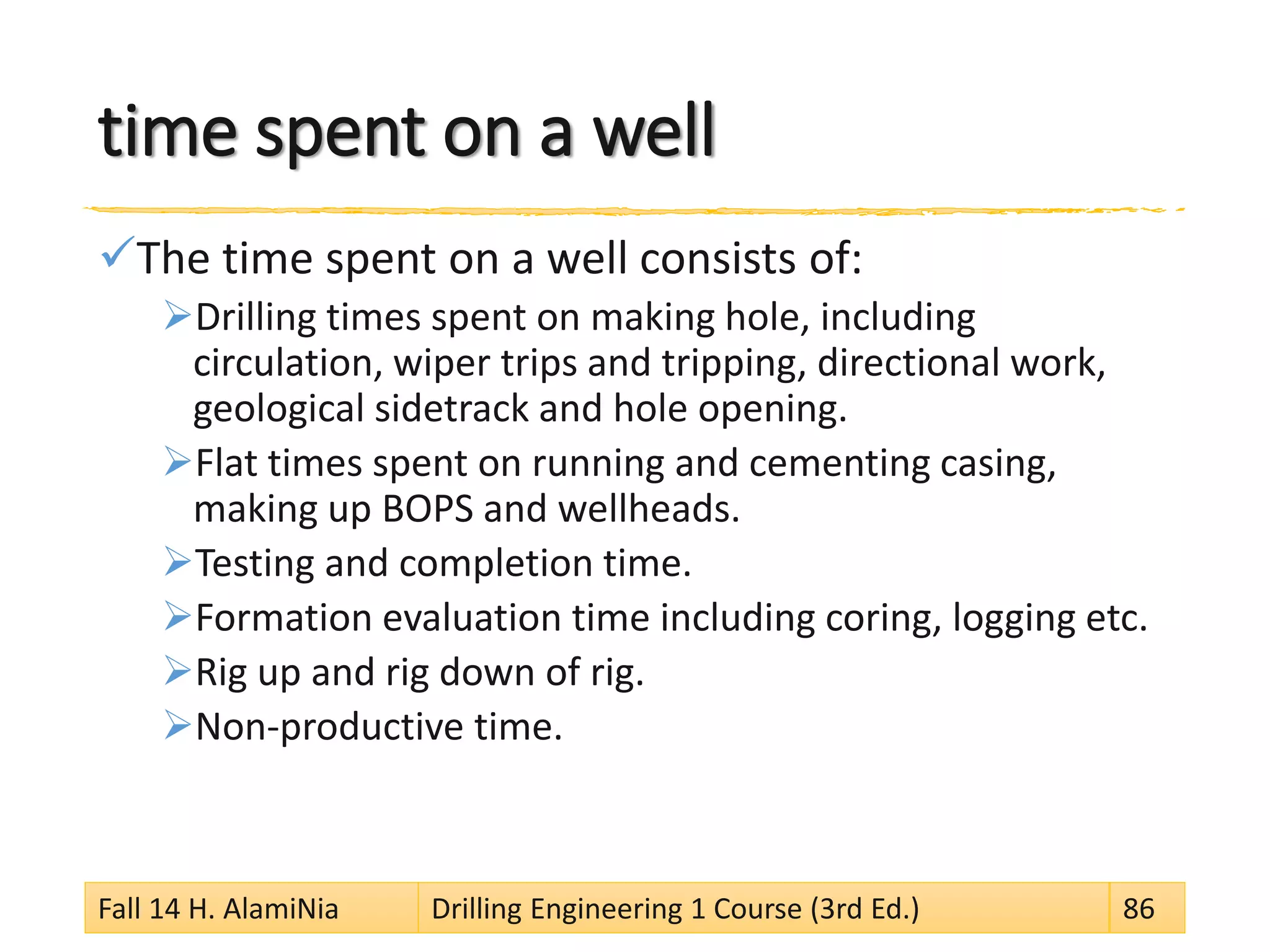
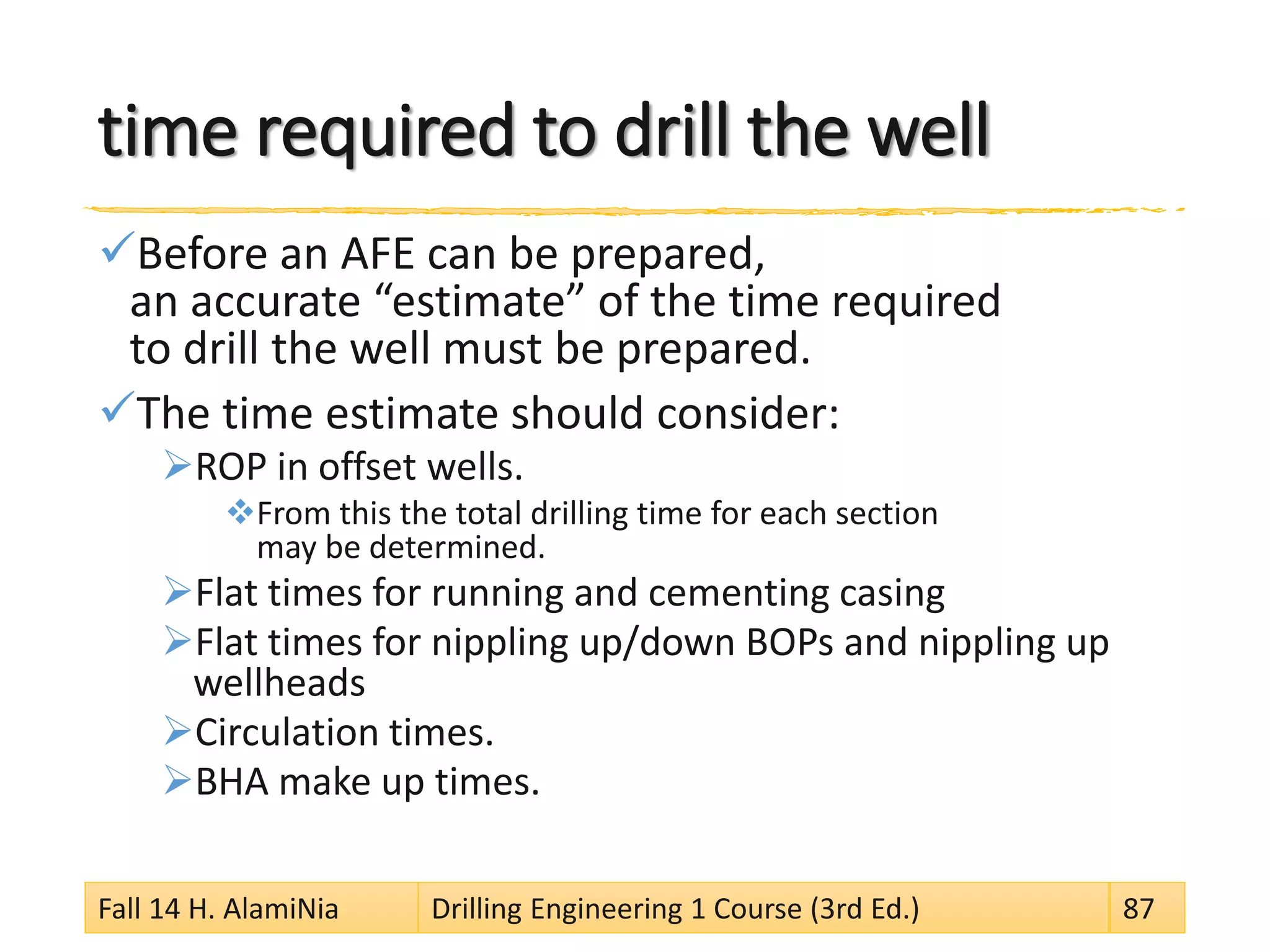
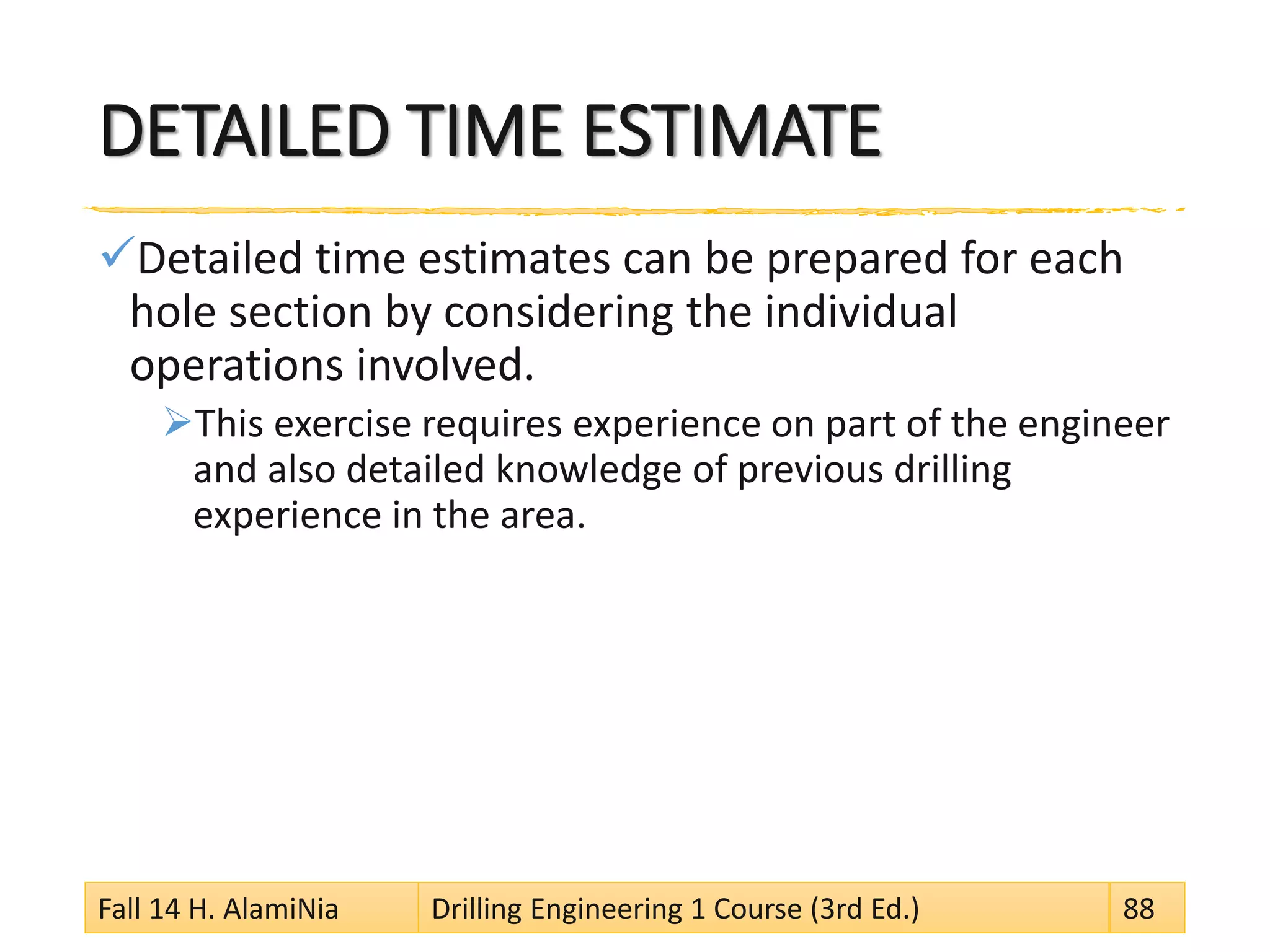
This document outlines the syllabus for a drilling engineering course. It covers topics such as an introduction to drilling operations and well construction, well classifications, personnel involved in drilling, rig components and calculations, drill strings, drill bits, and drilling fluid technologies. The course aims to provide a systematic theoretical and practical study of drilling engineering through lectures, tutorials, and class projects. Assessment will be based on a final exam, attendance, and class activities. The course is designed to teach both major and minor petroleum engineering students about key aspects of drilling operations.


