Download to read offline
![Yacoub Yousef Ahmad Alotaibi Int. Journal of Engineering Research and Applications www.ijera.com
ISSN: 2248-9622,Vol. 5, Issue 6, (Part -3) June 2015, pp.109-116
www.ijera.com 109|P a g e
Desalination technology; economy and simplicity
ENG/ Yacoub Yousef Ahmad Alotaibi
”Public Authority for Applied Education & Training"
Abstract
Water scarcity is a major problem, a seawater desalination process separates saline seawater into two streams: a
fresh water stream containing a low concentration of dissolved salts and a concentrated brine stream Applied
desalination technologies can be divided in to three groups, thermal desalination technologies, membrane based
desalination technologies,and solar desalination technologies. Results show that solar energy coupled to
desalination offers a promising prospect for covering the fundamental needs of power and water in remote
regions such as grid-limited villages or isolated islands that have access to sea or brackish-water. Reverse
osmosis (RO) and electrodialysis (ED) desalination units are the most favorable alternatives to be coupled with
photovoltaic (PV) systems.
Keywords: Seawater desalination technologies; Multi-stage flash distillation desalination; Multiple-effect
distillation desalination; Vapor compression distillation desalination; Reverse osmosis desalination; Solar
evaporation desalination; electrodialysis
Introduction
Desalination technologies can be classified by
their separation mechanism into thermal, membrane
and solar based desalination. Thermal desalination
separates salt from water by evaporation and
condensation, whereas in membrane desalination
water diffuses through a membrane, while salts are
almost completely retained. Solar desalination can
either be direct; use solar energy to produce distillate
directly in the solar collector, or indirect; combining
conventional desalination techniques, such as
multistage flash desalination(MSF), vapor
compression (VC), reverse osmosis (RO), membrane
distillation (MD) and electrodialysis, with solar
collectors for heat generation. Direct solar
desalination compared with the indirect technologies
requires large land areas and has a relatively low
productivity. It is however competitive to the indirect
desalination plants in small-scale production due to
its relatively low cost and simplicity.
Applied desalination technologies can be divided in
to three groups
1- Thermal desalination technologies
Multi-effect distillation (MED)
Multi-stage flash distillation (MSF)
Vapour compression distillation (VCD)
2- Membrane based desalination technologies
Reverse osmosis (RO)
Nanofiltration (NF)
Electrodialysis (ED)
3- Solar desalination technologies
Regenerative
Conventional
Double-glass-cover cooling
Thermal desalination technology was preferred in
the Middle East, reverse osmosis and multi-stage
flash are the techniques that are most widely used in
commercials due to the amount and the cost of the
product, Reverse osmosis (RO) is suitable for these
applications but it requires a continuous supply of
electrical or mechanical energy. Many developing
countries which suffer from water scarcity also lack
in resources which can generate these sources of
energy (fossil fuels Energy consumption of reverse
osmosis is the lowest among all options for seawater
desalination, making it most cost efficient in regions
with high energy cost [1]. Especially in brackish
water desalination, reverse osmosis offers great
advantages over thermal desalination technologies
due to its much lower energy consumption at low salt
concentration [2]. The variable cost of thermal
desalination plants is almost independent of feed
water salinity, while membrane process variable cost
is nearly proportional to the feed water salinity and
therefore lowers in brackish water than in seawater
desalination, making reverse osmosis and
electrodialysis the most economic processes [2].
However, some of these countries have an abundance
of solar energy. Solar photovoltaics (PV) can be used
to operate reverse osmosis units for small scale
applications in these countries. But it may not be
feasible due to the high cost of PV modules and
RESEARCH ARTICLE OPEN ACCESS](https://image.slidesharecdn.com/q5603109116-150803053634-lva1-app6891/85/Desalination-technology-economy-and-simplicity-1-320.jpg)
![Yacoub Yousef Ahmad Alotaibi Int. Journal of Engineering Research and Applications www.ijera.com
ISSN: 2248-9622,Vol. 5, Issue 6, (Part -3) June 2015, pp.109-116
www.ijera.com 110|P a g e
maintenance of RO systems [3]. A much simpler
option is to use the solar energy as a source of
thermal energy. This requires us to develop
desalination technologies which can use this energy
in an efficient way.
Photovoltaic (PV) is a rapidly developing technology with declining costs table (1). And the study of coupling
this technology with desalination methods has increased significantly in the last few decades. Moreover, the use
of this technology is an excellent choice for providing desalinated water for small communities in remote arid
areas and isolated islands that have access to sea or brackish-water. The reason includes the economic benefits
and the solar system’s modularity, low maintenance, low noise level, long life, and non-emission of greenhouse
gases [4]. Typical desalination methods that require electricity and could be well-suited to this technology are
reverse osmosis (RO) and electrodialysis(ED) figure (1). The coupling of these methods with solar PV systems
holds great promise for increasing water supplies in water-scarce regions [5].
1.1. PV-RO system
RO technology description Reverse osmosis is a form of filtration in which the filter is a semi-permeable
membrane that allows water, but not salt, to pass through. A typical RO system consists of four major
subsystems pretreatment system, high-pressure pump, membrane module, and post-treatmentsystem [6]. Fig. (2)
Is a schematic diagram of PV-RO system.](https://image.slidesharecdn.com/q5603109116-150803053634-lva1-app6891/85/Desalination-technology-economy-and-simplicity-2-320.jpg)
![Yacoub Yousef Ahmad Alotaibi Int. Journal of Engineering Research and Applications www.ijera.com
ISSN: 2248-9622,Vol. 5, Issue 6, (Part -3) June 2015, pp.109-116
www.ijera.com 111|P a g e
The RO membrane is semi-permeable, possessing a high degree of water permeability, but presents an
impenetrable barrier to salts. It has a large surface area for maximum flow and is extremely thin so that it offers
minimal resistance to water flow; but it is also sturdy enough to withstand the pressure of the feed stream [7]
Polymers currently used for manufacturing RO membranes are based on either cellulose acetates (cellulose
diacetate, cellulose triacetate, or combinations of the two) or polyamide polymers. Two types of RO membranes
commonly used commercially are spiral wound (SW) membranes and hollow-fiber (HF) membranes. Other
configurations, including tubular and plate-frame designs, are sometimes used in the food and dairy industries.
SW membrane elements are most commonly manufactured from a cellulose osmotic pressure is applied on salt
water (feed water) passing through the synthetic membrane pores separated from the salt. A concentrated salt
solution is retained for disposal. The RO process is effective for removing total dissolved solid (TDS)
concentrations of up to 50,000 parts per million (ppm), which can be applied for both brackish-water (1500–
10,000 ppm) and seawater (33,000– 45,000 ppm). It is currently the most widely used process for seawater
desalination. Feed water pretreatment is a critical factor in operating an RO system because membranes are
sensitive to fouling. Pretreatment commonly includes sterilizing feed water, filtering, and adding chemicals to
prevent scaling and bio-fouling. Using a high-pressure pump, the pretreated feed water is forced to flow across
the membrane surface. RO operating pressure ranges from 17 to 27 bars for brackish-water and from 55 to 82
bars for seawater.
1.2. PV-RO systems applications
PV- reverse osmosis is considered one of the most promising forms of renewable-energy-powered desalination,
especially when it is used in remote areas. Therefore, small scale RO has received much attention in recent years
and numerous demonstration systems have been built. Two types of PV-RO systems are available in the market:
brackish water reverse osmosis (BWRO) and seawater reverse osmosis (SWRO) PV-RO systems. Different
membranes are used for brackish-water and much higher recovery ratios are possible, which makes energy
recovery less critical [8].
1.3. PV-ED systems applications](https://image.slidesharecdn.com/q5603109116-150803053634-lva1-app6891/85/Desalination-technology-economy-and-simplicity-3-320.jpg)
![Yacoub Yousef Ahmad Alotaibi Int. Journal of Engineering Research and Applications www.ijera.com
ISSN: 2248-9622,Vol. 5, Issue 6, (Part -3) June 2015, pp.109-116
www.ijera.com 113|P a g e
Hence, it was approved that ED is more efficient at lower concentrations and can be applied as a post-treatment
process for desalination of wastewater or seawater.
At higher flow rates, separation percent values fall and separation performance decreases. Because a greater
flow rate means a lower residence time, ions that are between the membranes do not have enough time to
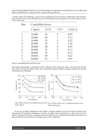
transfer through the membranes. In terms of maximizing the separation percent, Thigh (55°C), Clow (10,000
ppm), Flow(0.07 mL/s)and Vhigh(9V) table(2) were chosen. Effect of voltage on separation percent at different
feed concentrations and temperatures are depicted in Figs. (6-7). as can be seen, simultaneous increase in
voltage and temperature as well as decrease in feed concentration optimize the separation percent. Fig. (8)
Shows the effect of feed concentration on separation percent at different temperatures. According to this figure,
the same results as above were obtained.
2. Raw water characterization
The proper choice of a desalination technology will depend on the feed water quality, which is mainly
characterized by its total dissolved solids content (TDS value) [9]. Different feed water qualities and their
corresponding salt content are given in Table (3).](https://image.slidesharecdn.com/q5603109116-150803053634-lva1-app6891/85/Desalination-technology-economy-and-simplicity-5-320.jpg)
![Yacoub Yousef Ahmad Alotaibi Int. Journal of Engineering Research and Applications www.ijera.com
ISSN: 2248-9622,Vol. 5, Issue 6, (Part -3) June 2015, pp.109-116
www.ijera.com 114|P a g e
Table 3 feed water characterization by salt content
As an example of a typical seawater composition, Table (4) exemplarily shows characteristic parameters of
Mediterranean seawater [10] for Cyprus and the Canary Islands. Feed water composition varies depending on
local industries’ discharges, water depth, water temperature, ocean currents, algae growth and many more
parameters.
Table 4 water characterization of feed waterFrom the Mediterranean Sea
2.1. Foulants
Rejected constituents by the RO membrane pose a general fouling risk to plant operation. Foulants can be
classified into four categories [11]
Chemical foulants, which cause scaling](https://image.slidesharecdn.com/q5603109116-150803053634-lva1-app6891/85/Desalination-technology-economy-and-simplicity-6-320.jpg)
![Yacoub Yousef Ahmad Alotaibi Int. Journal of Engineering Research and Applications www.ijera.com
ISSN: 2248-9622,Vol. 5, Issue 6, (Part -3) June 2015, pp.109-116
www.ijera.com 115|P a g e
Dissolved inorganics most likely to cause scaling are Ca ²+, Mg²+, CO3² ̵SO4²̵, silica and iron [12]. If solubility
limits are exceeded, CaCO3, sulphates of calcium, strontium and barium, CaF2and various silica compounds are
the most likely compounds found as scaling on the membrane surface. Hydroxides of Al, Fe and Mn are
normally precipitated before contact with the membrane. Most natural surface and ground waters display high
CaCO3concentrations close to saturation.
Physical foulants or particulate matter, which is related to deposition of particles on the membrane
surface Particulate matter in natural waters, can be classified according to Potts et. al. [10] into four
different categories depending on particle size:
Settable solids > 100 μm
Supra-colloidal solids 1–100 μm
Colloidal solids 0.001–1 μm
Dissolved solids <10 A°
Particles larger than >25 μm can be easily removed by various treatment options such as screens, cartridge
filters, dual-media filters etc.
Biological foulants, which can either deteriorate the membrane or form a biofilm layer, which inhibits
flux across the membrane.
Raw waters contain microorganisms such as bacteria, fungi, algae, viruses and higher organisms such as
protozoa, living or dead, or biotic debris such as bacterial cell wall fragments. At the large membrane surface
dissolved organic nutrients of the water are concentrated due to concentration polarization. Microorganisms
entering a RO system therefore find ideal growth conditions resulting in possible formation of a biofilm
[13].Biofilm formation consists of three stages [14]:
Transport to the membrane surface
Attachment to the surface and
Biofilm growth
Organic foulants, which can interact with the membrane.
Degradation of organic matter such as plants produces a matrix of macromolecules called humic acids. Organics
in natural waters are usually humic substances in concentrations between0.5 and 20 mg/L in BWandupto 100
mg/L in surface seawater TOC [15]. In RO operation it is recommended that humicacids are removed prior to
filter pre-treatment by flocculation, coagulation with hydroxide flocks, ultrafiltration or adsorption on activated
carbon. Other organic foulants in natural waters are oil and grease droplets. A thin fouling layer was observed
by SEMFEG imaging with filamentous organic layer on which some random microorganisms can be seen as
well as some crystals of mineral origin Fig.(9).
Fig. 9. Fouling layer on the membranes of the autopsied module showing (a) organic filamentous deposit and
microorganism and (b) inorganic crystal as imaged by SEM-FEG, magnification 20,000 and 3,500 respectively.](https://image.slidesharecdn.com/q5603109116-150803053634-lva1-app6891/85/Desalination-technology-economy-and-simplicity-7-320.jpg)
![Yacoub Yousef Ahmad Alotaibi Int. Journal of Engineering Research and Applications www.ijera.com
ISSN: 2248-9622,Vol. 5, Issue 6, (Part -3) June 2015, pp.109-116
www.ijera.com 116|P a g e
Conclusion
Solar desalination processes can be devised in
two main types: direct and indirect collection
systems. The “direct method” use solar energy to
produce distillate directly in the solar collector,
whereas in indirect collection systems, two sub-
systems are employed (one for solar energy
collection and the other one for desalination).The
direct solar energy method uses a variety of simple
stills which are appropriate for very small water
demands; indirect methods use thermal or electrical
energy and can be classified as: distillation methods
using solar collectors or membrane methods using
solar collectors and/or photovoltaics for power
generation.
References:
[1] M. Wilf, Fundamentals of RO–NF
technology, International Conference on
Desalination Costing, Limassol, 2004.
[2] Desalination markets 2005–2015, a global
assessment& forecast, Global Water
Intelligence, 2005.
[3] Manolakos, D., Mohamed, E. Sh.,
Karagiannis, I. and Papadakisa, G., 2008.
Technical and economic comparison between
PV-RO system and RO-Solar Rankine
system. Case study: Thirasia Island. 221
(2008) Desalination 221, 37-46.
[4] Water desalination technologies in the
ESCWA member countrieseconomicand
social commission for Western Asia, UN
report,
http://www.escwa.org.ib/information/publicat
ions/division/docs/tech-01-3e.
[5] ARMINES. Technical and economic analysis
of the potential for water desalination in the
Mediterranean region, RENA-CT94–0063,
France; 1996.
[6] Maurel A. Desalination by reverse osmosis
using renewable energies (Solar wind):
cadarache central experiment. In:
Proceedings of the new technologies for the
use of renewable energy sources in water
desalination conference, session II, Athens,
Greece; 1991. p. 17–26.
[7] Avlonitis SA, Kouroumbas K, Vlachakis N.
Energy consumption and membrane
replacement cost for seawater RO
desalination plants. Desalination 2003;
157:151–8.
[8] Thomson M, Gwillim J, Rowbottom A,
Draisey I, Miranda M.
Batterylessphotovoltaic reverse osmosis
desalination system, S/P2/00305/REP, ETSU,
DT1, UK.
[9] Desalination markets 2005–2015, a global
assessment & forecast, Global Water
Intelligence, 2005.
[10] L. Loizides, The cost of environmental and
social sustainability of desalination, Internet
Conference on Desalination Costing,
Limassol, 2004.
[11] D. Hasson, Technion Rabin Desalination
Laboratory, Haifa, Israel, private
conversation.
[12] D.E. Potts, R.C. Ahlert, S.S. Wang, A critical
review of fouling of reverse osmosis
membranes, Desalination, 36 (1981) 235–
264.
[13] J.A. Redondo and I. Lomax, Y2K
generationFILMTEC RO membranes
combined with new pretreatment techniques
to treat raw water with high fouling potential:
summary of experience, Desalination, 136
(2001) 287–306.
[14] M.F.A. Goosen, S.S. Sablani, H. Al-Hinai, S.
Al-Obeidani, R. AL-Belushi and D. Jackson,
Fouling of reverse osmosis and ultrafiltration
membranes: Acritical review, Sep. Sci. Tech.,
39(10) (2004) 2261–2297.
[15] J.A. Redondo and I. Lomax, Experiences
with pretreatment of raw water with high
fouling potential for reverse osmosis plant
using FILMTEC™, membranes,
Desalination, 110 (1997) 167–182.](https://image.slidesharecdn.com/q5603109116-150803053634-lva1-app6891/85/Desalination-technology-economy-and-simplicity-8-320.jpg)

This document discusses various desalination technologies that can be used to remove salt from seawater, including thermal, membrane, and solar-based methods. It focuses on reverse osmosis (RO) and electrodialysis (ED) processes, which are most suitable for small-scale desalination when coupled with solar energy from photovoltaic panels. RO uses pressure to force pretreated water through a semi-permeable membrane, leaving purified water while retaining dissolved salts. ED uses electric current to remove ions from water through ion-exchange membranes. The document analyzes factors that affect the performance of RO and ED, such as water temperature, flow rate, and salt concentration. It also discusses challenges like membrane fou


