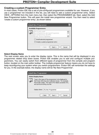
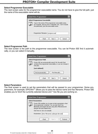
Downloaded 19 times


![PROTON+ Compiler Development Suite
58
Crownhill Associates Limited 2004 - All Rights Reserved Revision 1.2 2004-10-18
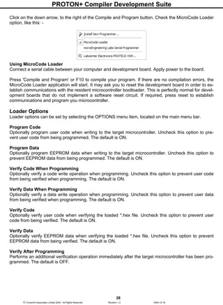
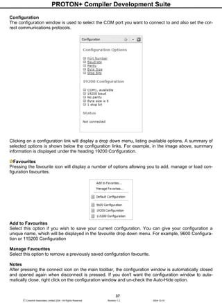
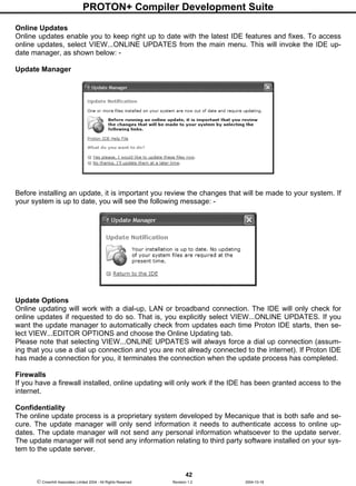
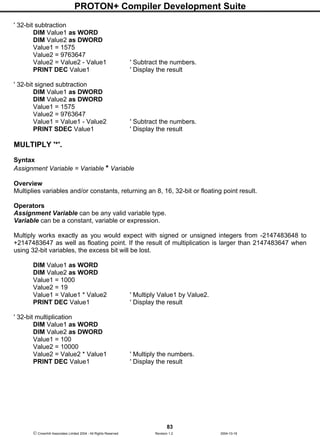
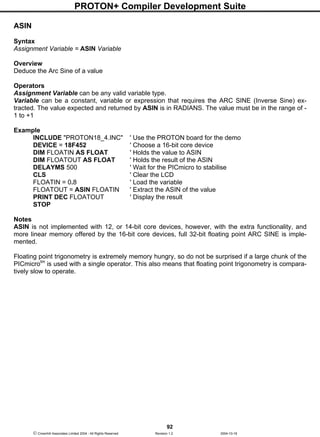
General Format
The compiler is not case sensitive, except when processing string constants such as "hello".
Multiple instructions and labels can be combined on the same line by separating them with colons ':'.
The examples below show the same program as separate lines and as a single-line: -
Multiple-line version: -
TRISB = %00000000 ' Make all pins on PORTB outputs
FOR VAR1 = 0 TO 100 ' Count from 0 to 100
PORTB = VAR1 ' Make PORTB = count (VAR1)
NEXT ' Continue counting until 100 is reached
Single-line version: -
TRISB = %00000000 : FOR VAR1 = 0 TO 100 : PORTB = VAR1 : NEXT
Line Continuation Character '_'
Lines that are too long to display, may be split using the continuation character '_'. This will direct the
continuation of a command to the next line. It's use is only permitted after a comma delimiter: -
VAR1 = LOOKUP VAR2,[1,2,3,_
4,5,6,7,8]
or
PRINT AT 1,1,_
"HELLO WORLD",_
DEC VAR1,_
HEX VAR2](https://image.slidesharecdn.com/protondsuserguide-150604211022-lva1-app6891/85/Proton-ds-userguide-60-320.jpg)
![PROTON+ Compiler Development Suite
59
Crownhill Associates Limited 2004 - All Rights Reserved Revision 1.2 2004-10-18
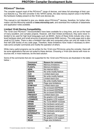
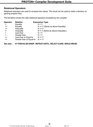
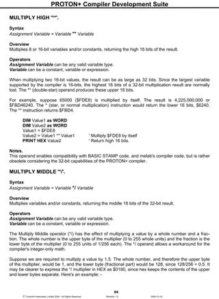
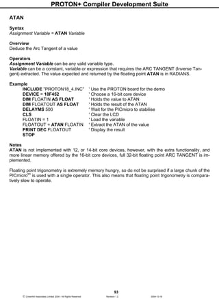
Inline Commands within Comparisons
A very useful addition to the compiler is the ability to mix most INLINE commands into comparisons.
For example: -
ADIN, BUSIN, COUNTER, DIG, EREAD, HBUSIN, INKEY, LCDREAD, LOOKDOWN, LOOK-
DOWNL, LOOKUP, LOOKUPL, PIXEL, POT, PULSIN, RANDOM, SHIN, RCIN, RSIN etc.
All these commands may be used in an IF-THEN, SELECT-CASE, WHILE-WEND, or REPEAT-
UNTIL structure. For example, with the previous versions of the compiler, to read a key using the
INKEY command required a two stage process: -
VAR1 = INKEY
IF VAR1 = 12 THEN { do something }
Now, the structure: -
IF INKEY = 12 THEN { do something }
is perfectly valid. And so is: -
IF ADIN 0 = 1020 THEN { do something } ' Test the ADC from channel 0
The new structure of the in-line commands does not always save code space, however, it does make
the program easier to write, and a lot easier to understand, or debug if things go wrong.
The LOOKUP, LOOKUPL, LOOKDOWN, and LOOKDOWNL commands may also use another in-
line command instead of a variable. For example, to read and re-arrange a key press from a keypad: -
KEY = LOOKUP INKEY, [1,2,3,15,4,5,6,14,7,8,9,13,10,0,11,12,255]
In-line command differences do not stop there. They may now also be used for display purposes in the
RSOUT, SEROUT, HRSOUT, and PRINT commands: -
LABEL: RSOUT LOOKUP INKEY, [1,2,3,15,4,5,6,14,7,8,9,13,10,0,11,12,255] : GOTO LABEL
How's that for a simple serial keypad program. Or: -
WHILE 1 = 1 : PRINT RSIN : WEND
Believe it or not, the above single line of code is a simple serial LCD controller. Accepting serial data
through the RSIN command, and displaying the data with the PRINT command.](https://image.slidesharecdn.com/protondsuserguide-150604211022-lva1-app6891/85/Proton-ds-userguide-61-320.jpg)
![PROTON+ Compiler Development Suite
60
Crownhill Associates Limited 2004 - All Rights Reserved Revision 1.2 2004-10-18
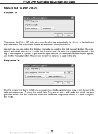
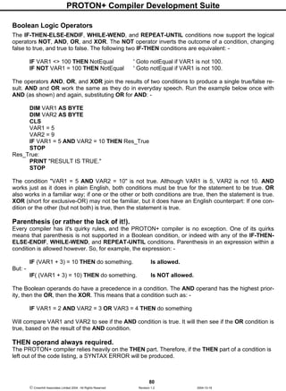
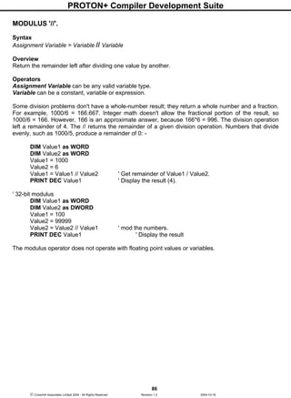
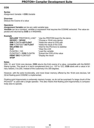
Creating and using Arrays
The PROTON+ compiler supports multi part BYTE, and WORD variables named arrays. An array is a
group of variables of the same size (8-bits wide, or 16-bits wide), sharing a single name, but split into
numbered cells, called elements.
An array is defined using the following syntax: -
DIM Name[ length ] AS BYTE
DIM Name[ length ] AS WORD
where Name is the variable's given name, and the new argument, [ length ], informs the compiler how
many elements you want the array to contain. For example: -
DIM MYARRAY[10] AS BYTE ' Create a 10 element byte array.
DIM MYARRAY[10] AS WORD ' Create a 10 element word array.
A unique feature of the compiler is the ability to allow up to 256 elements within a BYTE array, and
128 elements in a WORD array. However, because of the rather complex way that some PICmicro's
RAM cells are organised (i.e. BANKS), there are a few rules that need to be observed when creating
arrays.
PICmicrotm
Memory Map Complexities.
Larger PICmicros have more RAM available for variable storage, however, accessing the RAM on the
14-bit core devices is not as straightforward as one might expect. The RAM is organised in BANKS,
where each BANK is 128 bytes in length. Crossing these BANKs requires bits 5 and 6 of the STATUS
register to be manipulated. The larger PICmicros such as the 16F877 device have 512 RAM locations,
but only 368 of these are available for variable storage, the rest are known as SYSTEM REGISTERS
and are used to control certain aspects of the PICmicrotm
i.e. TRIS, IO ports, UART etc. The compiler
attempts to make this complex system of BANK switching as transparent to the user as possible, and
succeeds where standard BIT, BYTE, WORD, and DWORD variables are concerned. However, AR-
RAY variables will inevitably need to cross the BANKS in order to create arrays larger than 96 bytes,
which is the largest section of RAM within BANK0. Coincidently, this is also the largest array size per-
missible by most other compilers at the time of writing this manual.
Large arrays (normally over 96 elements) require that their STARTING address be located within the
first 255 bytes of RAM (i.e. within BANK0 and BANK2), the array itself may cross this boundary. This
is easily accomplished by declaring them at, or near the top of the list of variables. The Compiler does
not manipulate the variable declarations. If a variable is placed first in the list, it will be placed in the
first available RAM slot within the PICmicrotm
. This way, you, the programmer maintains finite control
of the variable usage. For example, commonly used variables should be placed near the top of the list
of declared variables. An example of declaring an array is illustrated below: -
DEVICE 16F877 ' Choose a PICmicro with extra RAM
DIM SMALL_ARRAY[20] AS BYTE ' Create a small array of 20 elements
DIM VAR1 AS BYTE ' Create a standard BYTE variable
DIM LARGE_ARRAY[256] AS BYTE ' Create a BYTE array of 256 elements
or
DIM ARRAY1[120] AS BYTE ' Create an array of 120 elements
DIM ARRAY2[100] AS BYTE ' Create another smaller array of 100 elements](https://image.slidesharecdn.com/protondsuserguide-150604211022-lva1-app6891/85/Proton-ds-userguide-62-320.jpg)
![PROTON+ Compiler Development Suite
61
Crownhill Associates Limited 2004 - All Rights Reserved Revision 1.2 2004-10-18
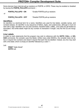
If an array cannot be resolved, then a warning will be issued informing you of the offending line:
WARNING Array ‘array name' is declared at address ‘array address'. Which is over the 255
RAM address limit, and crosses BANK3 boundary!
Ignoring this warning will spell certain failure of your program.
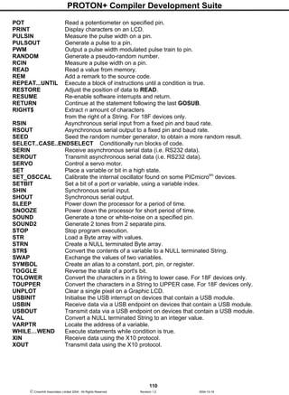
The following array declaration will produce a warning when compiled for a 16F877 device: -
DEVICE 16F877 ' Choose a PICmicro with extra RAM
DIM ARRAY1[200] AS BYTE ' Create an array of 200 elements
DIM ARRAY2[100] AS BYTE ' Create another smaller array of 100 elements
Examining the assembler code produced, will reveal that ARRAY1 starts at address 32 and finishes at
address 295. This is acceptable and the compiler will not complain. Now look at ARRAY2, its start ad-
dress is at 296 which is over the 255 address limit, thus producing a warning message.
The above warning is easily remedied by re-arranging the variable declaration list: -
DIM ARRAY2[100] AS BYTE ' Create a small array of 100 elements
DIM ARRAY1[200] AS BYTE ' Create an array of 200 elements
Again, examining the asm code produced, now reveals that ARRAY2 starts at address 32 and finishes
at address 163. everything OK there then. And ARRAY1 starts at address 164 and finishes at address
427, again, its starting address was within the 255 limit so everything's OK there as well, even though
the array itself crossed several BANKs. A simple re-arrangement of code meant the difference be-
tween a working and not working program.
Of course, the smaller PICmicrotm
devices do not have this limitation as they do not have 255 RAM
cells anyway. Therefore, arrays may be located anywhere in the variable declaration list. The same
goes for the 16-bit core devices, as these can address any area of their RAM.
16-bit core simplicity.
The 16-bit core devices i.e. PIC18XXX, have no such complexities in their memory map as the 14-bit
core devices do. The memory is still banked, but each bank is 256 bytes in length, and runs linearly
from one to the other. Add to that, the ability to access all RAM areas using indirect addressing, makes
arrays extremely easy to use. If many large arrays are required in a program, then the 16-bit core de-
vices (especially the Flash types) are highly recommended.
Once an array is created, its elements may be accessed numerically. Numbering starts at 0 and ends
at n-1. For example: -
MYARRAY [3] = 57
PRINT "MYARRAY[3] = " , DEC MYARRAY[3]
The above example will access the fourth element in the BYTE array and display "MYARRAY[3] = 57"
on the LCD. The true flexibility of arrays is that the index value itself may be a variable. For example: -
DEVICE 16F84 ' We'll use a smaller device this time
DIM MYARRAY[10] AS BYTE ' Create a 10-byte array.
DIM INDEX AS BYTE ' Create a normal BYTE variable.
FOR INDEX = 0 TO 9 ' Repeat with INDEX= 0,1,2...9](https://image.slidesharecdn.com/protondsuserguide-150604211022-lva1-app6891/85/Proton-ds-userguide-63-320.jpg)
![PROTON+ Compiler Development Suite
62
Crownhill Associates Limited 2004 - All Rights Reserved Revision 1.2 2004-10-18
MYARRAY[INDEX] = INDEX * 10 ' Write INDEX*10 to each element of the array.
NEXT
FOR INDEX = 0 TO 9 ' Repeat with INDEX= 0,1,2...9
PRINT AT 1 , 1 , DEC MYARRAY [INDEX] ' Show the contents of each element.
DELAYMS 500 ' Wait long enough to view the values
NEXT
STOP
If the above program is run, 10 values will be displayed, counting from 0 to 90 i.e. INDEX * 10.
A word of caution regarding arrays: If you're familiar with other BASICs and have used their arrays,
you may have run into the "subscript out of range" error. Subscript is simply another term for the index
value. It is considered 'out-of range' when it exceeds the maximum value for the size of the array.
For example, in the example above, MYARRAY is a 10-element array. Allowable index values are 0
through 9. If your program exceeds this range, the compiler will not respond with an error message.
Instead, it will access the next RAM location past the end of the array.
If you are not careful about this, it can cause all sorts of subtle anomalies, as previously loaded vari-
ables are overwritten. It's up to the programmer (you!) to help prevent this from happening.
Even more flexibility is allowed with arrays because the index value may also be an expression.
DEVICE 16F84 ' We'll use a smaller device
DIM MYARRAY[10] AS BYTE ' Create a 10-byte array.
DIM INDEX AS BYTE ' Create a normal BYTE variable.
FOR INDEX = 0 TO 8 ' Repeat with INDEX= 0,1,2...8
MYARRAY[INDEX + 1] = INDEX * 10 ' Write INDEX*10 to each element of the array.
NEXT
FOR INDEX = 0 TO 8 ' Repeat with INDEX= 0,1,2...8
PRINT AT 1 , 1 , DEC MYARRAY [INDEX + 1] ' Show the contents of each element.
DELAYMS 500 ' Wait long enough to view the values
NEXT
STOP
The expression within the square braces should be kept simple, and arrays are not allowed as part of
the expression.
Using Arrays in Expressions.
Of course, arrays are allowed within expressions themselves. For example: -
DIM MYARRAY[10] AS BYTE ' Create a 10-byte array.
DIM INDEX AS BYTE ' Create a normal BYTE variable.
DIM VAR1 AS BYTE ' Create another BYTE variable
DIM Result AS BYTE ' Create a variable to hold the result of the expression
INDEX = 5 ' And INDEX now holds the value 5
VAR1 = 10 ' Variable VAR1 now holds the value 10
MYARRAY[INDEX] = 20 ' Load the 6th
element of MYARRAY with value 20
Result = ( VAR1 * MYARRAY[INDEX] ) / 20 ' Do a simple expression
PRINT AT 1 , 1 , DEC Result , " " ' Display the result of the expression
STOP](https://image.slidesharecdn.com/protondsuserguide-150604211022-lva1-app6891/85/Proton-ds-userguide-64-320.jpg)
![PROTON+ Compiler Development Suite
63
Crownhill Associates Limited 2004 - All Rights Reserved Revision 1.2 2004-10-18
The previous example will display 10 on the LCD, because the expression reads as: -
(10 * 20) / 20
VAR1 holds a value of 10, MYARRAY[INDEX] holds a value of 20, these two variables are multiplied
together which will yield 200, then they're divided by the constant 20 to produce a result of 10.
Arrays as Strings
Arrays may also be used as simple strings in certain commands, because after all, a string is simply a
byte array used to store text.
For this, the STR modifier is used.
The commands that support the STR modifier are: -
BUSOUT - BUSIN
HBUSOUT - HBUSIN (PROTON+ Only)
HRSOUT - HRSIN (PROTON+ Only)
OWRITE - OREAD (PROTON+ Only)
RSOUT - RSIN
SEROUT - SERIN
SHOUT - SHIN
PRINT
The STR modifier works in two ways, it outputs data from a pre-declared array in commands that send
data i.e. RSOUT, PRINT etc, and loads data into an array, in commands that input information i.e.
RSIN, SERIN etc. The following examples illustrate the STR modifier in each compatible command.
Using STR with the BUSIN and BUSOUT commands.
Refer to the sections explaining the BUSIN and BUSOUT commands.
Using STR with the HBUSIN and HBUSOUT commands.
Refer to the sections explaining the HBUSIN and HBUSOUT commands.
Using STR with the RSIN command.
DIM ARRAY1[10] AS BYTE ' Create a 10-byte array named ARRAY1
RSIN STR ARRAY1 ' Load 10 bytes of data directly into ARRAY1
Using STR with the RSOUT command.
DIM ARRAY1[10] AS BYTE ' Create a 10-byte array named ARRAY1
RSOUT STR ARRAY1 ' Send 10 bytes of data directly from ARRAY1
Using STR with the HRSIN and HRSOUT commands.
Refer to the sections explaining the HRSOUT and HRSIN commands.](https://image.slidesharecdn.com/protondsuserguide-150604211022-lva1-app6891/85/Proton-ds-userguide-65-320.jpg)
![PROTON+ Compiler Development Suite
64
Crownhill Associates Limited 2004 - All Rights Reserved Revision 1.2 2004-10-18
Using STR with the SHOUT command.
SYMBOL DTA = PORTA.0 ' Define the two lines for the SHOUT command
SYMBOL CLK = PORTA.1
DIM ARRAY1[10] AS BYTE ' Create a 10-byte array named ARRAY1
' Send 10 bytes of data from ARRAY1
SHOUT DTA, CLK, MSBFIRST, [ STR ARRAY1 ]
Using STR with the SHIN command.
SYMBOL DTA = PORTA.0 ' Define the two lines for the SHIN command
SYMBOL CLK = PORTA.1
DIM ARRAY1[10] AS BYTE ' Create a 10-byte array named ARRAY1
' Load 10 bytes of data directly into ARRAY1
SHIN DTA, CLK, MSBPRE , [ STR ARRAY1 ]
Using STR with the PRINT command.
DIM ARRAY1[10] AS BYTE ' Create a 10-byte array named ARRAY1
PRINT STR ARRAY1 ' Send 10 bytes of data directly from ARRAY1
Using STR with the SEROUT and SERIN commands.
Refer to the sections explaining the SERIN and SEROUT commands.
Using STR with the OREAD and OWRITE commands.
Refer to the sections explaining the OREAD and OWRITE commands.
The STR modifier has two forms for variable-width and fixed-width data, shown below: -
STR bytearray ASCII string from bytearray until byte = 0 (NULL terminated).
Or array length is reached.
STR bytearrayn ASCII string consisting of n bytes from bytearray.
NULL terminated means that a zero (NULL) is placed at the end of the string of ASCII characters to
signal that the string has finished.
The example below is the variable-width form of the STR modifier: -
DIM MYARRAY[5] AS BYTE ' Create a 5 element array
MYARRAY[0] = "A" ' Fill the array with ASCII
MYARRAY[1] = "B"
MYARRAY[2] = "C"
MYARRAY[3] = "D"
MYARRAY[4] = 0 ' Add the NULL Terminator
PRINT STR MYARRAY ' Display the string
The code above displays "ABCD" on the LCD. In this form, the STR formatter displays each character
contained in the byte array until it finds a character that is equal to 0 (value 0, not ASCII "0"). NOTE: If
the byte array does not end with 0 (NULL), the compiler will read and](https://image.slidesharecdn.com/protondsuserguide-150604211022-lva1-app6891/85/Proton-ds-userguide-66-320.jpg)
![PROTON+ Compiler Development Suite
65
Crownhill Associates Limited 2004 - All Rights Reserved Revision 1.2 2004-10-18
output all RAM register contents until it cycles through all RAM locations for the declared length of the
byte array.
For example, the same code as before without a NULL terminator is: -
DIM MYARRAY[4] AS BYTE ' Create a 4 element array
MYARRAY[0] = "A" ' Fill the array with ASCII
MYARRAY[1] = "B"
MYARRAY[2] = "C"
MYARRAY[3] = "D"
PRINT STR MYARRAY ' Display the string
The code above will display the whole of the array, because the array was declared with only four ele-
ments, and each element was filled with an ASCII character i.e. "ABCD".
To specify a fixed-width format for the STR modifier, use the form STR MYARRAYn; where MYAR-
RAY is the byte array and n is the number of characters to display, or transmit. Changing the PRINT
line in the examples above to: -
PRINT STR MYARRAY 2
would display "AB" on the LCD.
STR is not only used as a modifier, it is also a command, and is used for initially filling an array with
data. The above examples may be re-written as: -
DIM MYARRAY[5] AS BYTE ' Create a 5 element array
STR MYARRAY = "ABCD" , 0 ' Fill the array with ASCII, and NULL terminate it
PRINT STR MYARRAY ' Display the string
Strings may also be copied into other strings: -
DIM String1[5] AS BYTE ' Create a 5 element array
DIM String2[5] AS BYTE ' Create another 5 element array
STR String1 = "ABCD" , 0 ' Fill the array with ASCII, and NULL terminate it
STR String2 = "EFGH" , 0 ' Fill the other array with ASCII, and NULL terminate it
STR String1 = STR String2 ' Copy String2 into String1
PRINT STR String1 ' Display the string
The above example will display "EFGH", because String1 has been overwritten by String2.
Using the STR command with BUSOUT, HBUSOUT, SHOUT, and OWRITE differs from using it with
commands SEROUT, PRINT, HRSOUT, and RSOUT in that, the latter commands are used more for
dealing with text, or ASCII data, therefore these are NULL terminated.
The HBUSOUT, BUSOUT, SHOUT, and OWRITE commands are not commonly used for sending
ASCII data, and are more inclined to send standard 8-bit bytes. Thus, a NULL terminator would cut
short a string of byte data, if one of the values happened to be a 0. So these commands will output
data until the length of the array is reached, or a fixed length terminator is used i.e. MYARRAYn.](https://image.slidesharecdn.com/protondsuserguide-150604211022-lva1-app6891/85/Proton-ds-userguide-67-320.jpg)
![PROTON+ Compiler Development Suite
70
Crownhill Associates Limited 2004 - All Rights Reserved Revision 1.2 2004-10-18
Slicing a STRING into pieces.
Each position within the string can be accessed the same as a BYTE ARRAY by using square braces:
-
DEVICE = 18F452 ' Must be a 16-bit core device for Strings
DIM SOURCE_STRING as STRING * 20 ' Create a String
SOURCE_STRING[0] = "H" ' Place the letter "H" as the first character in the string
SOURCE_STRING[1] = "E" ' Place the letter "E" as the second character
SOURCE_STRING[2] = "L" ' Place the letter "L" as the third character
SOURCE_STRING[3] = "L" ' Place the letter "L" as the fourth character
SOURCE_STRING[4] = "O" ' Place the letter "O" as the fifth character
SOURCE_STRING[5] = 0 ' Add a NULL to terminate the string
PRINT SOURCE_STRING ' Display the string, which will be "HELLO"
STOP
The example above demonstrates the ability to place individual characters anywhere in the string. Of
course, you wouldn't use the code above in an actual BASIC program.
A string can also be read character by character by using the same method as shown above: -
DEVICE = 18F452 ' Must be a 16-bit core device for Strings
DIM SOURCE_STRING as STRING * 20 ' Create a String
DIM VAR1 as BYTE
SOURCE_STRING = "HELLO" ' Load the source string with characters
' Copy character 1 from the source string and place it into VAR1
VAR1 = SOURCE_STRING[1]
PRINT VAR1 ' Display the character extracted from the string. Which will be "E"
STOP
When using the above method of reading and writing to a string variable, the first character in the
string is referenced at 0 onwards, just like a BYTE ARRAY.
The example below shows a more practical STRING slicing demonstration.
' Display a string's text by examining each character individually
DEVICE = 18F452 ' Must be a 16-bit core device for Strings
DIM SOURCE_STRING as STRING * 20 ' Create a String
DIM CHARPOS as BYTE ' Holds the position within the string
SOURCE_STRING = "HELLO WORLD" ' Load the source string with characters
CHARPOS = 0 ' Start at position 0 within the string
REPEAT ' Create a loop
' Display the character extracted from the string
PRINT SOURCE_STRING[CHARPOS]
INC CHARPOS ' Move to the next position within the string
' Keep looping until the end of the string is found
UNTIL CHARPOS = LEN (SOURCE_STRING)
STOP](https://image.slidesharecdn.com/protondsuserguide-150604211022-lva1-app6891/85/Proton-ds-userguide-72-320.jpg)
![PROTON+ Compiler Development Suite
77
Crownhill Associates Limited 2004 - All Rights Reserved Revision 1.2 2004-10-18
Line two of the LCD will show EQUAL because STRING2 is then loaded with the text "EGGS" which is
the same as STRING1, therefore the comparison is equal.
A similar example to the one above uses a quoted character string instead of one of the STRING vari-
ables.
Example 2
' String variable to Quoted character string comparison
DEVICE = 18F452 ' Must be a 16-bit core device for Strings
DIM STRING1 as STRING * 20 ' Create a String capable of holding 20 characters
CLS
STRING1 = "EGGS" ' Pre-load String STRING1 with the text EGGS
IF STRING1 = "BACON" THEN ' Is STRING1 equal to "BACON" ?
PRINT AT 1,1, "EQUAL" ' Yes. So display EQUAL on line 1 of the LCD
ELSE ' Otherwise
PRINT AT 1,1, "NOT EQUAL" ' Display NOT EQUAL on line 1 of the LCD
ENDIF
IF STRING1 = "EGGS" THEN ' Is STRING1 equal to "EGGS" ?
PRINT AT 2,1, "EQUAL" ' Yes. So display EQUAL on line 2 of the LCD
ELSE ' Otherwise
PRINT AT 2,1, "NOT EQUAL" ' Display NOT EQUAL on line 2 of the LCD
ENDIF
STOP
The example above produces exactly the same results as example1 because the first comparison is
clearly not equal, while the second comparison is equal.
Example 3
' Use a string comparison in a REPEAT-UNTIL loop
DEVICE = 18F452 ' Must be a 16-bit core device for Strings
DIM SOURCE_STRING as STRING * 20 ' Create a String
DIM DEST_STRING as STRING * 20 ' Create another String
DIM CHARPOS as Byte ' Character position within the strings
CLS
CLEAR DEST_STRING ' Fill DEST_STRING with NULLs
SOURCE_STRING = "HELLO" ' Load String SOURCE_STRING with the text HELLO
REPEAT ' Create a loop
' Copy SOURCE_STRING into DEST_STRING one character at a time
DEST_STRING[CHARPOS] = SOURCE_STRING[CHARPOS]
INC CHARPOS ' Move to the next character in the strings
' Stop when DEST_STRING is equal to the text "HELLO"
UNTIL DEST_STRING = "HELLO"
PRINT DEST_STRING ' Display DEST_STRING
STOP](https://image.slidesharecdn.com/protondsuserguide-150604211022-lva1-app6891/85/Proton-ds-userguide-79-320.jpg)
![PROTON+ Compiler Development Suite
85
Crownhill Associates Limited 2004 - All Rights Reserved Revision 1.2 2004-10-18
DIM Value1 as WORD
Value1 = 100
Value1 = Value1 */ $0180 ' Multiply by 1.5 [1 + (128/256)]
PRINT DEC Value1 ' Display result (150).
To calculate constants for use with the */ instruction, put the whole number portion in the upper byte,
then use the following formula for the value of the lower byte: -
INT(fraction * 256)
For example, take Pi (3.14159). The upper byte would be $03 (the whole number), and the lower
would be INT(0.14159 * 256) = 36 ($24). So the constant Pi for use with */ would be $0324. This isn't a
perfect match for Pi, but the error is only about 0.1%.
Notes.
This operand enables compatibility with BASIC STAMP code, and melab's compiler code, but is rather
obsolete considering the 32-bit capabilities of the PROTON+ compiler.
DIVIDE '/'.
Syntax
Assignment Variable = Variable / Variable
Overview
Divides variables and/or constants, returning an 8, 16, 32-bit or floating point result.
Operators
Assignment Variable can be any valid variable type.
Variable can be a constant, variable or expression.
The Divide operator (/) works exactly as you would expect with signed or unsigned integers from -
2147483648 to +2147483647 as well as floating point.
DIM Value1 as WORD
DIM Value2 as WORD
Value1 = 1000
Value2 = 5
Value1 = Value1 / Value2 ' Divide the numbers.
PRINT DEC Value1 ' Display the result (200).
' 32-bit division
DIM Value1 as WORD
DIM Value2 as DWORD
Value1 = 100
Value2 = 10000
Value2 = Value2 / Value1 ' Divide the numbers.
PRINT DEC Value1 ' Display the result](https://image.slidesharecdn.com/protondsuserguide-150604211022-lva1-app6891/85/Proton-ds-userguide-87-320.jpg)
![PROTON+ Compiler Development Suite
109
Crownhill Associates Limited 2004 - All Rights Reserved Revision 1.2 2004-10-18
HBUSOUT Write to an I2
C device using the MSSP module.
HIGH Make a pin or port high.
HPWM Generate a PWM signal using the CCP module.
HRSIN Receive data from the serial port on devices that contain a USART.
HRSOUT Transmit data from the serial port on devices that contain a USART.
HSERIN Receive data from the serial port on devices that contain a USART.
HSEROUT Transmit data from the serial port on devices that contain a USART.
HRSIN2 Same as HRSIN but using a 2nd USART if available.
HRSOUT2 Same as HRSOUT but using a 2nd USART if available.
HSERIN2 Same as HSERIN but using a 2nd USART if available.
HSEROUT2 Same as HSEROUT but using a 2nd USART if available.
IF..THEN..ELSEIF..ELSE..ENDIF Conditionally execute statements.
INC Increment a variable.
INCLUDE Load a BASIC file into the source code.
INKEY Scan a keypad.
INPUT Make pin an input.
[LET] Assign the result of an expression to a variable. (Optional command).
LCDREAD Read a single byte from a Graphic LCD.
LCDWRITE Write bytes to a Graphic LCD.
LEFT$ Extract n amount of characters
from the left of a String. For 18F devices only.
LDATA Place information into code memory. For access by LREAD.
LINE Draw a line in any direction on a graphic LCD.
LINETO Draw a straight line in any direction on a graphic LCD, starting from the
previous LINE command's end position.
LOADBIT Set or Clear a bit of a port or variable, using a variable index.
LOOKDOWN Search a constant lookdown table for a value.
LOOKDOWNL Search constant or variable lookdown table for a value.
LOOKUP Fetch a constant value from a lookup table.
LOOKUPL Fetch a constant or variable value from lookup table.
LOW Make a pin or port low.
LREAD Read a value from an LDATA table and place into Variable.
LREAD8, LREAD16, LREAD32 Read a single or multi-byte value from an LDATA table with
more efficiency than LREAD.
MID$ Extract n amount of characters from a String beginning at n characters
from the left. For 18F devices only.
ON INTERRUPT Execute a subroutine using a SOFTWARE interrupt.
ON_INTERRUPT Execute an ASSEMBLER subroutine on a HARWARE interrupt.
ON_LOW_INTERRUPT Execute an ASSEMBLER subroutine when a LOW PRIORITY
HARDWARE interrupt occurs on a 16-bit core device.
ON GOSUB Call a Subroutine based on an Index value. For 18F devices only.
ON GOTO Jump to an address in code memory based on an Index value.
(Primarily for smaller PICmicros)
ON GOTOL Jump to an address in code memory based on an Index value.
(Primarily for larger PICmicros)
OUTPUT Make a pin an output.
OREAD Receive data from a device using the Dallas 1-wire protocol.
OWRITE Send data to a device using the Dallas 1-wire protocol.
ORG Set Program Origin.
PEEK Read a byte from a register or variable. Rarely used, now obsolete.
PIXEL Read a single pixel from a Graphic LCD.
PLOT Set a single pixel on a Graphic LCD.
POKE Write a byte to register or variable. Rarely used, now obsolete, command.](https://image.slidesharecdn.com/protondsuserguide-150604211022-lva1-app6891/85/Proton-ds-userguide-111-320.jpg)
![PROTON+ Compiler Development Suite
115
Crownhill Associates Limited 2004 - All Rights Reserved Revision 1.2 2004-10-18
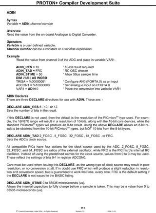
BRANCH
Syntax
BRANCH Index, [Label1 {,...Labeln }]
Overview
Cause the program to jump to different locations based on a variable index. On a PICmicrotm
device
with only one page of memory.
Operators
Index is a constant, variable, or expression, that specifies the address to branch to.
Label1,...Labeln are valid labels that specify where to branch to. A maximum of 255 labels may be
placed between the square brackets, 256 if using a 16-bit core device.
Example
DEVICE 16F84
DIM INDEX AS BYTE
Start: INDEX = 2 ' Assign INDEX a value of 2
' Jump to label 2 (Lab_2) because INDEX = 2
BRANCH INDEX,[Lab_0, Lab_1, Lab_2]
Lab_0: INDEX = 2 ' INDEX now equals 2
GOTO Start
Lab_1: INDEX = 0 ' INDEX now equals 0
GOTO Start
Lab_2: INDEX = 1 ' INDEX now equals 1
GOTO Start
The above example we first assign the index variable a value of 2, then we define our labels. Since the
first position is considered 0 and the variable index equals 2 the BRANCH command will cause the
program to jump to the third label in the brackets [Lab_2].
Notes
BRANCH operates the same as ON x GOTO. It's useful when you want to organise a structure such
as: -
IF VAR1 = 0 THEN GOTO Lab_0 ' VAR1 =0: go to label "Lab_0"
IF VAR1 = 1 THEN GOTO Lab_1 ' VAR1 =1: go to label "Lab_1"
IF VAR1 = 2 THEN GOTO Lab_2 ' VAR1 =2: go to label "Lab_2"
You can use BRANCH to organise this into a single statement: -
BRANCH VAR1, [Lab_0 , Lab_1, Lab_2]
This works exactly the same as the above IF...THEN example. If the value is not in range (in this case
if VAR1 is greater than 2), BRANCH does nothing. The program continues with the next instruction..
The BRANCH command is primarily for use with PICmicrotm
devices that have one page of memory
(0-2047). If larger PICmicro's are used and you suspect that the branch label will be over a page
boundary, use the BRANCHL command instead.
See also : BRANCHL](https://image.slidesharecdn.com/protondsuserguide-150604211022-lva1-app6891/85/Proton-ds-userguide-117-320.jpg)
![PROTON+ Compiler Development Suite
116
Crownhill Associates Limited 2004 - All Rights Reserved Revision 1.2 2004-10-18
BRANCHL
Syntax
BRANCHL Index, [Label1 {,...Labeln }]
Overview
Cause the program to jump to different locations based on a variable index. On a PICmicrotm
device
with more than one page of memory.
Operators
Index is a constant, variable, or expression, that specifies the address to branch to.
Label1,...Labeln are valid labels that specify where to branch to. A maximum of 127 labels may be
placed between the square brackets, 256 if using a 16-bit core device.
Example
DEVICE 16F877
DIM INDEX AS BYTE
Start: INDEX = 2 ' Assign INDEX a value of 2
' Jump to label 2 (Lab_2) because INDEX = 2
BRANCHL INDEX,[Lab_0, Lab_1, Lab_2]
Lab_0: INDEX = 2 ' INDEX now equals 2
GOTO Start
Lab_1: INDEX = 0 ' INDEX now equals 0
GOTO Start
Lab_2: INDEX = 1 ' INDEX now equals 1
GOTO Start
The above example we first assign the index variable a value of 2, then we define our labels. Since the
first position is considered 0 and the variable index equals 2 the BRANCHL command will cause the
program to jump to the third label in the brackets [Lab_2].
Notes
The BRANCHL command is mainly for use with PICmicrotm
devices that have more than one page of
memory (greater than 2048). It may also be used on any PICmicrotm
device, but does produce code
that is larger than BRANCH.
See also : BRANCH](https://image.slidesharecdn.com/protondsuserguide-150604211022-lva1-app6891/85/Proton-ds-userguide-118-320.jpg)
![PROTON+ Compiler Development Suite
119
Crownhill Associates Limited 2004 - All Rights Reserved Revision 1.2 2004-10-18
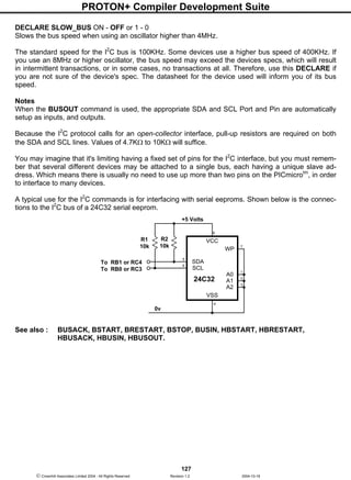
BSTART
Syntax
BSTART
Overview
Send a START condition to the I2
C bus.
Notes
Because of the subtleties involved in interfacing to some I2
C devices, the compiler's standard BUSIN,
and BUSOUT commands were found lacking somewhat. Therefore, individual pieces of the I2
C proto-
col may be used in association with the new structure of BUSIN, and BUSOUT. See relevant sections
for more information.
Example
' Interface to a 24LC32 serial eeprom
DEVICE = 16F877
DIM Loop AS BYTE
DIM Array[10] AS BYTE
' Transmit bytes to the I2C bus
BSTART ' Send a START condition
BUSOUT %10100000 ' Target an eeprom, and send a WRITE command
BUSOUT 0 ' Send the HIGHBYTE of the address
BUSOUT 0 ' Send the LOWBYTE of the address
FOR LOOP = 48 TO 57 ' Create a loop containing ASCII 0 to 9
BUSOUT LOOP ' Send the value of LOOP to the eeprom
NEXT ' Close the loop
BSTOP ' Send a STOP condition
DELAYMS 10 ' Wait for the data to be entered into eeprom matrix
' Receive bytes from the I2C bus
BSTART ' Send a START condition
BUSOUT %10100000 ' Target an eeprom, and send a WRITE command
BUSOUT 0 ' Send the HIGHBYTE of the address
BUSOUT 0 ' Send the LOWBYTE of the address
BRESTART ' Send a RESTART condition
BUSOUT %10100001 ' Target an eeprom, and send a READ command
FOR Loop = 0 TO 9 ' Create a loop
Array[Loop] = BUSIN ' Load an array with bytes received
IF Loop = 9 THEN BSTOP : ELSE BUSACK ' ACK or STOP ?
NEXT ' Close the loop
PRINT AT 1,1, STR Array ' Display the Array as a STRING
STOP
See also: BSTOP, BRESTART, BUSACK, BUSIN, BUSOUT, HBSTART, HBRESTART, HBU-
SACK, HBUSIN, HBUSOUT.](https://image.slidesharecdn.com/protondsuserguide-150604211022-lva1-app6891/85/Proton-ds-userguide-121-320.jpg)
![PROTON+ Compiler Development Suite
121
Crownhill Associates Limited 2004 - All Rights Reserved Revision 1.2 2004-10-18
BUSIN
Syntax
Variable = BUSIN Control , { Address }
or
Variable = BUSIN
or
BUSIN Control , { Address }, [ Variable {, Variable…} ]
or
BUSIN Variable
Overview
Receives a value from the I2
C bus, and places it into variable/s. If structures TWO or FOUR (see
above) are used, then NO ACKNOWLEDGE, or STOP is sent after the data. Structures ONE and
THREE first send the control and optional address out of the clock pin (SCL), and data pin (SDA).
Operators
Variable is a user defined variable or constant.
Control may be a constant value or a BYTE sized variable expression.
Address may be a constant value or a variable expression.
The four variations of the BUSIN command may be used in the same BASIC program. The SECOND
and FOURTH types are useful for simply receiving a single byte from the bus, and must be used in
conjunction with one of the low level commands. i.e. BSTART, BRESTART, BUSACK, or BSTOP. The
FIRST, and THIRD types may be used to receive several values and designate each to a separate
variable, or variable type.
The BUSIN command operates as an I2
C master, using the PICmicro's MSSP module, and may be
used to interface with any device that complies with the 2-wire I2
C protocol.
The most significant 7-bits of control byte contain the control code and the slave address of the device
being interfaced with. Bit-0 is the flag that indicates whether a read or write command is being imple-
mented.
For example, if we were interfacing to an external eeprom such as the 24C32, the control code would
be %10100001 or $A1. The most significant 4-bits (1010) are the eeprom's unique slave address. Bits
2 to 3 reflect the three address pins of the eeprom. And bit-0 is set to signify that we wish to read from
the eeprom. Note that this bit is automatically set by the BUSIN command, regardless of its initial set-
ting.
Example
' Receive a byte from the I2
C bus and place it into variable VAR1.
DIM VAR1 AS BYTE ' We'll only read 8-bits
DIM ADDRESS AS WORD ' 16-bit address required
SYMBOL Control %10100001 ' Target an eeprom](https://image.slidesharecdn.com/protondsuserguide-150604211022-lva1-app6891/85/Proton-ds-userguide-123-320.jpg)
![PROTON+ Compiler Development Suite
122
Crownhill Associates Limited 2004 - All Rights Reserved Revision 1.2 2004-10-18
ADDRESS = 20 ' Read the value at address 20
VAR1 = BUSIN Control , ADDRESS ' Read the byte from the eeprom
or
BUSIN Control , ADDRESS, [ VAR1 ] ' Read the byte from the eeprom
Address, is an optional parameter that may be an 8-bit or 16-bit value. If a variable is used in this po-
sition, the size of address is dictated by the size of the variable used (BYTE or WORD). In the case of
the previous eeprom interfacing, the 24C32 eeprom requires a 16-bit address. While the smaller types
require an 8-bit address. Make sure you assign the right size address for the device interfaced with, or
you may not achieve the results you intended.
The value received from the bus depends on the size of the variables used, except for variation three,
which only receives a BYTE (8-bits). For example: -
DIM WRD AS WORD ' Declare a WORD size variable
WRD = BUSIN Control , Address
Will receive a 16-bit value from the bus. While: -
DIM VAR1 AS BYTE ' Declare a BYTE size variable
VAR1 = BUSIN Control , Address
Will receive an 8-bit value from the bus.
Using the THIRD variation of the BUSIN command allows differing variable assignments. For exam-
ple: -
DIM VAR1 AS BYTE
DIM WRD AS WORD
BUSIN Control , Address , [ VAR1 , WRD ]
Will receive two values from the bus, the first being an 8-bit value dictated by the size of variable
VAR1 which has been declared as a byte. And a 16-bit value, this time dictated by the size of the vari-
able WRD which has been declared as a word. Of course, BIT type variables may also be used, but in
most cases these are not of any practical use as they still take up a byte within the eeprom.
The SECOND and FOURTH variations allow all the subtleties of the I2
C protocol to be exploited, as
each operation may be broken down into its constituent parts. It is advisable to refer to the datasheet
of the device being interfaced to fully understand its requirements. See section on BSTART,
BRESTART, BUSACK, or BSTOP, for example code.
Declares
See BUSOUT for declare explanations.
Notes
When the BUSOUT command is used, the appropriate SDA and SCL Port and Pin are automatically
setup as inputs, and outputs.
Because the I2
C protocol calls for an open-collector interface, pull-up resistors are required on both
the SDA and SCL lines. Values of 4.7KΩ to 10KΩwill suffice.](https://image.slidesharecdn.com/protondsuserguide-150604211022-lva1-app6891/85/Proton-ds-userguide-124-320.jpg)
![PROTON+ Compiler Development Suite
123
Crownhill Associates Limited 2004 - All Rights Reserved Revision 1.2 2004-10-18
You may imagine that it's limiting having a fixed set of pins for the I2
C interface, but you must remem-
ber that several different devices may be attached to a single bus, each having a unique slave ad-
dress. Which means there is usually no need to use up more than two pins on the PICmicrotm
, in order
to interface to many devices.
STR modifier with BUSIN
Using the STR modifier allows variations THREE and FOUR of the BUSIN command to transfer the
bytes received from the I2
C bus directly into a byte array. If the amount of received characters is not
enough to fill the entire array, then a formatter may be placed after the array's name, which will only
receive characters until the specified length is reached. An example of each is shown below: -
DIM Array[10] AS BYTE ' Define an array of 10 bytes
DIM Address AS BYTE ' Create a word sized variable
BUSIN %10100000 , Address , [ STR Array] ' Load data into all the array
' Load data into only the first 5 elements of the array
BUSIN %10100000 , Address , [ STR Array5]
BSTART ' Send a START condition
BUSOUT %10100000 ' Target an eeprom, and send a WRITE command
BUSOUT 0 ' Send the HIGHBYTE of the address
BUSOUT 0 ' Send the LOWBYTE of the address
BRESTART ' Send a RESTART condition
BUSOUT %10100001 ' Target an eeprom, and send a READ command
BUSIN STR Array ' Load all the array with bytes received
BSTOP ' Send a STOP condition
An alternative ending to the above example is: -
BUSIN STR Array5 ' Load data into only the first 5 elements of the array
BSTOP ' Send a STOP condition
See also : BUSACK, BSTART, BRESTART, BSTOP, BUSOUT, HBSTART, HBRESTART,
HBUSACK, HBUSIN, HBUSOUT.](https://image.slidesharecdn.com/protondsuserguide-150604211022-lva1-app6891/85/Proton-ds-userguide-125-320.jpg)
![PROTON+ Compiler Development Suite
124
Crownhill Associates Limited 2004 - All Rights Reserved Revision 1.2 2004-10-18
BUSOUT
Syntax
BUSOUT Control , { Address } , [ Variable {, Variable…} ]
or
BUSOUT Variable
Overview
Transmit a value to the I2
C bus, by first sending the control and optional address out of the clock pin
(SCL), and data pin (SDA). Or alternatively, if only one operator is included after the BUSOUT com-
mand, a single value will be transmitted, along with an ACK reception.
Operators
Variable is a user defined variable or constant.
Control may be a constant value or a BYTE sized variable expression.
Address may be a constant, variable, or expression.
The BUSOUT command operates as an I2
C master and may be used to interface with any device that
complies with the 2-wire I2
C protocol.
The most significant 7-bits of control byte contain the control code and the slave address of the device
being interfaced with. Bit-0 is the flag that indicates whether a read or write command is being imple-
mented.
For example, if we were interfacing to an external eeprom such as the 24C32, the control code would
be %10100000 or $A0. The most significant 4-bits (1010) are the eeprom's unique slave address. Bits
2 to 3 reflect the three address pins of the eeprom. And Bit-0 is clear to signify that we wish to write to
the eeprom. Note that this bit is automatically cleared by the BUSOUT command, regardless of its ini-
tial value.
Example
' Send a byte to the I2
C bus.
DIM VAR1 AS BYTE ' We'll only read 8-bits
DIM Address AS WORD ' 16-bit address required
SYMBOL Control = %10100000 ' Target an eeprom
Address = 20 ' Write to address 20
VAR1 = 200 ' The value place into address 20
BUSOUT Control , Address , [ VAR1 ] ' Send the byte to the eeprom
DELAYMS 10 ' Allow time for allocation of byte
Address, is an optional parameter that may be an 8-bit or 16-bit value. If a variable is used in this po-
sition, the size of address is dictated by the size of the variable used (BYTE or WORD). In the case of
the above eeprom interfacing, the 24C32 eeprom requires a 16-bit address. While the smaller types
require an 8-bit address. Make sure you assign the right size address for the device interfaced with, or
you may not achieve the results you intended.](https://image.slidesharecdn.com/protondsuserguide-150604211022-lva1-app6891/85/Proton-ds-userguide-126-320.jpg)
![PROTON+ Compiler Development Suite
125
Crownhill Associates Limited 2004 - All Rights Reserved Revision 1.2 2004-10-18
The value sent to the bus depends on the size of the variables used. For example: -
DIM WRD AS WORD ' Declare a WORD size variable
BUSOUT Control , Address , [ WRD ]
Will send a 16-bit value to the bus. While: -
DIM VAR1 AS BYTE ' Declare a BYTE size variable
BUSOUT Control , Address , [ VAR1 ]
Will send an 8-bit value to the bus.
Using more than one variable within the brackets allows differing variable sizes to be sent. For exam-
ple: -
DIM VAR1 AS BYTE
DIM WRD AS WORD
BUSOUT Control , Address , [ VAR1 , WRD ]
Will send two values to the bus, the first being an 8-bit value dictated by the size of variable VAR1
which has been declared as a byte. And a 16-bit value, this time dictated by the size of the variable
WRD which has been declared as a word. Of course, BIT type variables may also be used, but in
most cases these are not of any practical use as they still take up a byte within the eeprom.
A string of characters can also be transmitted, by enclosing them in quotes: -
BUSOUT Control , Address , [ "Hello World" , VAR1 , WRD ]
Using the second variation of the BUSOUT command, necessitates using the low level commands i.e.
BSTART, BRESTART, BUSACK, or BSTOP.
Using the BUSOUT command with only one value after it, sends a byte of data to the I2
C bus, and re-
turns holding the ACKNOWLEDGE reception. This acknowledge indicates whether the data has been
received by the slave device.
The ACK reception is returned in the PICmicro's CARRY flag, which is STATUS.0, and also SYSTEM
variable PP4.0. A value of zero indicates that the data was received correctly, while a one indicates
that the data was not received, or that the slave device has sent a NACK return. You must read and
understand the datasheet for the device being interfacing to, before the ACK return can be used suc-
cessfully. An code snippet is shown below: -
' Transmit a byte to a 24LC32 serial eeprom
DIM PP4 AS BYTE SYSTEM ‘ Bring the system variable into the BASIC program
BSTART ' Send a START condition
BUSOUT %10100000 ' Target an eeprom, and send a WRITE command
BUSOUT 0 ' Send the HIGHBYTE of the address
BUSOUT 0 ' Send the LOWBYTE of the address
BUSOUT "A" ' Send the value 65 to the bus
IF PP4.0 = 1 THEN GOTO Not_Received ' Has ACK been received OK ?
BSTOP ' Send a STOP condition
DELAYMS 10 ' Wait for the data to be entered into eeprom matrix](https://image.slidesharecdn.com/protondsuserguide-150604211022-lva1-app6891/85/Proton-ds-userguide-127-320.jpg)
![PROTON+ Compiler Development Suite
126
Crownhill Associates Limited 2004 - All Rights Reserved Revision 1.2 2004-10-18
STR modifier with BUSOUT.
The STR modifier is used for transmitting a string of bytes from a byte array variable. A string is a set
of bytes sized values that are arranged or accessed in a certain order. The values 1, 2, 3 would be
stored in a string with the value 1 first, followed by 2 then followed by the value 3. A byte array is a
similar concept to a string; it contains data that is arranged in a certain order. Each of the elements in
an array is the same size. The string 1,2,3 would be stored in a byte array containing three bytes
(elements).
Below is an example that sends four bytes from an array: -
DIM MYARRAY[10] AS BYTE ' Create a 10-byte array.
MYARRAY [0] = "A" ' Load the first 4 bytes of the array
MYARRAY [1] = "B" ' With the data to send
MYARRAY [2] = "C"
MYARRAY [3] = "D"
BUSOUT %10100000 , Address , [ STR MYARRAY 4 ] ' Send 4-byte string.
Note that we use the optional n argument of STR. If we didn't specify this, the program would try to
keep sending characters until all 10 bytes of the array were transmitted. Since we do not wish all 10
bytes to be transmitted, we chose to tell it explicitly to only send the first 4 bytes.
The above example may also be written as: -
DIM MYARRAY [10] AS BYTE ' Create a 10-byte array.
STR MYARRAY = "ABCD" ' Load the first 4 bytes of the array
BSTART ' Send a START condition
BUSOUT %10100000 ' Target an eeprom, and send a WRITE command
BUSOUT 0 ' Send the HIGHBYTE of the address
BUSOUT 0 ' Send the LOWBYTE of the address
BUSOUT STR MYARRAY 4 ' Send 4-byte string.
BSTOP ' Send a STOP condition
The above example, has exactly the same function as the previous one. The only differences are that
the string is now constructed using the STR as a command instead of a modifier, and the low-level
HBUS commands have been used.
Declares
There are three DECLARE directives for use with BUSOUT.
These are: -
DECLARE SDA_PIN PORT . PIN
Declares the port and pin used for the data line (SDA). This may be any valid port on the PICmicrotm
. If
this declare is not issued in the BASIC program, then the default Port and Pin is PORTA.0
DECLARE SCL_PIN PORT . PIN
Declares the port and pin used for the clock line (SCL). This may be any valid port on the PICmicrotm
.
If this declare is not issued in the BASIC program, then the default Port and Pin is PORTA.1
These declares, as is the case with all the DECLARES, may only be issued once in any single pro-
gram, as they setup the I2
C library code at design time.](https://image.slidesharecdn.com/protondsuserguide-150604211022-lva1-app6891/85/Proton-ds-userguide-128-320.jpg)
![PROTON+ Compiler Development Suite
132
Crownhill Associates Limited 2004 - All Rights Reserved Revision 1.2 2004-10-18
The CWRITE command uses the same technique for writing to memory: -
DEVICE 16F877 ' A device with code modifying features
DIM DByte AS BYTE
DIM Loop AS BYTE
' Write a string to FLASH memory at location ADDRESS
CWRITE Address , [ "HELLO WORLD" ]
FOR Loop = 0 TO 9 ' Create a loop of 10
' Read and display memory location ADDRESS + LOOP
PRINT CREAD Address + Loop
NEXT
STOP
' Reserve 10 spaces in FLASH memory
ADDRESS: CDATA 32 , 32 , 32 , 32 , 32 , 32 , 32 , 32 , 32 , 32
Notice the string text now allowed in the CWRITE command. This allows the whole PICmicrotm
to be
used for data storage and retrieval if desired.
Important Note
Take care not to overwrite existing code when using the CWRITE command, and also remember that
the all PICmicrotm
devices have a finite amount of write cycles (approx 1000). A single program can
easily exceed this limit, making that particular memory cell or cells inaccessible.
The configuration fuse setting WRTE must be enabled before CDATA, CREAD and CWRITE may be
used. This enables the self-modifying feature. If the CONFIG directive is used, then the WRTE_ON
fuse setting must be included in the list: -
CONFIG WDT_ON , XT_OSC , WRTE_ON
Because the 14-bit core devices are only capable of holding 14 bits to a WORD, values greater than
16383 ($3FFF) cannot be stored.
16-bit device requirements.
Because the 16-bit core devices are BYTE oriented, as opposed to the 14-bit types which are WORD
oriented. The CDATA tables should contain an even number of values, or corruption may occur on the
last value read. For example: -
EVEN: CDATA 1,2,3,"123"
ODD: CDATA 1,2,3,"12"
Formatting a CDATA table with a 16-bit core device.
Sometimes it is necessary to create a data table with a known format for its values. For example all
values will occupy 4 bytes of data space even though the value itself would only occupy 1 or 2 bytes.
Formatters are not supported with 14-bit core devices, because they can only hold a maximum value
of $3FFF (16383). i.e. 14-bits.
CDATA 100000 , 10000 , 1000 , 100 , 10 , 1
The above line of code would produce an uneven code space usage, as each value requires a differ-
ent amount of code space to hold the values. 100000 would require 4 bytes of code space, 10000 and
1000 would require 2 bytes, but 100, 10, and 1 would only require 1 byte.](https://image.slidesharecdn.com/protondsuserguide-150604211022-lva1-app6891/85/Proton-ds-userguide-134-320.jpg)
![PROTON+ Compiler Development Suite
133
Crownhill Associates Limited 2004 - All Rights Reserved Revision 1.2 2004-10-18
Reading these values using CREAD would cause problems because there is no way of knowing the
amount of bytes to read in order to increment to the next valid value.
The answer is to use formatters to ensure that a value occupies a predetermined amount of bytes.
These are: -
BYTE
WORD
DWORD
FLOAT
Placing one of these formatters before the value in question will force a given length.
CDATA DWORD 100000 , DWORD 10000 , DWORD 1000 ,_
DWORD 100 , DWORD 10 , DWORD 1
BYTE will force the value to occupy one byte of code space, regardless of it's value. Any values above
255 will be truncated to the least significant byte.
WORD will force the value to occupy 2 bytes of code space, regardless of its value. Any values above
65535 will be truncated to the two least significant bytes. Any value below 255 will be padded to bring
the memory count to 2 bytes.
DWORD will force the value to occupy 4 bytes of code space, regardless of its value. Any value below
65535 will be padded to bring the memory count to 4 bytes. The line of code shown above uses the
DWORD formatter to ensure all the values in the CDATA table occupy 4 bytes of code space.
FLOAT will force a value to its floating point equivalent, which always takes up 4 bytes of code space.
If all the values in an CDATA table are required to occupy the same amount of bytes, then a single
formatter will ensure that this happens.
CDATA AS DWORD 100000 , 10000 , 1000 , 100 , 10 , 1
The above line has the same effect as the formatter previous example using separate DWORD for-
matters, in that all values will occupy 4 bytes, regardless of their value. All four formatters can be used
with the AS keyword.
The example below illustrates the formatters in use.
' Convert a DWORD value into a string array
' Using only BASIC commands
' Similar principle to the STR$ command
INCLUDE "PROTON18_4.INC" ' Use a 16-bit core device
DIM P10 AS DWORD ' Power of 10 variable
DIM CNT AS BYTE
DIM J AS BYTE
DIM VALUE AS DWORD ' Value to convert
DIM STRING1[11] AS BYTE ' Holds the converted value](https://image.slidesharecdn.com/protondsuserguide-150604211022-lva1-app6891/85/Proton-ds-userguide-135-320.jpg)
![PROTON+ Compiler Development Suite
134
Crownhill Associates Limited 2004 - All Rights Reserved Revision 1.2 2004-10-18
DIM PTR AS BYTE ' Pointer within the Byte array
DELAYMS 500 ' Wait for PICmicro to stabilise
CLS ' Clear the LCD
CLEAR ' Clear all RAM before we start
VALUE = 1234576 ' Value to convert
GOSUB DWORD_TO_STR ' Convert VALUE to string
PRINT STR STRING1 ' Display the result
STOP
'-------------------------------------------------------------
' Convert a DWORD value into a string array
' Value to convert is placed in 'VALUE'
' Byte array 'STRING1' is built up with the ASCII equivalent
DWORD_TO_STR:
PTR = 0
J = 0
REPEAT
P10 = CREAD DWORD_TBL + (J * 4)
CNT = 0
WHILE VALUE >= P10
VALUE = VALUE - P10
INC CNT
WEND
IF CNT <> 0 THEN
STRING1[PTR] = CNT + "0"
INC PTR
ENDIF
INC J
UNTIL J > 8
STRING1[PTR] = VALUE + "0"
INC PTR
STRING1[PTR] = 0 ' Add the NULL to terminate the string
RETURN
' CDATA table is formatted for all 32 bit values.
' Which means each value will require 4 bytes of code space
DWORD_TBL:
CDATA AS DWORD 1000000000, 100000000, 10000000, 1000000, 100000, 10000, 1000,_
100, 10
Label names as pointers.
If a label's name is used in the list of values in a CDATA table, the labels address will be used. This is
useful for accessing other tables of data using their address from a lookup table. See example below.
Note that this is not always permitted with 14-bit core devices, because they may not be able to hold
the value in a 14-bit word.](https://image.slidesharecdn.com/protondsuserguide-150604211022-lva1-app6891/85/Proton-ds-userguide-136-320.jpg)
![PROTON+ Compiler Development Suite
138
Crownhill Associates Limited 2004 - All Rights Reserved Revision 1.2 2004-10-18
'---------------------------------------------------------------------------------------------------------------------
‘ Main Program Starts Here
Delayms 100
ALL_DIGITAL = True
CF_INIT ' Initialise the CF card's IO lines
While CF_CD1 = 1 : Wend ' Is the Card inserted?
'---------------------------------------------------------------------------------------------------------------------
' WRITE 8-bit values from sector 0 to sector 20
WRITE_CF:
DATA_IO = 0 ‘ Clear the data to write to the card
SECTOR_NUMBER = 0 ‘ Start at sector 0
' Set up the CF card for Writing 1 sector at a time in LBA mode
CF_SECTOR SECTOR_NUMBER,WRITE,1
Repeat ‘ Form a loop for the sectors
BUFFER_SIZE = 0
Hserout ["WRITING SECTOR ",Dec SECTOR_NUMBER,13]
Repeat ‘ Form a loop for bytes in sector
CF_WRITE [DATA_IO] ‘ Write a byte to the CF card
Inc BUFFER_SIZE ‘ Move up a byte
Inc DATA_IO ‘ Increment the data to write
Until BUFFER_SIZE = 512 ‘ Until all bytes are written
Inc SECTOR_NUMBER ' Move up to the next sector
' And Set up the CF card for Writing in LBA mode
CF_SECTOR SECTOR_NUMBER,WRITE
Until SECTOR_NUMBER > 20 ‘ Until all sectors are written
'---------------------------------------------------------------------------------------------------------------------
' READ 8-bit values from sector 0 to sector 20
' And display serially In columns and rows format
READ_CF:
SECTOR_NUMBER = 0 ‘ Start at sector 0
' Set up the CF card for reading 1 sector at a time in LBA mode
CF_SECTOR SECTOR_NUMBER,READ,1
Repeat ‘ Form a loop for the sectors
BUFFER_SIZE = 1
Hserout ["SECTOR ",Dec SECTOR_NUMBER,13]
Repeat ‘ Form a loop for bytes in sector
DATA_IO = CF_READ ‘ Read a byte from the CF card
Hserout [HEX2 DATA_IO," "] ‘ Display it in Hexadecimal
If BUFFER_SIZE // 32 = 0 Then Hserout [13] ‘ Check if row finished
Inc BUFFER_SIZE ‘ Move up a byte
Until BUFFER_SIZE > 512 ‘ Until all bytes are read
Hserout [Rep "-"95,13] ' Draw a line under each sector
Inc SECTOR_NUMBER ' Move up to the next sector
' And set up the CF card for reading in LBA mode
CF_SECTOR SECTOR_NUMBER,READ
Until SECTOR_NUMBER > 20 ‘ Until all sectors are read
Stop](https://image.slidesharecdn.com/protondsuserguide-150604211022-lva1-app6891/85/Proton-ds-userguide-140-320.jpg)
![PROTON+ Compiler Development Suite
139
Crownhill Associates Limited 2004 - All Rights Reserved Revision 1.2 2004-10-18
Example 2
‘ Display a summary of the Compact Flash
Device = 18F452 ‘ We’ll use a 16-bit core device
XTAL = 4
HSERIAL_BAUD = 9600 ' Set baud rate for USART serial coms
HSERIAL_RCSTA = %10010000 ' Enable serial port and continuous receive
HSERIAL_TXSTA = %00100100 ' Enable transmit and asynchronous mode
' CF Card Declarations
CF_DTPORT = PORTD ‘ Assign the CF data port to PORTD
CF_ADPORT = PORTE ‘ Assign the CF address port to PORTE
CF_WEPIN = PORTC.5 ‘ Assign the CF WE pin to PORTC.5
CF_CE1PIN = PORTC.0 ‘ Assign the CF CE1 pin to PORTC.0
CF_RDYPIN = PORTC.4 ‘ Assign the CF RDY_BSY pin to PORTC.4
CF_OEPIN = PORTC.1 ‘ Assign the CF OE pin to PORTC.1
CF_RSTPIN = PORTC.3 ‘ Assign the CF RESET pin to PORTC.3
CF_CD1PIN = PORTA.5 ‘ Assign the CF CD1 pin to PORTA.5
CF_ADPORT_MASK = False ‘ No masking of address data required
CF_READ_WRITE_INLINE = False ‘ Use subroutines for CF_READ/CFWRITE
Symbol CF_CD1 = PORTA.5 ‘ Alias the CD1 pin to PORTA.5
' Variable Declarations
Dim DATA_IO as Word ‘ Words read from CF card
Dim SER_LOOP as Word ‘ Internal counter of bytes
Dim SECTORS_PER_CARD as Dword ‘ The amount of sectors in the CF card
Delayms 100
ALL_DIGITAL = True
CF_INIT ' Initialise the CF card's IO lines
While CF_CD1 = 1 : Wend ' Is the Card inserted?
CF_Write 7,[$EC] ' Write CF execute identify drive command
CF_Write $20,[] ' Set address for READ SECTOR
DATA_IO = CF_Read ‘ Read from the CF card
Hserout ["General configuration = ",Hex4 DATA_IO,13]
DATA_IO = CF_Read ‘ Read from the CF card
Hserout ["Default number of cylinders = ",Dec DATA_IO,13]
DATA_IO = CF_Read ‘ Read from the CF card
Hserout ["Reserved = ",Dec DATA_IO,13]
DATA_IO = CF_Read ‘ Read from the CF card
Hserout ["Default number of heads = ",Dec DATA_IO,13]
DATA_IO = CF_Read ‘ Read from the CF card
Hserout ["Number of unformatted bytes per track = ",Dec DATA_IO,13]
DATA_IO = CF_Read ‘ Read from the CF card
Hserout ["Number of unformatted bytes per sector = ",Dec DATA_IO,13]
DATA_IO = CF_Read ‘ Read from the CF card
Hserout ["Default number of sectors per track = ",Dec DATA_IO,13]
DATA_IO = CF_Read ‘ Read from the CF card
SECTORS_PER_CARD.HighWord = DATA_IO
DATA_IO = CF_Read ‘ Read from the CF card
SECTORS_PER_CARD.LowWord = DATA_IO
Hserout ["Number of sectors per card = ",Dec SECTORS_PER_CARD,13]
DATA_IO = CF_Read ‘ Read from the CF card
Hserout ["Vendor Unique = ",Dec DATA_IO,13]
Hserout ["Serial number in ASCII (Right Justified) = "]](https://image.slidesharecdn.com/protondsuserguide-150604211022-lva1-app6891/85/Proton-ds-userguide-141-320.jpg)
![PROTON+ Compiler Development Suite
140
Crownhill Associates Limited 2004 - All Rights Reserved Revision 1.2 2004-10-18
For SER_LOOP = 0 to 19
DATA_IO.LowByte = CF_Read ‘ Read from the CF card
Hserout [DATA_IO.LowByte]
Next
Hserout [13]
DATA_IO = CF_Read ‘ Read from the CF card
Hserout ["Buffer type = ",Dec DATA_IO,13]
DATA_IO = CF_Read ‘ Read from the CF card
Hserout ["Buffer size in 512 byte increments = ",Dec DATA_IO,13]
DATA_IO = CF_Read ‘ Read from the CF card
Hserout ["# of ECC bytes passed on Read/Write Long Commands = ",_
Dec DATA_IO,13]
Stop
The above example will display on the serial terminal, some details concerning the Compact Flash
card being interfaced. This is ideal for testing if the circuit is working, but is also useful for ascertaining
how many sectors the Compact Flash card contains.
Notes
Accessing a compact flash card is not the same as accessing standard memory. In so much as a
complete sector must be written. i.e. all 512 bytes in a single operation. Reading from a compact flash
card is more conventional in that once the sector is chosen using the CF_SECTOR command, any of
the 512 bytes may be read from that sector.
The compiler’s Compact Flash access commands operate in what is called LBA (Logical Block Ad-
dress) mode. Which means that it is accessed sector by sector instead of the more involved Cylin-
der/Head/Sector mode. LBA mode makes accessing Compact Flash easier and more intuitive. How-
ever, it is important to read and understand the CF+ and Compact Flash specifications document
which can be obtained via the internet at www.compactflash.org.
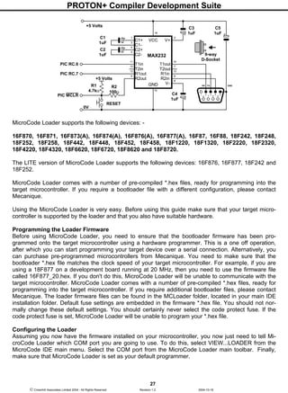
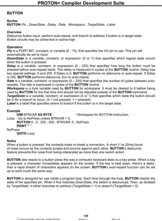
A typical circuit for interfacing a Compact Flash card is shown below: -
C2
0.1uF
5 Volts
A9
VCC
A10
OE
CE1
WE
RDY/BSY
CSEL
GND
13
CF CARD
20
A0
A1
A5
A4
A3
A2
D1
D0
GND
RESET
19
18
17
16
15
14
12
10
8
7
9
36
41
37
32
39
21
1 50
44
D7
D6
D5
D4
D3
D2
CD1
CE2
REG
VCC
38
26
22
23
2
3
4
5
6
11
A6
A7
A8
R1
47k
PORTD.0
PORTD.1
PORTD.2
PORTD.3
PORTD.4
PORTD.5
PORTD.6
PORTD.7
PORTA.5
PORTE.0
PORTE.1
PORTE.2
PORTC.0
PORTC.1
PORTC.3
PORTC.4
PORTC.2
0V
TOPICMICRO](https://image.slidesharecdn.com/protondsuserguide-150604211022-lva1-app6891/85/Proton-ds-userguide-142-320.jpg)
![PROTON+ Compiler Development Suite
143
Crownhill Associates Limited 2004 - All Rights Reserved Revision 1.2 2004-10-18
Repeat ‘ Form a loop for the sectors
BUFFER_SIZE = 1
Hserout ["SECTOR ",Dec SECTOR_NUMBER,13]
Repeat ‘ Form a loop for words in sector
DATA_IO = CF_READ ‘ Read a Word from the CF card
Hserout [HEX4 DATA_IO," "] ‘ Display it in Hexadecimal
If BUFFER_SIZE // 32 = 0 Then Hserout [13] ‘ Check if row finished
Inc BUFFER_SIZE ‘ Move up a word
Until BUFFER_SIZE > 256 ‘ Until all words are read
Hserout [Rep "-"95,13] ' Draw a line under each sector
Inc SECTOR_NUMBER ' Move up to the next sector
' And set up the CF card for reading in LBA mode
CF_SECTOR SECTOR_NUMBER,READ
Until SECTOR_NUMBER > 20 ‘ Until all sectors are read
Stop
Notes
The amount of bytes read from the Compact Card depends on the variable type used as the assign-
ment. i.e. the variable before the equals operator: -
A BIT type variable will read 1 byte from the Compact Flash card.
A BYTE type variable will also read 1 byte from the Compact Flash card.
A WORD type variable will read 2 bytes from the Compact Flash card Least Significant Byte First
(LSB).
A DWORD type variable will read 4 bytes from the Compact Flash card Least Significant Byte First
(LSB).
A FLOAT type variable will also read 4 bytes from the Compact Flash card in the correct format for a
floating point variable.
Accessing Compact Flash memory is not the same as conventional memory. There is no mechanism
for choosing the address of the data in question. You can only choose the sector then sequentially
read the data from the card. In essence, the sector is the equivalent of the address in a conventional
piece of memory, but instead of containing 1 byte of data, it contains 512 bytes.
Once the sector is chosen using the CF_SECTOR command, any amount of the 512 bytes available
can be read from the card. Once a read has been accomplished, the Compact Flash card automati-
cally increments to the next byte in the sector ready for another read. So that a simple loop as shown
below will read all the bytes in a sector: -
BUFFER_SIZE = 0
Repeat ‘ Form a loop for bytes in sector
DATA_IO = CF_READ ‘ Read a Byte from the CF card
Inc BUFFER_SIZE ‘ Increment the byte counter
Until BUFFER_SIZE = 512 ‘ Until all Bytes are read](https://image.slidesharecdn.com/protondsuserguide-150604211022-lva1-app6891/85/Proton-ds-userguide-145-320.jpg)
![PROTON+ Compiler Development Suite
144
Crownhill Associates Limited 2004 - All Rights Reserved Revision 1.2 2004-10-18
In order to extract a specific piece of data from a sector, a similar loop can be used, but with a condi-
tion attached that will drop out at the correct position: -
BUFFER_SIZE = 0
While 1 = 1 ‘ Form an infinite loop
DATA_IO = CF_READ ‘ Read a Byte from the CF card
If BUFFER_SIZE = 20 Then Break ‘ Exit when correct position reached
Inc BUFFER_SIZE ‘ Increment the byte counter
Wend ‘ Close the loop
The snippet above will exit the loop when the 20th
byte has been read from the card.
Of course Arrays can also be loaded from a Compact Flash card in a similar way, but remember, the
maximum size of an array in PROTON BASIC is 256 elements. The snippets below show two possible
methods of loading an array with the data read from a Compact Flash card.
Dim AR1[256] as Byte ‘ Create a 256 element array
Dim BUFFER_SIZE as Word ‘ Internal counter of bytes in sector
BUFFER_SIZE = 0
Repeat ‘ Form a loop for bytes in sector
AR1[BUFFER_SIZE] = CF_READ ‘ Read a Byte from the CF card
Inc BUFFER_SIZE ‘ Increment the byte counter
Until BUFFER_SIZE = 256 ‘ Until all Bytes are read
Large arrays such as the one above are best suited to the 16-bit core devices. Not only because they
generally have more RAM, but because their RAM is accessed more linearly and there are no BANK
boundaries when using arrays. Also, by accessing some low level registers in a 16-bit core device it is
possible to efficiently place all 512 bytes from a sector into 2 arrays:
Device = 18F452 ‘ Choose a 16-bit core device
Dim AR1[256] as Byte ‘ Create a 256 element array
Dim AR2[256] as Byte ‘ Create another 256 element array
Dim BUFFER_SIZE as Word ‘ Internal counter of bytes in sector
Dim FSR0 as FSR0L.Word ‘ Combine FSR0L/H as a 16-bit register
BUFFER_SIZE = 0
FSR0 = Varptr(AR1) ‘ Get the address of AR1 into FSR0L/H
Repeat ‘ Form a loop for bytes in sector
POSTINC0 = CF_READ ‘ Read a Byte from the CF card and place
‘ directly into memory, then increment to
‘ the next address in PIC RAM
Inc BUFFER_SIZE ‘ Increment the byte counter
Until BUFFER_SIZE = 512 ‘ Until all Bytes are read
When the above loop is finished, arrays AR1 and AR2 will hold the data read from the Compact Flash
card’s sector. Of course you will need to pad out the snippets with the appropriate declares and the
CF_SECTOR command.
See Also CF_INIT, CF_SECTOR (for a suitable circuit), CF_WRITE (for declares).](https://image.slidesharecdn.com/protondsuserguide-150604211022-lva1-app6891/85/Proton-ds-userguide-146-320.jpg)
![PROTON+ Compiler Development Suite
145
Crownhill Associates Limited 2004 - All Rights Reserved Revision 1.2 2004-10-18
CF_WRITE
Syntax
CF_WRITE {Address Data} , [ Variable {Variable {, Variable etc}]
Overview
Write data to a Compact Flash card.
Operators
Address Data is an optional value that is placed on the Compact Flash card’s Address lines. This is
not always required when writing to a card.
Variable can be a BIT, BYTE, WORD, DWORD, FLOAT, or STRING type variable that will be written
to the Compact Flash card. More than one variable can be placed between the square braces if more
than one write is required in a single operation.
The variable part of the CF_WRITE command is also optional, as some configurations only require the
card’s address lines to be loaded. In this case, use the syntax: -
CF_WRITE Address Data , [ ]
See example 2 in the CF_SECTOR section for an example of its use.
Example
‘ Write 20 sectors on a compact flash card
Device = 18F452 ‘ We’ll use a 16-bit core device
XTAL = 4
HSERIAL_BAUD = 9600 ' Set baud rate for USART serial coms
HSERIAL_RCSTA = %10010000 ' Enable serial port and continuous receive
HSERIAL_TXSTA = %00100100 ' Enable transmit and asynchronous mode
'---------------------------------------------------------------------------------------------------------------------
' CF Card Declarations
CF_DTPORT = PORTD ‘ Assign the CF data port to PORTD
CF_ADPORT = PORTE ‘ Assign the CF address port to PORTE
CF_WEPIN = PORTC.5 ‘ Assign the CF WE pin to PORTC.5
CF_CE1PIN = PORTC.0 ‘ Assign the CF CE1 pin to PORTC.0
CF_RDYPIN = PORTC.4 ‘ Assign the CF RDY_BSY pin to PORTC.4
CF_OEPIN = PORTC.1 ‘ Assign the CF OE pin to PORTC.1
CF_RSTPIN = PORTC.3 ‘ Assign the CF RESET pin to PORTC.3
CF_CD1PIN = PORTA.5 ‘ Assign the CF CD1 pin to PORTA.5
CF_ADPORT_MASK = False ‘ No masking of address data required
CF_READ_WRITE_INLINE = False ‘ Use subroutines for CF_READ/CFWRITE
Symbol CF_CD1 = PORTA.5 ‘ Alias the CD1 pin to PORTA.5
'---------------------------------------------------------------------------------------------------------------------
' Variable Declarations
Dim DATA_IO as Byte ‘ Bytes written to CF card
Dim BUFFER_SIZE as Word ‘ Internal counter of bytes in sector (i.e.512)
Dim SECTOR_NUMBER as Dword ‘ Sector of interest
'---------------------------------------------------------------------------------------------------------------------
‘ Main Program Starts Here
Delayms 100
ALL_DIGITAL = True](https://image.slidesharecdn.com/protondsuserguide-150604211022-lva1-app6891/85/Proton-ds-userguide-147-320.jpg)
![PROTON+ Compiler Development Suite
146
Crownhill Associates Limited 2004 - All Rights Reserved Revision 1.2 2004-10-18
CF_INIT ' Initialise the CF card's IO lines
While CF_CD1 = 1 : Wend ' Is the Card inserted?
'---------------------------------------------------------------------------------------------------------------------
' WRITE 8-bit values from sector 0 to sector 20
WRITE_CF:
DATA_IO = 0 ‘ Clear the data to write to the card
SECTOR_NUMBER = 0 ‘ Start at sector 0
' Set up the CF card for Writing 1 sector at a time in LBA mode
CF_SECTOR SECTOR_NUMBER,WRITE,1
Repeat ‘ Form a loop for the sectors
BUFFER_SIZE = 0
Hserout ["WRITING SECTOR ",Dec SECTOR_NUMBER,13]
Repeat ‘ Form a loop for bytes in sector
CF_WRITE [DATA_IO] ‘ Write a byte to the CF card
Inc BUFFER_SIZE ‘ Move up a byte
Inc DATA_IO ‘ Increment the data to write
Until BUFFER_SIZE = 512 ‘ Until all bytes are written
Inc SECTOR_NUMBER ' Move up to the next sector
' And Set up the CF card for Writing in LBA mode
CF_SECTOR SECTOR_NUMBER,WRITE
Until SECTOR_NUMBER > 20 ‘ Until all sectors are written
Stop
Notes
The amount of bytes written to the Compact Card depends on the variable type used between the
square braces: -
A BIT type variable will write 1 byte to the Compact Flash card.
A BYTE type variable will also write 1 byte to the Compact Flash card.
A WORD type variable will write 2 bytes to the Compact Flash card Least Significant Byte First (LSB).
A DWORD type variable will write 4 bytes to the Compact Flash card Least Significant Byte First
(LSB).
A FLOAT type variable will also write 4 bytes to the Compact Flash card in the correct format of a
floating point variable.
Accessing Compact Flash memory is not the same as conventional memory. There is no mechanism
for choosing the address of the data in question. You can only choose the sector then sequentially
write the data to the card. In essence, the sector is the equivalent of the address in a conventional
piece of memory, but instead of containing 1 byte of data, it contains 512 bytes.
Once the sector is chosen using the CF_SECTOR command and a write operation is started, all 512
bytes contained in the sector must be written before they are transferred to the card’s flash memory.](https://image.slidesharecdn.com/protondsuserguide-150604211022-lva1-app6891/85/Proton-ds-userguide-148-320.jpg)
![PROTON+ Compiler Development Suite
147
Crownhill Associates Limited 2004 - All Rights Reserved Revision 1.2 2004-10-18
Once a single write has been accomplished, the Compact Flash card automatically increments to the
next byte in the sector ready for another write. So that a simple loop as shown below will write all the
bytes in a sector: -
BUFFER_SIZE = 0
Repeat ‘ Form a loop for bytes in sector
CF_WRITE [DATA_IO] ‘ Write a Byte to the CF card
Inc BUFFER_SIZE ‘ Increment the byte counter
Until BUFFER_SIZE = 512 ‘ Until all Bytes are written
Compact Flash Interface Declares
There are several declares that need to be manipulated when interfacing to a Compact Flash card.
There are the obvious port pins, but there are also some declares that optimise or speed up access to
the card.
DECLARE CF_DTPORT PORT
This declare assigns the Compact Flash card’s data lines. The data line consists of 8-bits so it is only
suitable for ports that contain 8-bits such as PORTB, PORTC, PORTD etc.
DECLARE LCD_ADPORT PORT
This declare assigns the Compact Flash card’s address lines. The address line consists of 3-bits, but
A0 of the compact flash card must be attached to bit-0 of whatever port is used. For example, if the
Compact Flash card’s address lines were attached to PORTA of the PICmicrotm
, then A0 of the CF
card must attach to PORTA.0, A1 or the CF card must attach to PORTA.1, and A2 of the CF card
must attach to PORTA.2.
The CF access commands will mask the data before transferring it to the particular port that is being
used so that the rest of it’s pins are not effected. PORTE is perfect for the address lines as it contains
only 3 pins on a 40-pin device, and the compiler can make full use of this by using the
CF_ADPORT_MASK declare.
DECLARE CF_ADPORT_MASK = ON or OFF, or TRUE or FALSE, or 1, 0
Both the CF_WRITE and CF_SECTOR commands write to the Compact Flash card’s address lines.
However, these only contain 3-bits, so the commands need to ensure that the other bits of the
PICmicro’s PORT are not effected. This is accomplished by masking the unwanted data before trans-
ferring it to the address lines. This takes a little extra code space, and thus a little extra time to accom-
plish. However, there are occasions when the condition of the other bits on the PORT are not impor-
tant, or when a PORT is used that only has 3-bits to it. i.e. PORTE with a 40-pin device. Issuing the
CF_ADPORT_MASK declare and setting it FALSE, will remove the masking mnemonics, thus reduc-
ing code used and time taken.
DECLARE CF_RDYPIN PORT . PIN
Assigns the Compact Flash card’s RDY/BSY line.
DECLARE CF_OEPIN PORT . PIN
Assigns the Compact Flash card’s OE line.
DECLARE CF_WEPIN PORT . PIN
Assigns the Compact Flash card’s WE line.](https://image.slidesharecdn.com/protondsuserguide-150604211022-lva1-app6891/85/Proton-ds-userguide-149-320.jpg)
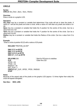
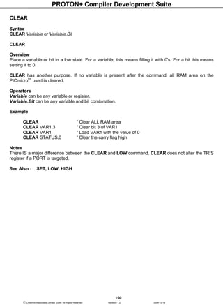
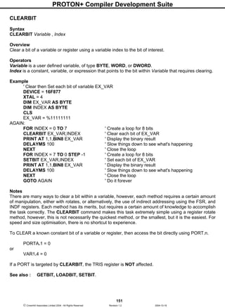
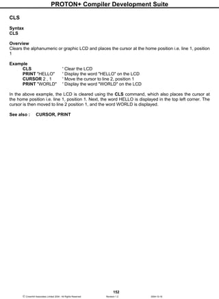
![PROTON+ Compiler Development Suite
157
Crownhill Associates Limited 2004 - All Rights Reserved Revision 1.2 2004-10-18
CWRITE
Syntax
CWRITE Address , [ Variable { , Variable…} ]
Overview
Write data to anywhere in memory.
Operators
Variable can be a constant, variable, or expression.
Address is a constant, variable, label, or expression that represents any valid address within the
PICmicrotm
.
Example
' Write to memory location 2000+ within the PICmicro
DEVICE 16F877 ' Needs to be a 16F87x type PICmicro
DIM VAR1 AS BYTE
DIM WRD AS WORD
DIM Address AS WORD
Address = 2000 ' Address now holds the base address
VAR1 = 234
WRD = 1043
CWRITE Address, [10, VAR1, WRD ] ' Write to address 2000 +
ORG 2000
Notes
The CWRITE command takes advantage of the new self-modifying feature that is available in the
newer 16F87x, and 18 series devices.
If a WORD size variable is used as the assignment, then a 14-bit WORD will be written. If a BYTE
sized variable is used as the assignment, then 8-bits will be written.
Because the 14-bit core devices are only capable of holding 14 bits to a WORD, values greater than
16383 ($3FFF) cannot be written. However, the 16-bit core devices may hold values up to 65535
($FFFF).
The configuration fuse setting WRTE must be enabled before CDATA, CREAD, and CWRITE may be
used, this is the default setting. This enables the self-modifying feature. If the CONFIG directive is
used, then the WRTE_ON fuse setting must be included in the list: -
CONFIG WDT_ON , XT_OSC , WRTE_ON
See also : CDATA, CONFIG, CREAD, ORG.](https://image.slidesharecdn.com/protondsuserguide-150604211022-lva1-app6891/85/Proton-ds-userguide-159-320.jpg)
![PROTON+ Compiler Development Suite
161
Crownhill Associates Limited 2004 - All Rights Reserved Revision 1.2 2004-10-18
DECLARE
Syntax
[DECLARE] code modifying directive = modifying value
Overview
Adjust certain aspects of the produced code, i.e. Crystal frequency, LCD port and pins, serial baud
rate etc.
Operators
code modifying directive is a set of pre-defined words. See list below.
modifying value is the value that corresponds to the command. See list below.
The DECLARE directive is an indispensable part of the compiler. It moulds the library subroutines,
and passes essential user information to them. However, the DECLARE part of a declare directive is
optional.
For example, instead of using: -
DECLARE XTAL 4
The text: -
XTAL = 4
May be used.
Notice that there is an optional equals character separating the declare command and the value to
pass. The structure will still be referred to as a DECLARE in the manual, help file, and any future pro-
jects.
MISC Declares.
DECLARE WATCHDOG = ON or OFF, or TRUE or FALSE, or 1, 0
The WATCHDOG DECLARE directive enables or disables the watchdog timer. It also sets the
PICmicro's CONFIG fuses for no watchdog. In addition, it removes any CLRWDT mnemonics from the
assembled code, thus producing slightly smaller programs. The default for the compiler is WATCH-
DOG OFF, therefore, if the watchdog timer is required, then this DECLARE will need to be invoked.
The WATCHDOG DECLARE can be issued multiple times within the BASIC code, enabling and dis-
abling the watchdog timer as and when required.
DECLARE BOOTLOADER = ON or OFF, or TRUE or FALSE, or 1, 0
The BOOTLOADER DECLARE directive enables or disables the special settings that a serial boot-
loader requires at the start of code space. This directive is ignored if a PICmicrotm
without bootloading
capabilities is targeted.
Disabling the bootloader will free a few bytes from the code produced. This doesn't seem a great deal,
however, these few bytes may be the difference between a working or non-working program. The de-
fault for the compiler is BOOTLOADER ON
DECLARE SHOW_SYSTEM_VARIABLES = ON or OFF, or TRUE or FALSE, or 1, 0](https://image.slidesharecdn.com/protondsuserguide-150604211022-lva1-app6891/85/Proton-ds-userguide-163-320.jpg)
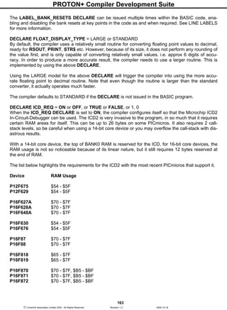
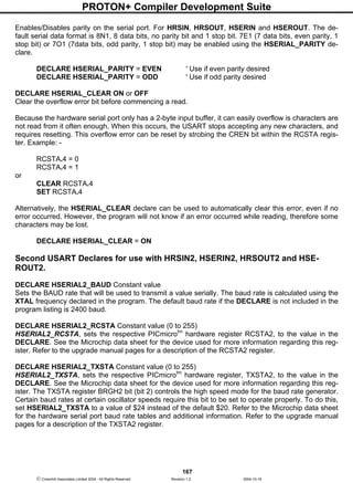
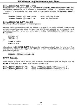
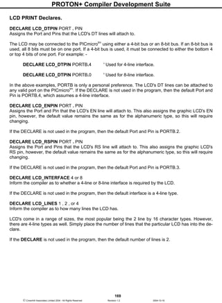
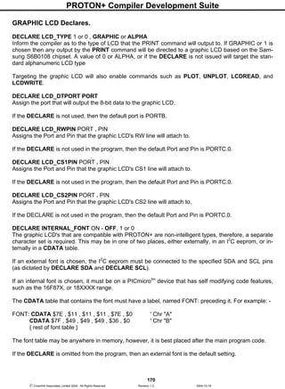

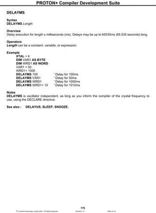
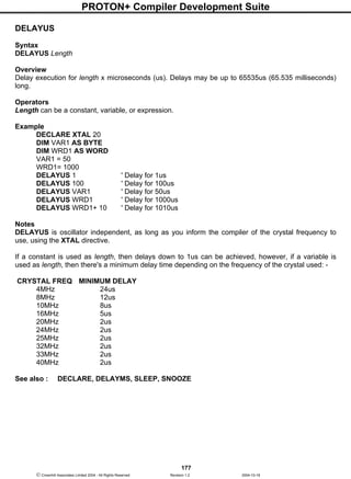
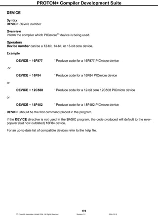
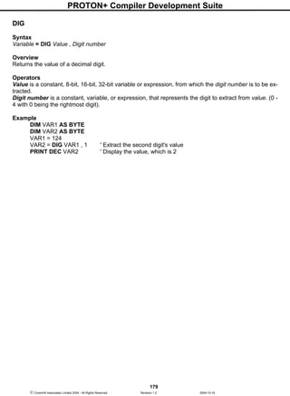
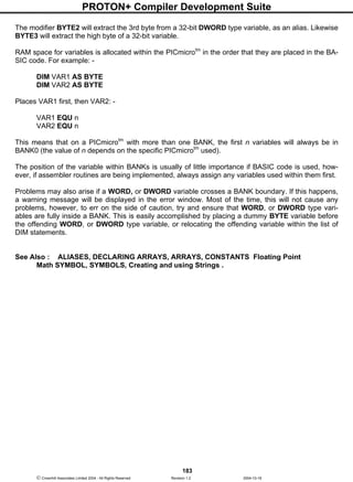
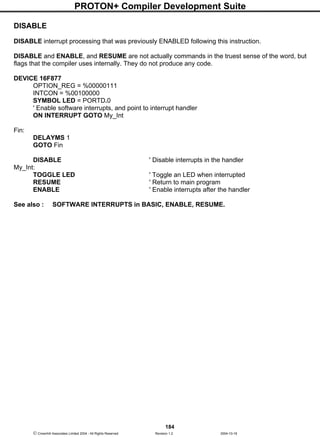
![PROTON+ Compiler Development Suite
185
Crownhill Associates Limited 2004 - All Rights Reserved Revision 1.2 2004-10-18
DTMFOUT
Syntax
DTMFOUT Pin , { OnTime } , { OffTime, } [ Tone {, Tone…} ]
Overview
Produce a DTMF Touch Tone sequence on Pin.
Operators
Pin is a PORT.BIT constant that specifies the I/O pin to use. This pin will be set to output during
generation of tones and set to input after the command is finished.
OnTime is an optional variable, constant, or expression (0 - 65535) specifying the duration, in ms, of
the tone. If the OnTime parameter is not used, then the default time is 200ms
OffTime is an optional variable, constant, or expression (0 - 65535) specifying the length of silent de-
lay, in ms, after a tone (or between tones, if multiple tones are specified). If the OffTime parameter is
not used, then the default time is 50ms
Tone may be a variable, constant, or expression (0 - 15) specifying the DTMF tone to generate. Tones
0 through 11 correspond to the standard layout of the telephone keypad, while 12 through 15 are the
fourth-column tones used by phone test equipment and in some radio applications.
Example
DTMFOUT PORTA.0 , [ 7 , 4 , 9 , 9 , 9 , 0 ] ' Call Crownhill.
If the PICmicrotm
was connected to the phone line correctly, the above command would dial 666-709.
If you wanted to slow down the dialling in order to break through a noisy phone line or radio link, you
could use the optional OnTime and OffTime values: -
‘Set the OnTime to 500ms and OffTime to 100ms
DTMFOUT PORTA.0 , 500 , 100 , [ 7 , 4 , 9 , 9 , 9 , 0 ] ' Call Crownhill Slowly.
Notes DTMF tones are used to dial a telephone, or re-
motely control pieces of radio equipment. The PICmicrotm
can
generate these tones digitally using the DTMFOUT
command. However, to achieve the best quality tones, a higher
crystal frequency is required. A 4MHz type will work but the
quality of the sound produced will suffer. The circuits
illustrate how to connect a speaker or audio amplifier to hear
the tones produced.
The PICmicrotm
is a digital device, however, DTMF tones are
analogue waveforms, consisting of a mixture of two sine waves
at different audio frequencies. So how can a digital device
generate an analogue output? The PICmicrotm
creates and
mixes two sine waves mathematically, then uses the resulting stream of numbers to control the duty
cycle of an extremely fast pulse-width modulation (PWM) routine. Therefore, what’s actually being
produced from the I/O pin is a rapid stream of pulses. The purpose of the filtering arrangements illus-
trated above is to smooth out the high-frequency PWM, leaving behind only the lower frequency audio.
You should keep this in mind if you wish to interface the PICmicro’s DTMF output to radios and other
equipment that could be adversely affected by the presence of high-frequency noise on the input.
Make sure to filter the DTMF output scrupulously. The circuits above are only a foundation; you may
want to use an active low-pass filter with a cut-off frequency of approximately 2KHz.
C2
0.1uF
R2
1k
To Audio
Amplifier
R1
1k
C1
0.1uF
From PIC
I/O pin
From PIC
I/O pin
Speaker
C1
10uF
C2
10uF](https://image.slidesharecdn.com/protondsuserguide-150604211022-lva1-app6891/85/Proton-ds-userguide-187-320.jpg)
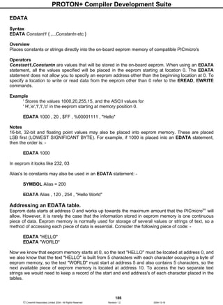
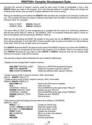
![PROTON+ Compiler Development Suite
189
Crownhill Associates Limited 2004 - All Rights Reserved Revision 1.2 2004-10-18
The example below illustrates the formatters in use.
' Convert a DWORD value into a string array
' Using only BASIC commands
' Similar principle to the STR$ command
INCLUDE "PROTON_4.INC"
DIM P10 AS DWORD ' Power of 10 variable
DIM CNT AS BYTE
DIM J AS BYTE
DIM VALUE AS DWORD ' Value to convert
DIM STRING1[11] AS BYTE ' Holds the converted value
DIM PTR AS BYTE ' Pointer within the Byte array
DELAYMS 500 ' Wait for PICmicro to stabilise
CLS ' Clear the LCD
CLEAR ' Clear all RAM before we start
VALUE = 1234576 ' Value to convert
GOSUB DWORD_TO_STR ' Convert VALUE to string
PRINT STR STRING1 ' Display the result
STOP
'-------------------------------------------------------------
' Convert a DWORD value into a string array
' Value to convert is placed in 'VALUE'
' Byte array 'STRING1' is built up with the ASCII equivalent
DWORD_TO_STR:
PTR = 0
J = 0
REPEAT
P10 = EREAD J * 4
CNT = 0
WHILE VALUE >= P10
VALUE = VALUE - P10
INC CNT
WEND
IF CNT <> 0 THEN
STRING1[PTR] = CNT + "0"
INC PTR
ENDIF
INC J
UNTIL J > 8
STRING1[PTR] = VALUE + "0"
INC PTR
STRING1[PTR] = 0 ' Add the NULL to terminate the string
RETURN
' EDATA table is formatted for all 32 bit values.
' Which means each value will require 4 bytes of eeprom space
EDATA AS DWORD 1000000000, 100000000, 10000000, 1000000,100000, 10000, 1000,_
100, 10](https://image.slidesharecdn.com/protondsuserguide-150604211022-lva1-app6891/85/Proton-ds-userguide-191-320.jpg)
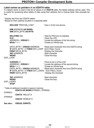
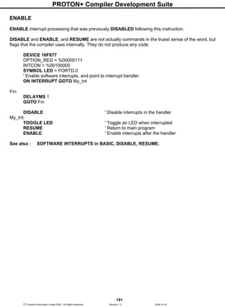
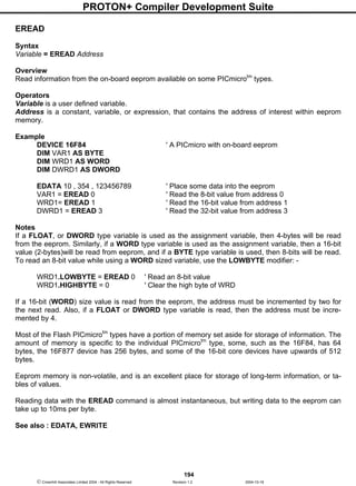
![PROTON+ Compiler Development Suite
195
Crownhill Associates Limited 2004 - All Rights Reserved Revision 1.2 2004-10-18
EWRITE
Syntax
EWRITE Address , [ Variable {, Variable…etc } ]
Overview
Write information to the on-board eeprom available on some PICmicrotm
types.
Operators
Address is a constant, variable, or expression, that contains the address of interest within eeprom
memory.
Variable is a user defined variable.
Example
DEVICE 16F628 ' A PICmicro with on-board eeprom
DIM VAR1 AS BYTE
DIM WRD1 AS WORD
DIM ADDRESS AS BYTE
VAR1 = 200
WRD1= 2456
ADDRESS = 0 ' Point to address 0 within the eeprom
EWRITE ADDRESS , [ WRD , VAR1 ] ' Write a 16-bit then an 8-bit value
Notes
If a DWORD type variable is used, then a 32-bit value (4-bytes) will be written to the eeprom. Similarly,
if a WORD type variable is used, then a 16-bit value (2-bytes) will be written to eeprom, and if a BYTE
type variable is used, then 8-bits will be written. To write an 8-bit value while using a WORD sized vari-
able, use the LOWBYTE modifier: -
EWRITE ADDRESS , [ WRD.LOWBYTE , VAR1 ]
If a 16-bit (WORD) size value is written to the eeprom, the address must be incremented by two before
the next write: -
FOR ADDRESS = 0 TO 64 STEP 2
EWRITE ADDRESS , [ WRD ]
NEXT
Most of the Flash PICmicrotm
types have a portion of memory set aside for storage of information. The
amount of memory is specific to the individual PICmicrotm
type, some, such as the 16F84, has 64
bytes, while the newer 16F877, and 18FXXX devices have 256 bytes.
Eeprom memory is non-volatile, and is an excellent place for storage of long-term information, or ta-
bles of values.
Writing data with the EWRITE command can take up to 10ms per byte, but reading data from the
eeprom is almost instantaneous,.
See also : EDATA, EREAD](https://image.slidesharecdn.com/protondsuserguide-150604211022-lva1-app6891/85/Proton-ds-userguide-197-320.jpg)
![PROTON+ Compiler Development Suite
196
Crownhill Associates Limited 2004 - All Rights Reserved Revision 1.2 2004-10-18
FOR...NEXT...STEP
Syntax
FOR Variable = Startcount TO Endcount [ STEP { Stepval } ]
{code body}
NEXT
Overview
The FOR…NEXT loop is used to execute a statement, or series of statements a predetermined
amount of times.
Operators
Variable refers to an index variable used for the sake of the loop. This index variable can itself be
used in the code body but beware of altering its value within the loop as this can cause many prob-
lems.
Startcount is the start number of the loop, which will initially be assigned to the variable. This does not
have to be an actual number - it could be the contents of another variable.
Endcount is the number on which the loop will finish. This does not have to be an actual number, it
could be the contents of another variable, or an expression.
Stepval is an optional constant or variable by which the variable increases or decreases with each trip
through the FOR-NEXT loop. If startcount is larger than endcount, then a minus sign must precede
stepval.
Example 1
' Display in decimal, all the values of WRD within an upward loop
DIM WRD AS WORD
FOR WRD = 0 TO 2000 STEP 2 ' Perform an upward loop
PRINT DEC WRD ," " ' Display the value of WRD
NEXT ' Close the loop
Example 2
' Display in decimal, all the values of WRD within a downward loop
DIM WRD AS WORD
FOR WRD = 2000 TO 0 STEP -2 ' Perform a downward loop
PRINT DEC WRD ," " ' Display the value of WRD
NEXT ' Close the loop
Example 3
' Display in decimal, all the values of DWRD within a downward loop
DIM DWRD AS DWORD
FOR DWRD = 200000 TO 0 STEP -200 ' Perform a downward loop
PRINT DEC DWRD ," " ' Display the value of DWRD
NEXT ' Close the loop](https://image.slidesharecdn.com/protondsuserguide-150604211022-lva1-app6891/85/Proton-ds-userguide-198-320.jpg)
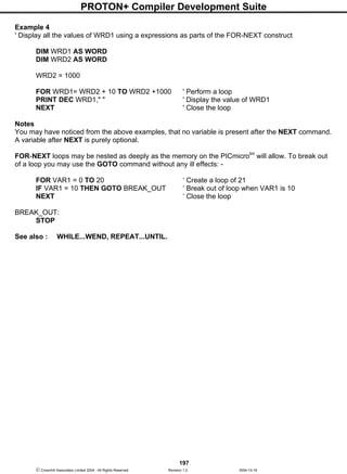
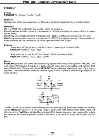
![PROTON+ Compiler Development Suite
199
Crownhill Associates Limited 2004 - All Rights Reserved Revision 1.2 2004-10-18
Example 2
‘ Play a tune using FREQOUT to generate the notes
DEVICE 16F877
DECLARE XTAL 20
DIM Loop AS BYTE ' Counter for notes.
DIM Freq1 AS WORD ' Frequency1.
DIM Freq2 AS WORD ' Frequency2
SYMBOL C = 2092 ' C note
SYMBOL D = 2348 ' D note
SYMBOL E = 2636 ' E note
SYMBOL G = 3136 ' G note
SYMBOL R = 0 ' Silent pause.
SYMBOL Pin = PORTA.0 ' Sound output pin
ADCON1 = 7 ' Set PORTA and PORTE to all digital
Loop = 0
REPEAT ' Create a loop for 29 notes within the LOOKUPL table.
Freq1 = LOOKUPL Loop , [E,D,C,D,E,E,E,R,D,D,D,R,E,G,G,R,E,D,C,D,E,E,E,E,D,D,E,D,C]
IF Freq1 = 0 THEN Freq2 = 0 : ELSE Freq2 = Freq1 - 8
FREQOUT Pin , 225 , Freq1 , Freq2
INC Loop
UNTIL Loop > 28
STOP
See also : DTMFOUT, SOUND, SOUND2.](https://image.slidesharecdn.com/protondsuserguide-150604211022-lva1-app6891/85/Proton-ds-userguide-201-320.jpg)
![PROTON+ Compiler Development Suite
201
Crownhill Associates Limited 2004 - All Rights Reserved Revision 1.2 2004-10-18
GOSUB
Syntax
GOSUB Label
or
GOSUB Label [Variable, {Variable, Variable... etc}] , Receipt Variable
Overview
GOSUB jumps the program to a defined label and continues execution from there. Once the program
hits a RETURN command the program returns to the instruction following the GOSUB that called it
and continues execution from that point.
If using a 16-bit core device, parameters can be pushed onto a software stack before the call is made,
and a variable can be popped from the stack before continuing execution of the next commands.
Operators
Label is a user-defined label placed at the beginning of a line which must have a colon ':' directly after
it.
Variable is a user defined variable of type BIT, BYTE, BYTE_ARRAY, WORD, WORD_ARRAY,
DWORD, FLOAT, or STRING, or constant value, that will be pushed onto the stack before the call to
a subroutine is performed.
Receipt Variable is a user defined variable of type BIT, BYTE, BYTE_ARRAY, WORD,
WORD_ARRAY, DWORD, FLOAT, or STRING, that will hold a value popped from the stack after the
subroutine has returned.
Example 1
' Implement a standard subroutine call
GOTO Start ' Jump over the subroutines
SubA: { subroutine A code
……
……
}
RETURN
SubB: { subroutine B code
……
……
}
RETURN
' Actual start of the main program
Start: GOSUB SubA
GOSUB SubB
STOP](https://image.slidesharecdn.com/protondsuserguide-150604211022-lva1-app6891/85/Proton-ds-userguide-203-320.jpg)
![PROTON+ Compiler Development Suite
202
Crownhill Associates Limited 2004 - All Rights Reserved Revision 1.2 2004-10-18
Example 2
' Call a subroutine with parameters
DEVICE = 18F452 ' Stack only suitable for 16-bit core devices
STACK_SIZE = 20 ' Create a small stack capable of holding 20 bytes
DIM WRD1 as WORD ' Create a WORD variable
DIM WRD2 as WORD ' Create another WORD variable
DIM RECEIPT as WORD ' Create a variable to hold result
WRD1 = 1234 ' Load the WORD variable with a value
WRD2 = 567 ' Load the other WORD variable with a value
' Call the subroutine and return a value
GOSUB ADD_THEM [WRD1 , WRD2] , RECEIPT
PRINT DEC RECEIPT ' Display the result as decimal
STOP
' Subroutine starts here. Add the two parameters passed and return the result
ADD_THEM:
DIM ADD_WRD1 as WORD ' Create two uniquely named variables
DIM ADD_WRD2 as WORD
POP ADD_WRD2 ' Pop the last variable pushed
POP ADD_WRD1 ' Pop the first variable pushed
ADD_WRD1 = ADD_WRD1 + ADD_WRD2 ' Add the values together
RETURN ADD_WRD1 ' Return the result of the addition
In reality, what's happening with the GOSUB in the above program is simple, if we break it into its con-
stituent events: -
PUSH WRD1
PUSH WRD2
GOSUB ADD_THEM
POP RECEIPT
Notes
Only one parameter can be returned from the subroutine, any others will be ignored.
If a parameter is to be returned from a subroutine but no parameters passed to the subroutine, simply
issue a pair of empty square braces: -
GOSUB LABEL [ ] , RECEIPT
The same rules apply for the parameters as they do for PUSH, which is after all, what is happening.
PROTON+ allows any amount of GOSUBs in a program, but the 14-bit PICmicrotm
architecture only
has an 8-level return address stack, which only allows 8 GOSUBs to be nested. The compiler only
ever uses a maximum of 4-levels for it's library subroutines, therefore do not use more than 4 GO-
SUBs within subroutines. The 16-bit core devices however, have a 28-level return address stack
which allows any combination of up to 28 GOSUBS to occur.
A subroutine must always end with a RETURN command.](https://image.slidesharecdn.com/protondsuserguide-150604211022-lva1-app6891/85/Proton-ds-userguide-204-320.jpg)
![PROTON+ Compiler Development Suite
206
Crownhill Associates Limited 2004 - All Rights Reserved Revision 1.2 2004-10-18
HBSTART
Syntax
HBSTART
Overview
Send a START condition to the I2
C bus using the PICmicro's MSSP module.
Notes
Because of the subtleties involved in interfacing to some I2
C devices, the compiler's standard
HBUSIN, and HBUSOUT commands were found lacking. Therefore, individual pieces of the I2
C proto-
col may be used in association with the new structure of HBUSIN, and HBUSOUT. See relevant sec-
tions for more information.
Example
' Interface to a 24LC32 serial eeprom
DEVICE = 16F877 ' Use a device with an MSSP module
DIM Loop AS BYTE
DIM Array[10] AS BYTE
' Transmit bytes to the I2C bus
HBSTART ' Send a START condition
HBUSOUT %10100000 ' Target an eeprom, and send a WRITE command
HBUSOUT 0 ' Send the HIGHBYTE of the address
HBUSOUT 0 ' Send the LOWBYTE of the address
FOR LOOP = 48 TO 57 ' Create a loop containing ASCII 0 to 9
HBUSOUT LOOP ' Send the value of LOOP to the eeprom
NEXT ' Close the loop
HBSTOP ' Send a STOP condition
DELAYMS 10 ' Wait for the data to be entered into eeprom matrix
' Receive bytes from the I2C bus
HBSTART ' Send a START condition
HBUSOUT %10100000 ' Target an eeprom, and send a WRITE command
HBUSOUT 0 ' Send the HIGHBYTE of the address
HBUSOUT 0 ' Send the LOWBYTE of the address
HBRESTART ' Send a RESTART condition
HBUSOUT %10100001 ' Target an eeprom, and send a READ command
FOR Loop = 0 TO 9 ' Create a loop
Array[Loop] = HBUSIN ' Load an array with bytes received
IF Loop = 9 THEN HBSTOP : ELSE HBUSACK ' ACK or STOP ?
NEXT ' Close the loop
PRINT AT 1,1, STR Array ' Display the Array as a STRING
See also : HBUSACK, HBRESTART, HBSTOP, HBUSIN, HBUSOUT.](https://image.slidesharecdn.com/protondsuserguide-150604211022-lva1-app6891/85/Proton-ds-userguide-208-320.jpg)
![PROTON+ Compiler Development Suite
208
Crownhill Associates Limited 2004 - All Rights Reserved Revision 1.2 2004-10-18
HBUSIN
Syntax
Variable = HBUSIN Control , { Address }
or
Variable = HBUSIN
or
HBUSIN Control , { Address }, [ Variable {, Variable…} ]
or
HBUSIN Variable
Overview
Receives a value from the I2
C bus using the MSSP module, and places it into variable/s. If structures
TWO or FOUR (see above) are used, then NO ACKNOWLEDGE, or STOP is sent after the data.
Structures ONE and THREE first send the control and optional address out of the clock pin (SCL), and
data pin (SDA).
Operators
Variable is a user defined variable or constant.
Control may be a constant value or a BYTE sized variable expression.
Address may be a constant value or a variable expression.
The four variations of the HBUSIN command may be used in the same BASIC program. The SEC-
OND and FOURTH types are useful for simply receiving a single byte from the bus, and must be used
in conjunction with one of the low level commands. i.e. HBSTART, HBRESTART, HBUSACK, or
HBSTOP. The FIRST, and THIRD types may be used to receive several values and designate each to
a separate variable, or variable type.
The HBUSIN command operates as an I2
C master, using the PICmicro's MSSP module, and may be
used to interface with any device that complies with the 2-wire I2
C protocol.
The most significant 7-bits of control byte contain the control code and the slave address of the device
being interfaced with. Bit-0 is the flag that indicates whether a read or write command is being imple-
mented.
For example, if we were interfacing to an external eeprom such as the 24C32, the control code would
be %10100001 or $A1. The most significant 4-bits (1010) are the eeprom's unique slave address. Bits
2 to 3 reflect the three address pins of the eeprom. And bit-0 is set to signify that we wish to read from
the eeprom. Note that this bit is automatically set by the HBUSIN command, regardless of its initial
setting.](https://image.slidesharecdn.com/protondsuserguide-150604211022-lva1-app6891/85/Proton-ds-userguide-210-320.jpg)
![PROTON+ Compiler Development Suite
209
Crownhill Associates Limited 2004 - All Rights Reserved Revision 1.2 2004-10-18
Example
' Receive a byte from the I2
C bus and place it into variable VAR1.
DIM VAR1 AS BYTE ' We'll only read 8-bits
DIM ADDRESS AS WORD ' 16-bit address required
SYMBOL Control %10100001 ' Target an eeprom
ADDRESS = 20 ' Read the value at address 20
VAR1 = HBUSIN Control , Address ' Read the byte from the eeprom
or
HBUSIN Control , ADDRESS, [ VAR1 ] ' Read the byte from the eeprom
Address, is an optional parameter that may be an 8-bit or 16-bit value. If a variable is used in this po-
sition, the size of address is dictated by the size of the variable used (BYTE or WORD). In the case of
the previous eeprom interfacing, the 24C32 eeprom requires a 16-bit address. While the smaller types
require an 8-bit address. Make sure you assign the right size address for the device interfaced with, or
you may not achieve the results you intended.
The value received from the bus depends on the size of the variables used, except for variation three,
which only receives a BYTE (8-bits). For example: -
DIM WRD AS WORD ' Declare a WORD size variable
WRD = HBUSIN Control , Address
Will receive a 16-bit value from the bus. While: -
DIM VAR1 AS BYTE ' Declare a BYTE size variable
VAR1 = HBUSIN Control , Address
Will receive an 8-bit value from the bus.
Using the THIRD variation of the HBUSIN command allows differing variable assignments. For exam-
ple: -
DIM VAR1 AS BYTE
DIM WRD AS WORD
HBUSIN Control , Address , [ VAR1 , WRD ]
Will receive two values from the bus, the first being an 8-bit value dictated by the size of variable
VAR1 which has been declared as a byte. And a 16-bit value, this time dictated by the size of the vari-
able WRD which has been declared as a word. Of course, BIT type variables may also be used, but in
most cases these are not of any practical use as they still take up a byte within the eeprom.
The SECOND and FOURTH variations allow all the subtleties of the I2
C protocol to be exploited, as
each operation may be broken down into its constituent parts. It is advisable to refer to the datasheet
of the device being interfaced to fully understand its requirements. See section on HBSTART,
HBRESTART, HBUSACK, or HBSTOP, for example code.
HBUSIN Declare
DECLARE HBUS_BITRATE Constant 100, 400, 1000](https://image.slidesharecdn.com/protondsuserguide-150604211022-lva1-app6891/85/Proton-ds-userguide-211-320.jpg)
![PROTON+ Compiler Development Suite
210
Crownhill Associates Limited 2004 - All Rights Reserved Revision 1.2 2004-10-18
The standard speed for the I2
C bus is 100KHz. Some devices use a higher bus speed of 400KHz. The
above DECLARE allows the I2
C bus speed to be increased or decreased. Use this DECLARE with
caution, as too high a bit rate may exceed the device's specs, which will result in intermittent transac-
tions, or in some cases, no transactions at all. The datasheet for the device used will inform you of its
bus speed. The default bit rate is the standard 100KHz.
Notes
Not all PICmicrotm
devices contain an MSSP module, some only contain an SSP type, which only al-
lows I2
C SLAVE operations. These types of devices may not be used with any of the HBUS com-
mands. Therefore, always read and understand the datasheet for the PICmicrotm
device used.
When the HBUSIN command is used, the appropriate SDA and SCL Port and Pin are automatically
setup as inputs. The SDA, and SCL lines are predetermined as hardware pins on the PICmicrotm
i.e.
For a 16F877 device, the SCL pin is PORTC.3, and SDA is PORTC.4. Therefore, there is no need to
pre-declare these.
Because the I2
C protocol calls for an open-collector interface, pull-up resistors are required on both
the SDA and SCL lines. Values of 4.7KΩ to 10KΩ will suffice.
STR modifier with HBUSIN
Using the STR modifier allows variations THREE and FOUR of the HBUSIN command to transfer the
bytes received from the I2
C bus directly into a byte array. If the amount of received characters is not
enough to fill the entire array, then a formatter may be placed after the array's name, which will only
receive characters until the specified length is reached. An example of each is shown below: -
DIM Array[10] AS BYTE ' Define an array of 10 bytes
DIM ADDRESS AS BYTE ' Create a word sized variable
HBUSIN %10100000 , ADDRESS, [ STR Array] ' Load data into all the array
' Load data into only the first 5 elements of the array
HBUSIN %10100000 , ADDRESS, [ STR Array5]
HBSTART ' Send a START condition
HBUSOUT %10100000 ' Target an eeprom, and send a WRITE command
HBUSOUT 0 ' Send the HIGHBYTE of the address
HBUSOUT 0 ' Send the LOWBYTE of the address
HBRESTART ' Send a RESTART condition
HBUSOUT %10100001 ' Target an eeprom, and send a READ command
HBUSIN STR Array ' Load all the array with bytes received
HBSTOP ' Send a STOP condition
An alternative ending to the above example is: -
HBUSIN STR Array5 ' Load data into only the first 5 elements of the array
HBSTOP ' Send a STOP condition
See also : HBUSACK, HBRESTART, HBSTOP, HBSTART, HBUSOUT.](https://image.slidesharecdn.com/protondsuserguide-150604211022-lva1-app6891/85/Proton-ds-userguide-212-320.jpg)
![PROTON+ Compiler Development Suite
211
Crownhill Associates Limited 2004 - All Rights Reserved Revision 1.2 2004-10-18
HBUSOUT
Syntax
HBUSOUT Control , { Address } , [ Variable {, Variable…} ]
or
HBUSOUT Variable
Overview
Transmit a value to the I2
C bus using the PICmicro's on-board MSSP module, by first sending the con-
trol and optional address out of the clock pin (SCL), and data pin (SDA). Or alternatively, if only one
operator is included after the HBUSOUT command, a single value will be transmitted, along with an
ACK reception.
Operators
Variable is a user defined variable or constant.
Control may be a constant value or a BYTE sized variable expression.
Address may be a constant, variable, or expression.
The HBUSOUT command operates as an I2
C master and may be used to interface with any device
that complies with the 2-wire I2
C protocol.
The most significant 7-bits of control byte contain the control code and the slave address of the device
being interfaced with. Bit-0 is the flag that indicates whether a read or write command is being imple-
mented.
For example, if we were interfacing to an external eeprom such as the 24C32, the control code would
be %10100000 or $A0. The most significant 4-bits (1010) are the eeprom's unique slave address. Bits
2 to 3 reflect the three address pins of the eeprom. And Bit-0 is clear to signify that we wish to write to
the eeprom. Note that this bit is automatically cleared by the HBUSOUT command, regardless of its
initial value.
Example
' Send a byte to the I2
C bus.
DIM VAR1 AS BYTE ' We'll only read 8-bits
DIM ADDRESS AS WORD ' 16-bit address required
SYMBOL Control = %10100000 ' Target an eeprom
ADDRESS = 20 ' Write to address 20
VAR1 = 200 ' The value place into address 20
HBUSOUT Control , ADDRESS, [ VAR1 ] ' Send the byte to the eeprom
DELAYMS 10 ' Allow time for allocation of byte
Address, is an optional parameter that may be an 8-bit or 16-bit value. If a variable is used in this po-
sition, the size of address is dictated by the size of the variable used (BYTE or WORD). In the case of
the above eeprom interfacing, the 24C32 eeprom requires a 16-bit address. While the smaller types
require an 8-bit address. Make sure you assign the right size address for the device interfaced with, or
you may not achieve the results you intended.](https://image.slidesharecdn.com/protondsuserguide-150604211022-lva1-app6891/85/Proton-ds-userguide-213-320.jpg)
![PROTON+ Compiler Development Suite
212
Crownhill Associates Limited 2004 - All Rights Reserved Revision 1.2 2004-10-18
The value sent to the bus depends on the size of the variables used. For example: -
DIM WRD AS WORD ' Declare a WORD size variable
HBUSOUT Control , Address , [ WRD ]
Will send a 16-bit value to the bus. While: -
DIM VAR1 AS BYTE ' Declare a BYTE size variable
HBUSOUT Control , Address , [ VAR1 ]
Will send an 8-bit value to the bus.
Using more than one variable within the brackets allows differing variable sizes to be sent. For exam-
ple: -
DIM VAR1 AS BYTE
DIM WRD AS WORD
HBUSOUT Control , Address , [ VAR1 , WRD ]
Will send two values to the bus, the first being an 8-bit value dictated by the size of variable VAR1
which has been declared as a byte. And a 16-bit value, this time dictated by the size of the variable
WRD which has been declared as a word. Of course, BIT type variables may also be used, but in
most cases these are not of any practical use as they still take up a byte within the eeprom.
A string of characters can also be transmitted, by enclosing them in quotes: -
HBUSOUT Control , Address , [ "Hello World" , VAR1 , WRD ]
Using the second variation of the HBUSOUT command, necessitates using the low level commands
i.e. HBSTART, HBRESTART, HBUSACK, or HBSTOP.
Using the HBUSOUT command with only one value after it, sends a byte of data to the I2
C bus, and
returns holding the ACKNOWLEDGE reception. This acknowledge indicates whether the data has
been received by the slave device.
The ACK reception is returned in the PICmicro's CARRY flag, which is STATUS.0, and also SYSTEM
variable PP4.0. A value of zero indicates that the data was received correctly, while a one indicates
that the data was not received, or that the slave device has sent a NACK return. You must read and
understand the datasheet for the device being interfacing to, before the ACK return can be used suc-
cessfully. An code snippet is shown below: -
' Transmit a byte to a 24LC32 serial eeprom
DIM PP4 AS BYTE SYSTEM
HBSTART ' Send a START condition
HBUSOUT %10100000 ' Target an eeprom, and send a WRITE command
HBUSOUT 0 ' Send the HIGHBYTE of the address
HBUSOUT 0 ' Send the LOWBYTE of the address
HBUSOUT "A" ' Send the value 65 to the bus
IF PP4.0 = 1 THEN GOTO Not_Received ' Has ACK been received OK ?
HBSTOP ' Send a STOP condition
DELAYMS 10 ' Wait for the data to be entered into eeprom matrix](https://image.slidesharecdn.com/protondsuserguide-150604211022-lva1-app6891/85/Proton-ds-userguide-214-320.jpg)
![PROTON+ Compiler Development Suite
213
Crownhill Associates Limited 2004 - All Rights Reserved Revision 1.2 2004-10-18
STR modifier with HBUSOUT.
The STR modifier is used for transmitting a string of bytes from a byte array variable. A string is a set
of bytes sized values that are arranged or accessed in a certain order. The values 1, 2, 3 would be
stored in a string with the value 1 first, followed by 2 then followed by the value 3. A byte array is a
similar concept to a string; it contains data that is arranged in a certain order. Each of the elements in
an array is the same size. The string 1,2,3 would be stored in a byte array containing three bytes
(elements).
Below is an example that sends four bytes from an array: -
DIM MYARRAY[10] AS BYTE ' Create a 10-byte array.
MYARRAY [0] = "A" ' Load the first 4 bytes of the array
MYARRAY [1] = "B" ' With the data to send
MYARRAY [2] = "C"
MYARRAY [3] = "D"
HBUSOUT %10100000 , Address , [ STR MYARRAY 4 ] ' Send 4-byte string.
Note that we use the optional n argument of STR. If we didn't specify this, the program would try to
keep sending characters until all 10 bytes of the array were transmitted. Since we do not wish all 10
bytes to be transmitted, we chose to tell it explicitly to only send the first 4 bytes.
The above example may also be written as: -
DIM MYARRAY [10] AS BYTE ' Create a 10-byte array.
STR MYARRAY = "ABCD" ' Load the first 4 bytes of the array
HBSTART ' Send a START condition
HBUSOUT %10100000 ' Target an eeprom, and send a WRITE command
HBUSOUT 0 ' Send the HIGHBYTE of the address
HBUSOUT 0 ' Send the LOWBYTE of the address
HBUSOUT STR MYARRAY 4 ' Send 4-byte string.
HBSTOP ' Send a STOP condition
The above example, has exactly the same function as the previous one. The only differences are that
the string is now constructed using the STR as a command instead of a modifier, and the low-level
HBUS commands have been used.
Notes
Not all PICmicrotm
devices contain an MSSP module, some only contain an SSP type, which only al-
lows I2
C SLAVE operations. These types of devices may not be used with any of the HBUS com-
mands. Therefore, always read and understand the datasheet for the PICmicrotm
device used.
When the HBUSOUT command is used, the appropriate SDA and SCL Port and Pin are automatically
setup as inputs. The SDA, and SCL lines are predetermined as hardware pins on the PICmicrotm
i.e.
For a 16F877 device, the SCL pin is PORTC.3, and SDA is PORTC.4. Therefore, there is no need to
pre-declare these. Because the I2
C protocol calls for an open-collector interface, pull-up resistors are
required on both the SDA and SCL lines. Values of 4.7K to 10K will suffice.
See also : HBUSACK, HBRESTART, HBSTOP, HBUSIN, HBSTART.](https://image.slidesharecdn.com/protondsuserguide-150604211022-lva1-app6891/85/Proton-ds-userguide-215-320.jpg)
![PROTON+ Compiler Development Suite
219
Crownhill Associates Limited 2004 - All Rights Reserved Revision 1.2 2004-10-18
The above code waits for the characters "X", "Y" and "Z" to be received, in that order, then it receives
the next data byte and places it into variable SERDATA.
STR modifier.
The HRSIN command also has a modifier for handling a string of characters, named STR.
The STR modifier is used for receiving a string of characters into a byte array variable.
A string is a set of characters that are arranged or accessed in a certain order. The characters "ABC"
would be stored in a string with the "A" first, followed by the "B" then followed by the "C". A byte array
is a similar concept to a string; it contains data that is arranged in a certain order. Each of the ele-
ments in an array is the same size. The string "ABC" would be stored in a byte array containing three
bytes (elements).
Below is an example that receives ten bytes and stores them in the 10-byte array, SERSTRING: -
DIM SerString[10] AS BYTE ' Create a 10-byte array.
HRSIN STR SerString ' Fill the array with received data.
PRINT STR SerString ' Display the string.
If the amount of received characters is not enough to fill the entire array, then a formatter may be
placed after the array's name, which will only receive characters until the specified length is reached.
For example: -
DIM SerString[10] AS BYTE ' Create a 10-byte array.
HRSIN STR SerString5 ' Fill the first 5-bytes of the array
PRINT STR SerString5 ' Display the 5-character string.
The example above illustrates how to fill only the first n bytes of an array, and then how to display only
the first n bytes of the array. n refers to the value placed after the backslash.
Because of its complexity, serial communication can be rather difficult to work with at times. Using the
guidelines below when developing a project using the HRSIN and HRSOUT commands may help to
eliminate some obvious errors: -
Always build your project in steps.
Start with small, manageable pieces of code, (that deal with serial communication) and test them, one
individually.
Add more and more small pieces, testing them each time, as you go.
Never write a large portion of code that works with serial communication without testing its smallest
workable pieces first.
Pay attention to timing.
Be careful to calculate and overestimate the amount of time, operations should take within the
PICmicrotm
for a given oscillator frequency. Misunderstanding the timing constraints is the source of
most problems with code that communicate serially. If the serial communication in your project is bi-
directional, the above statement is even more critical.
Pay attention to wiring.
Take extra time to study and verify serial communication wiring diagrams. A mistake in wiring can
cause strange problems in communication, or no communication at all. Make sure to connect the
ground pins (Vss) between the devices that are communicating serially.](https://image.slidesharecdn.com/protondsuserguide-150604211022-lva1-app6891/85/Proton-ds-userguide-221-320.jpg)

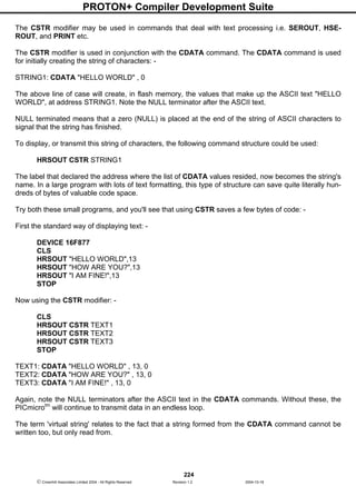
![PROTON+ Compiler Development Suite
225
Crownhill Associates Limited 2004 - All Rights Reserved Revision 1.2 2004-10-18
The STR modifier is used for sending a string of bytes from a byte array variable. A string is a set of
bytes sized values that are arranged or accessed in a certain order. The values 1, 2, 3 would be
stored in a string with the value 1 first, followed by 2 then followed by the value 3. A byte array is a
similar concept to a string; it contains data that is arranged in a certain order. Each of the elements in
an array is the same size. The string 1,2,3 would be stored in a byte array containing three bytes
(elements).
Below is an example that displays four bytes (from a byte array): -
DIM MYARRAY[10] AS BYTE ' Create a 10-byte array.
MYARRAY [0] = "H" ' Load the first 5 bytes of the array
MYARRAY [1] = "E" ' With the data to send
MYARRAY [2] = "L"
MYARRAY [3] = "L"
MYARRAY [4] = "O"
HRSOUT STR MYARRAY 5 ' Display a 5-byte string.
Note that we use the optional n argument of STR. If we didn't specify this, the PICmicrotm
would try to
keep sending characters until all 10 bytes of the array were transmitted. Since we do not wish all 10
bytes to be transmitted, we chose to tell it explicitly to only send the first 5 bytes.
The above example may also be written as: -
DIM MYARRAY [10] AS BYTE ' Create a 10-byte array.
STR MYARRAY = "HELLO" ' Load the first 5 bytes of the array
HRSOUT STR MYARRAY 5 ' Send 5-byte string.
The above example, has exactly the same function as the previous one. The only difference is that the
string is now constructed using STR as a command instead of a modifier.
Declares
There are four DECLARE directives for use with HRSOUT. These are: -
DECLARE HSERIAL_BAUD Constant value
Sets the BAUD rate that will be used to transmit a value serially. The baud rate is calculated using the
XTAL frequency declared in the program. The default baud rate if the DECLARE is not included in the
program listing is 2400 baud.
DECLARE HSERIAL_RCSTA Constant value (0 to 255)
HSERIAL_RCSTA, sets the respective PICmicrotm
hardware register RCSTA, to the value in the DE-
CLARE. See the Microchip data sheet for the device used for more information regarding this register.
Refer to the upgrade manual pages for a description of the RCSTA register.
DECLARE HSERIAL_TXSTA Constant value (0 to 255)
HSERIAL_TXSTA, sets the respective PICmicrotm
hardware register, TXSTA, to the value in the DE-
CLARE. See the Microchip data sheet for the device used for more information regarding this register.
The TXSTA register BRGH bit (bit 2) controls the high speed mode for the baud rate generator. Cer-
tain baud rates at certain oscillator speeds require this bit to be set to operate properly. To do this, set
HSERIAL_TXSTA to a value of 24h instead of the normal 20h. Refer to the Microchip data sheet for
the hardware serial port baud rate tables and additional information. Refer to the upgrade manual
pages for a description of the TXSTA register.](https://image.slidesharecdn.com/protondsuserguide-150604211022-lva1-app6891/85/Proton-ds-userguide-227-320.jpg)
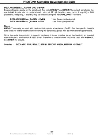
![PROTON+ Compiler Development Suite
227
Crownhill Associates Limited 2004 - All Rights Reserved Revision 1.2 2004-10-18
HSERIN
Syntax
HSERIN Timeout , Timeout Label , Parity Error Label , [Modifiers , Variable {, Variable... }]
Overview
Receive one or more values from the serial port on devices that contain a hardware USART. (Com-
patible with the melabs compiler)
Operators
Timeout is an OPTIONAL value for the length of time the HRSIN command will wait before jumping to
label TIMEOUT LABEL. Timeout is specified in 1 millisecond units.
Timeout Label is an OPTIONAL valid BASIC label where HRSIN will jump to in the event that a char-
acter has not been received within the time specified by TIMEOUT.
Parity Error Label is an OPTIONAL valid BASIC label where HRSIN will jump to in the event that a
PARITY error is received. Parity is set using DECLARES. Parity Error detecting is not supported in the
inline version of HRSIN (first syntax example above).
Modifier is one of the many formatting modifiers, explained below.
Variable is a BIT, BYTE, WORD, or DWORD variable, that will be loaded by HSERIN.
Example
' Receive values serially and timeout if no reception after 1 second (1000ms).
DEVICE 16F877
XTAL = 4
HSERIAL_BAUD = 9600 ' Set baud rate to 9600
HSERIAL_RCSTA = %10010000 ' Enable serial port and continuous receive
HSERIAL_TXSTA = %00100000 ' Enable transmit and asynchronous mode
HSERIAL_CLEAR = ON ' Optionally clear the buffer before receiving
DIM VAR1 AS BYTE
Loop: HSERIN 1000 , Timeout , [VAR1] ' Receive a byte serially into VAR1
PRINT DEC VAR1 , " " ' Display the byte received
GOTO Loop ' Loop forever
Timeout:
CLS
PRINT "TIMED OUT" ' Display an error if HSERIN timed out
STOP
HSERIN MODIFIERS.
As we already know, HSERIN will wait for and receive a single byte of data, and store it in a variable .
If the PICmicrotm
were connected to a PC running a terminal program and the user pressed the "A"
key on the keyboard, after the HSERIN command executed, the variable would contain 65, which is
the ASCII code for the letter "A"
What would happen if the user pressed the "1" key? The result would be that the variable would con-
tain the value 49 (the ASCII code for the character "1"). This is an important point to remember: every
time you press a character on the keyboard, the computer receives the ASCII value of that character.
It is up to the receiving side to interpret the values as necessary. In this case, perhaps we actually
wanted the variable to end up with the value 1, rather than the ASCII code 49.](https://image.slidesharecdn.com/protondsuserguide-150604211022-lva1-app6891/85/Proton-ds-userguide-229-320.jpg)
![PROTON+ Compiler Development Suite
228
Crownhill Associates Limited 2004 - All Rights Reserved Revision 1.2 2004-10-18
The HSERIN command provides a modifier, called the decimal modifier, which will interpret this for us.
Look at the following code: -
DIM SERDATA AS BYTE
HSERIN [DEC SERDATA]
Notice the decimal modifier in the HSERIN command that appears just to the left of the SERDATA
variable. This tells HSERIN to convert incoming text representing decimal numbers into true decimal
form and store the result in SERDATA. If the user running the terminal software pressed the "1", "2"
and then "3" keys followed by a space or other non-numeric text, the value 123 will be stored in the
variable SERDATA, allowing the rest of the program to perform any numeric operation on the variable.
Without the decimal modifier, however, you would have been forced to receive each character ("1", "2"
and "3") separately, and then would still have to do some manual conversion to arrive at the number
123 (one hundred twenty three) before you can do the desired calculations on it.
The decimal modifier is designed to seek out text that represents decimal numbers. The characters
that represent decimal numbers are the characters "0" through "9". Once the HSERIN command is
asked to use the decimal modifier for a particular variable, it monitors the incoming serial data, looking
for the first decimal character. Once it finds the first decimal character, it will continue looking for more
(accumulating the entire multi-digit number) until is finds a non-decimal numeric character. Remember
that it will not finish until it finds at least one decimal character followed by at least one non-decimal
character.
To illustrate this further, examine the following examples (assuming we're using the same code exam-
ple as above): -
Serial input: "ABC"
Result: The program halts at the HSERIN command, continuously waiting for decimal text.
Serial input: "123" (with no characters following it)
Result: The program halts at the HSERIN command. It recognises the characters "1", "2" and "3" as
the number one hundred twenty three, but since no characters follow the "3", it waits continuously,
since there's no way to tell whether 123 is the entire number or not.
Serial input: "123" (followed by a space character)
Result: Similar to the above example, except once the space character is received, the program
knows the entire number is 123, and stores this value in SERDATA. The HSERIN command then
ends, allowing the next line of code to run.
Serial input: "123A"
Result: Same as the example above. The "A" character, just like the space character, is the first non-
decimal text after the number 123, indicating to the program that it has received the entire number.
Serial input: "ABCD123EFGH"
Result: Similar to examples 3 and 4 above. The characters "ABCD" are ignored (since they're not
decimal text), the characters "123" are evaluated to be the number 123 and the following character,
"E", indicates to the program that it has received the entire number.
The final result of the DEC modifier is limited to 16 bits (up to the value 65535). If a value larger than
this is received by the decimal modifier, the end result will be incorrect because the](https://image.slidesharecdn.com/protondsuserguide-150604211022-lva1-app6891/85/Proton-ds-userguide-230-320.jpg)
![PROTON+ Compiler Development Suite
229
Crownhill Associates Limited 2004 - All Rights Reserved Revision 1.2 2004-10-18
result rolled-over the maximum 16-bit value. Therefore, HSERIN modifiers may not (at this time) be
used to load DWORD (32-bit) variables.
The decimal modifier is only one of a family of conversion modifiers available with HSERIN See below
for a list of available conversion modifiers. All of the conversion modifiers work similar to the decimal
modifier (as described above). The modifiers receive bytes of data, waiting for the first byte that falls
within the range of characters they accept (e.g., "0" or "1" for binary, "0" to "9" for decimal, "0" to "9"
and "A" to "F" for hex. Once they receive a numeric character, they keep accepting input until a non-
numeric character arrives, or in the case of the fixed length modifiers, the maximum specified number
of digits arrives.
While very effective at filtering and converting input text, the modifiers aren't completely foolproof. As
mentioned before, many conversion modifiers will keep accepting text until the first non-numeric text
arrives, even if the resulting value exceeds the size of the variable. After HSERIN, a BYTE variable
will contain the lowest 8 bits of the value entered and a WORD (16-bits) would contain the lowest 16
bits. You can control this to some degree by using a modifier that specifies the number of digits, such
as DEC2, which would accept values only in the range of 0 to 99.
Conversion Modifier Type of Number Numeric Characters Accepted
DEC{1..10} Decimal, optionally limited 0 through 9
to 1 - 10 digits
HEX{1..8} Hexadecimal, optionally limited 0 through 9,
to 1 - 8 digits A through F
BIN{1..32} Binary, optionally limited 0, 1
to 1 - 32 digits
A variable preceded by BIN will receive the ASCII representation of its binary value.
For example, if BIN VAR1 is specified and "1000" is received, VAR1 will be set to 8.
A variable preceded by DEC will receive the ASCII representation of its decimal value.
For example, if DEC VAR1 is specified and "123" is received, VAR1 will be set to 123.
A variable preceded by HEX will receive the ASCII representation of its hexadecimal value.
For example, if HEX VAR1 is specified and "FE" is received, VAR1 will be set to 254.
SKIP followed by a count will skip that many characters in the input stream.
For example, SKIP 4 will skip 4 characters.
The HSERIN command can be configured to wait for a specified sequence of characters before it re-
trieves any additional input. For example, suppose a device attached to the PICmicrotm
is known to
send many different sequences of data, but the only data you wish to observe happens to appear right
after the unique characters, "XYZ". A modifier named WAIT can be used for this purpose: -
HSERIN [WAIT( "XYZ" ) , SERDATA]
The above code waits for the characters "X", "Y" and "Z" to be received, in that order, then it receives
the next data byte and places it into variable SERDATA.](https://image.slidesharecdn.com/protondsuserguide-150604211022-lva1-app6891/85/Proton-ds-userguide-231-320.jpg)
![PROTON+ Compiler Development Suite
230
Crownhill Associates Limited 2004 - All Rights Reserved Revision 1.2 2004-10-18
STR modifier.
The HSERIN command also has a modifier for handling a string of characters, named STR.
The STR modifier is used for receiving a string of characters into a byte array variable.
A string is a set of characters that are arranged or accessed in a certain order. The characters "ABC"
would be stored in a string with the "A" first, followed by the "B" then followed by the "C". A byte array
is a similar concept to a string; it contains data that is arranged in a certain order. Each of the ele-
ments in an array is the same size. The string "ABC" would be stored in a byte array containing three
bytes (elements).
Below is an example that receives ten bytes and stores them in the 10-byte array, SERSTRING: -
DIM SerString[10] AS BYTE ' Create a 10-byte array.
HSERIN [STR SerString] ' Fill the array with received data.
PRINT STR SerString ' Display the string.
If the amount of received characters is not enough to fill the entire array, then a formatter may be
placed after the array's name, which will only receive characters until the specified length is reached.
For example: -
DIM SerString[10] AS BYTE ' Create a 10-byte array.
HSERIN [STR SerString5] ' Fill the first 5-bytes of the array
PRINT STR SerString5 ' Display the 5-character string.
The example above illustrates how to fill only the first n bytes of an array, and then how to display only
the first n bytes of the array. n refers to the value placed after the backslash.
Because of its complexity, serial communication can be rather difficult to work with at times. Using the
guidelines below when developing a project using the HSERIN and HSEROUT commands may help
to eliminate some obvious errors: -
Always build your project in steps.
Start with small, manageable pieces of code, (that deal with serial communication) and test them, one
individually.
Add more and more small pieces, testing them each time, as you go.
Never write a large portion of code that works with serial communication without testing its smallest
workable pieces first.
Pay attention to timing.
Be careful to calculate and overestimate the amount of time, operations should take within the
PICmicrotm
for a given oscillator frequency. Misunderstanding the timing constraints is the source of
most problems with code that communicate serially. If the serial communication in your project is bi-
directional, the above statement is even more critical.
Pay attention to wiring.
Take extra time to study and verify serial communication wiring diagrams. A mistake in wiring can
cause strange problems in communication, or no communication at all. Make sure to connect the
ground pins (Vss) between the devices that are communicating serially.](https://image.slidesharecdn.com/protondsuserguide-150604211022-lva1-app6891/85/Proton-ds-userguide-232-320.jpg)

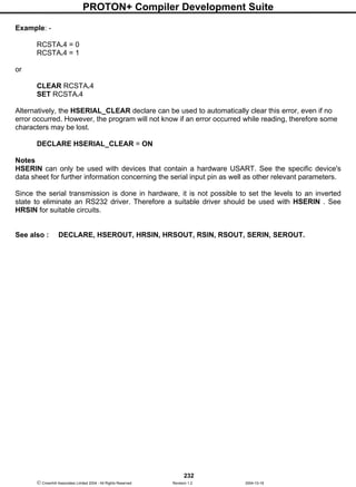
![PROTON+ Compiler Development Suite
233
Crownhill Associates Limited 2004 - All Rights Reserved Revision 1.2 2004-10-18
HSEROUT
Syntax
HSEROUT [Item { , Item... }]
Overview
Transmit one or more Items from the hardware serial port on devices that support asynchronous serial
communications in hardware.
Operators
Item may be a constant, variable, expression, string list, or inline command.
There are no operators as such, instead there are modifiers. For example, if an at sign'@' precedes an
Item, the ASCII representation for each digit is transmitted.
The modifiers are listed below: -
Modifier Operation
AT ypos,xpos Position the cursor on a serial LCD
CLS Clear a serial LCD (also creates a 30ms delay)
BIN{1..32} Send binary digits
DEC{1..10} Send decimal digits
HEX{1..8} Send hexadecimal digits
SBIN{1..32} Send signed binary digits
SDEC{1..10} Send signed decimal digits
SHEX{1..8} Send signed hexadecimal digits
IBIN{1..32} Send binary digits with a preceding '%' identifier
IDEC{1..10} Send decimal digits with a preceding '#' identifier
IHEX{1..8} Send hexadecimal digits with a preceding '$' identifier
ISBIN{1..32} Send signed binary digits with a preceding '%' identifier
ISDEC{1..10} Send signed decimal digits with a preceding '#' identifier
ISHEX{1..8} Send signed hexadecimal digits with a preceding '$' identifier
REP cn Send character c repeated n times
STR arrayn Send all or part of an array
CSTR cdata Send string data defined in a CDATA statement.
The numbers after the BIN, DEC, and HEX modifiers are optional. If they are omitted, then the default
is all the digits that make up the value will be displayed.
If a floating point variable is to be displayed, then the digits after the DEC modifier determine how
many remainder digits are send. i.e. numbers after the decimal point.
DIM FLT AS FLOAT
FLT = 3.145
HSEROUT [DEC2 FLT] ' Send 2 values after the decimal point
The above program will send 3.14](https://image.slidesharecdn.com/protondsuserguide-150604211022-lva1-app6891/85/Proton-ds-userguide-235-320.jpg)
![PROTON+ Compiler Development Suite
234
Crownhill Associates Limited 2004 - All Rights Reserved Revision 1.2 2004-10-18
If the digit after the DEC modifier is omitted, then 3 values will be displayed after the decimal point.
DIM FLT AS FLOAT
FLT = 3.1456
HSEROUT [DEC FLT] ' Send 3 values after the decimal point
The above program will send 3.145
There is no need to use the SDEC modifier for signed floating point values, as the compiler's DEC
modifier will automatically display a minus result: -
DIM FLT AS FLOAT
FLT = -3.1456
HSEROUT [DEC FLT] ' Send 3 values after the decimal point
The above program will send -3.145
HEX or BIN modifiers cannot be used with floating point values or variables.
The Xpos and Ypos values in the AT modifier both start at 1. For example, to place the text "HELLO
WORLD" on line 1, position 1, the code would be: -
HSEROUT [AT 1 , 1 , "HELLO WORLD"]
Example 1
DIM VAR1 AS BYTE
DIM WRD AS WORD
DIM DWD AS DWORD
HSEROUT ["Hello World" ' Display the text "Hello World"
HSEROUT ["VAR1= " , DEC VAR1] ' Display the decimal value of VAR1
HSEROUT ["VAR1= " , HEX VAR1] ' Display the hexadecimal value of VAR1
HSEROUT ["VAR1= " , BIN VAR1] ' Display the binary value of VAR1
HSEROUT ["VAR1= " , @VAR1] ' Display the decimal value of VAR1
' Display 6 hex characters of a DWORD type variable
HSEROUT ["DWD= " , HEX6 DWD]
Example 2
' Display a negative value on a serial LCD.
SYMBOL NEGATIVE = -200
HSEROUT [AT 1 , 1 , SDEC NEGATIVE]
Example 3
' Display a negative value on a serial LCD with a preceding identifier.
HSEROUT [AT 1 , 1 , ISHEX -$1234]
Example 3 will produce the text "$-1234" on the LCD.
Some PICmicros such as the 16F87x, and 18FXXX range have the ability to read and write to their
own flash memory. And although writing to this memory too many times is unhealthy for the
PICmicrotm
, reading this memory is both fast, and harmless.](https://image.slidesharecdn.com/protondsuserguide-150604211022-lva1-app6891/85/Proton-ds-userguide-236-320.jpg)
![PROTON+ Compiler Development Suite
235
Crownhill Associates Limited 2004 - All Rights Reserved Revision 1.2 2004-10-18
Which offers a unique form of data storage and retrieval, the CDATA command proves this, as it uses
the mechanism of reading and storing in the PICmicro's flash memory.
Combining the unique features of the ‘self modifying PICmicro's' with a string format, the compiler is
capable of reducing the overhead of printing, or transmitting large amounts of text data. The CSTR
modifier may be used in commands that deal with text processing i.e. SEROUT, HRSOUT, and PRINT
etc.
The CSTR modifier is used in conjunction with the CDATA command. The CDATA command is used
for initially creating the string of characters: -
STRING1: CDATA "HELLO WORLD" , 0
The above line of case will create, in flash memory, the values that make up the ASCII text "HELLO
WORLD", at address STRING1. Note the NULL terminator after the ASCII text.
NULL terminated means that a zero (NULL) is placed at the end of the string of ASCII characters to
signal that the string has finished.
To display, or transmit this string of characters, the following command structure could be used:
HSEROUT [CSTR STRING1]
The label that declared the address where the list of CDATA values resided, now becomes the string's
name. In a large program with lots of text formatting, this type of structure can save quite literally hun-
dreds of bytes of valuable code space.
Try both these small programs, and you'll see that using CSTR saves a few bytes of code: -
First the standard way of displaying text: -
DEVICE 16F877
CLS
HSEROUT ["HELLO WORLD",13]
HSEROUT ["HOW ARE YOU?",13]
HSEROUT ["I AM FINE!",13]
STOP
Now using the CSTR modifier: -
CLS
HSEROUT [CSTR TEXT1]
HSEROUT [CSTR TEXT2]
HSEROUT [CSTR TEXT3]
STOP
TEXT1: CDATA "HELLO WORLD" , 13, 0
TEXT2: CDATA "HOW ARE YOU?" , 13, 0
TEXT3: CDATA "I AM FINE!" , 13, 0
Again, note the NULL terminators after the ASCII text in the CDATA commands. Without these, the
PICmicrotm
will continue to transmit data in an endless loop.](https://image.slidesharecdn.com/protondsuserguide-150604211022-lva1-app6891/85/Proton-ds-userguide-237-320.jpg)
![PROTON+ Compiler Development Suite
236
Crownhill Associates Limited 2004 - All Rights Reserved Revision 1.2 2004-10-18
The term 'virtual string' relates to the fact that a string formed from the CDATA command cannot be
written too, but only read from.
The STR modifier is used for sending a string of bytes from a byte array variable. A string is a set of
bytes sized values that are arranged or accessed in a certain order. The values 1, 2, 3 would be
stored in a string with the value 1 first, followed by 2 then followed by the value 3. A byte array is a
similar concept to a string; it contains data that is arranged in a certain order. Each of the elements in
an array is the same size. The string 1,2,3 would be stored in a byte array containing three bytes
(elements).
Below is an example that displays four bytes (from a byte array): -
DIM MYARRAY[10] AS BYTE ' Create a 10-byte array.
MYARRAY [0] = "H" ' Load the first 5 bytes of the array
MYARRAY [1] = "E" ' With the data to send
MYARRAY [2] = "L"
MYARRAY [3] = "L"
MYARRAY [4] = "O"
HRSOUT STR MYARRAY 5 ' Display a 5-byte string.
Note that we use the optional n argument of STR. If we didn't specify this, the PICmicrotm
would try to
keep sending characters until all 10 bytes of the array were transmitted. Since we do not wish all 10
bytes to be transmitted, we chose to tell it explicitly to only send the first 5 bytes.
The above example may also be written as: -
DIM MYARRAY [10] AS BYTE ' Create a 10-byte array.
STR MYARRAY = "HELLO" ' Load the first 5 bytes of the array
HRSOUT STR MYARRAY 5 ' Send 5-byte string.
The above example, has exactly the same function as the previous one. The only difference is that the
string is now constructed using STR as a command instead of a modifier.
Declares
There are four DECLARE directives for use with HRSOUT. These are: -
DECLARE HSERIAL_BAUD Constant value
Sets the BAUD rate that will be used to transmit a value serially. The baud rate is calculated using the
XTAL frequency declared in the program. The default baud rate if the DECLARE is not included in the
program listing is 2400 baud.
DECLARE HSERIAL_RCSTA Constant value (0 to 255)
HSERIAL_RCSTA, sets the respective PICmicrotm
hardware register RCSTA, to the value in the DE-
CLARE. See the Microchip data sheet for the device used for more information regarding this register.
Refer to the upgrade manual pages for a description of the RCSTA register.
DECLARE HSERIAL_TXSTA Constant value (0 to 255)
HSERIAL_TXSTA, sets the respective PICmicrotm
hardware register, TXSTA, to the value in the DE-
CLARE. See the Microchip data sheet for the device used for more information regarding this register.
The TXSTA register BRGH bit (bit 2) controls the high speed mode for the baud rate generator. Cer-
tain baud rates at certain oscillator speeds require this bit to be set to operate properly. To do this, set
HSERIAL_TXSTA to a value of 24h instead of the normal 20h.](https://image.slidesharecdn.com/protondsuserguide-150604211022-lva1-app6891/85/Proton-ds-userguide-238-320.jpg)
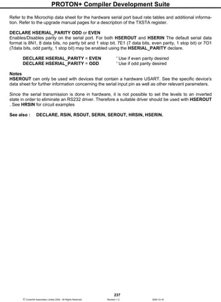

![PROTON+ Compiler Development Suite
243
Crownhill Associates Limited 2004 - All Rights Reserved Revision 1.2 2004-10-18
INKEY
Syntax
Variable = INKEY
Overview
Scan a keypad and place the returned value into variable
Operators
Variable is a user defined variable
Example
DIM VAR1 AS BYTE
VAR1 = INKEY ' Scan the keypad
DELAYMS 50 ' Debounce by waiting 50ms
PRINT DEC VAR1 , " " ' Display the result on the LCD
Notes
INKEY will return a value between 0 and 16. If no key is pressed, the value returned is 16.
Using a LOOKUP command, the returned values can be re-arranged to correspond with the legends
printed on the keypad: -
VAR1 = INKEY
KEY = LOOKUP VAR1, [255,1,4,7,"*",2,5,8,0,3,6,9,"#",0,0,0]
The above example is only a demonstration, the values inside the LOOKUP command will need to be
re-arranged for the type of keypad used, and it's connection configuration.
Declare
DECLARE KEYPAD_PORT PORT
Assigns the Port that the keypad is attached to.
The keypad routine requires pull-up resistors, therefore, the best Port for this device is PORTB, which
comes equipped with internal pull-ups. If the DECLARE is not used in the program, then PORTB is the
default Port.
The diagram illustrates a typical
connection of a 12-button key-
pad to a PIC16F84. If a 16-
button type is used, then COL-
UMN 4 will connect to PORTB.7
(RB7).
RB7VDD
RB6
RB5
RB4
RB3
RB2
RB1
RB0
13
RA4
RA3
RA2
RA1
RA0
MCLR
OSC1
OSC2
VSS
14
PIC16F84
C4
22pf
C1
10uf
C2
0.1uf
R1
4.7k
+5 Volts
C3
22pf
4MHz
Crystal
12
11
10
9
8
7
6
3
2
1
18
17
5
4
16
15
0v
1 2 3
654
7 8 9
0 #*
R2-R5
470
COLUMNS
R
O
W
S](https://image.slidesharecdn.com/protondsuserguide-150604211022-lva1-app6891/85/Proton-ds-userguide-245-320.jpg)
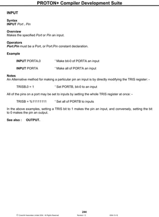
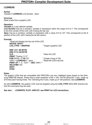
![PROTON+ Compiler Development Suite
246
Crownhill Associates Limited 2004 - All Rights Reserved Revision 1.2 2004-10-18
LCDWRITE
Syntax
LCDWRITE Line number , Xpos , [ Value ,{ Value etc…} ]
Overview
Write a byte to a graphic LCD.
Operators
Line Number may be a constant, variable or expression within the range of 0 to 7. This corresponds
to the line number of the LCD, with 0 being the top row.
Xpos may be a constant, variable or expression within the value of 0 to 127. This corresponds to the X
position of the LCD, with 0 being the far left column.
Value may be a constant, variable, or expression, within the range of 0 to 255 (byte).
Example
'Display a line on the top row of the LCD
DEVICE 16F877
LCD_TYPE = GRAPHIC ' Target a graphic LCD
DIM XPOS AS BYTE
CLS ' Clear the LCD
FOR XPOS = 0 TO 127 ' Create a loop of 128
LCDWRITE 0 , XPOS, [%00001111 ] ' Write to the LCD's top line
DELAYMS 100
NEXT
STOP
Notes
The graphic LCDs that are compatible with PROTON+ are non-intelligent types based on the Sam-
sung S6B0108 chipset. These have a pixel resolution of 64 x 128. The 64 being the Y axis, made up
of 8 lines each having 8-bits. The 128 being the X axis, made up of 128 positions. See below: -
The diagram illustrates the position of one byte at
position 0,0 on the LCD screen. The least signifi-
cant bit is located at the top. The byte displayed
has a value of 149 (10010101).
See also : LCDREAD, PLOT, UNPLOT, see
PRINT for LCD connections.
Xpos 0 - 127
Ypos0-63
lsb
Line 0
Line 1
Line 2
Line 3
msb](https://image.slidesharecdn.com/protondsuserguide-150604211022-lva1-app6891/85/Proton-ds-userguide-248-320.jpg)
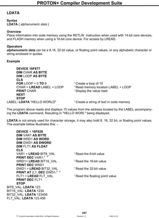
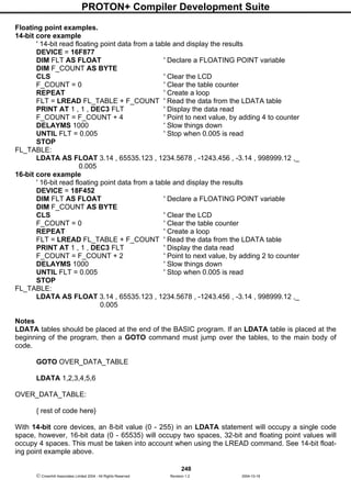
![PROTON+ Compiler Development Suite
250
Crownhill Associates Limited 2004 - All Rights Reserved Revision 1.2 2004-10-18
DWORD will force the value to occupy 4 bytes of code space, regardless of its value. Any value below
65535 will be padded to bring the memory count to 4 bytes. The line of code shown above uses the
DWORD formatter to ensure all the values in the LDATA table occupy 4 bytes of code space.
FLOAT will force a value to its floating point equivalent, which always takes up 4 bytes of code space.
If all the values in an LDATA table are required to occupy the same amount of bytes, then a single
formatter will ensure that this happens.
LDATA AS DWORD 100000 , 10000 , 1000 , 100 , 10 , 1
The above line has the same effect as the formatter previous example using separate DWORD for-
matters, in that all values will occupy 4 bytes, regardless of their value. All four formatters can be used
with the AS keyword.
The example below illustrates the formatters in use.
' Convert a DWORD value into a string array using only BASIC commands
' Similar principle to the STR$ command
INCLUDE "PROTON_4.INC"
DIM P10 AS DWORD ' Power of 10 variable
DIM CNT AS BYTE
DIM J AS BYTE
DIM VALUE AS BYTE ' Value to convert
DIM STRING1[11] AS BYTE ' Holds the converted value
DIM PTR AS BYTE ' Pointer within the Byte array
DELAYMS 500 ' Wait for PICmicro to stabilise
CLS ' Clear the LCD
Clear ' Clear all RAM before we start
VALUE = 1234576 ' Value to convert
GOSUB DWORD_TO_STR ' Convert VALUE to string
PRINT STR STRING1 ' Display the result
Stop
'-------------------------------------------------------------
' Convert a DWORD value into a string array. Value to convert is placed in 'VALUE'
' Byte array 'STRING1' is built up with the ASCII equivalent
DWORD_TO_STR:
PTR = 0
J = 0
REPEAT
P10 = LREAD DWORD_TBL + (J * 4)
CNT = 0
WHILE VALUE >= P10
VALUE = VALUE - P10
INC CNT
WEND
IF CNT <> 0 THEN
STRING1[PTR] = CNT + "0"](https://image.slidesharecdn.com/protondsuserguide-150604211022-lva1-app6891/85/Proton-ds-userguide-252-320.jpg)
![PROTON+ Compiler Development Suite
251
Crownhill Associates Limited 2004 - All Rights Reserved Revision 1.2 2004-10-18
INC PTR
ENDIF
INC J
UNTIL J > 8
STRING1[PTR] = VALUE + "0"
INC PTR
STRING1[PTR] = 0 ' Add the NULL to terminate the string
RETURN
' LDATA table is formatted for all 32 bit values.
' Which means each value will require 4 bytes of code space
DWORD_TBL:
LDATA AS DWORD 1000000000, 100000000, 10000000, 1000000, 100000, 10000, 1000, 100, 10
Label names as pointers.
If a label's name is used in the list of values in an LDATA table, the label's address will be used. This
is useful for accessing other tables of data using their address from a lookup table. See example be-
low.
' Display text from two LDATA tables
' Based on their address located in a separate table
INCLUDE "PROTON_4.INC" ' Use a 14-bit core device
DIM ADDRESS AS WORD
DIM DATA_BYTE AS BYTE
DELAYMS 200 ' Wait for PICmicro to stabilise
CLS ' Clear the LCD
ADDRESS = LREAD ADDR_TABLE ' Locate the address of the first string
WHILE 1 = 1 ' Create an infinite loop
DATA_BYTE = LREAD ADDRESS ' Read each character from the LDATA string
IF DATA_BYTE = 0 THEN EXIT_LOOP ' Exit if NULL found
PRINT DATA_BYTE ' Display the character
INC ADDRESS ' Next character
WEND ' Close the loop
EXIT_LOOP:
CURSOR 2,1 ' Point to line 2 of the LCD
ADDRESS = LREAD ADDR_TABLE + 2 ' Locate the address of the second string
WHILE 1 = 1 ' Create an infinite loop
DATA_BYTE = LREAD ADDRESS ' Read each character from the LDATA string
IF DATA_BYTE = 0 THEN EXIT_LOOP2 ' Exit if NULL found
PRINT DATA_BYTE ' Display the character
INC ADDRESS ' Next character
WEND ' Close the loop
EXIT_LOOP2:
STOP
ADDR_TABLE: ' Table of address's
LDATA AS WORD STRING1, STRING2
STRING1:
LDATA "HELLO",0
STRING2:
LDATA "WORLD",0
See also : CDATA, CREAD, DATA, EDATA, LREAD, READ, RESTORE.](https://image.slidesharecdn.com/protondsuserguide-150604211022-lva1-app6891/85/Proton-ds-userguide-253-320.jpg)
![PROTON+ Compiler Development Suite
252
Crownhill Associates Limited 2004 - All Rights Reserved Revision 1.2 2004-10-18
LET
Syntax
[LET] Variable = Expression
Overview
Assigns an expression, command result, variable, or constant, to a variable
Operators
Variable is a user defined variable.
Expression is one of many options - these can be a combination of variables, expressions, and num-
bers or other command calls.
Example 1
LET A = 1
A = 1
Both the above statements are the same
Example 2
A = B + 3
Example 3
A = A << 1
Example 4
LET B = EREAD C + 8
Notes
The LET command is optional, and is a leftover from earlier BASICs.
See also : DIM, SYMBOL.](https://image.slidesharecdn.com/protondsuserguide-150604211022-lva1-app6891/85/Proton-ds-userguide-254-320.jpg)
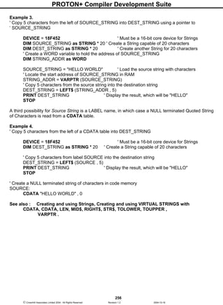
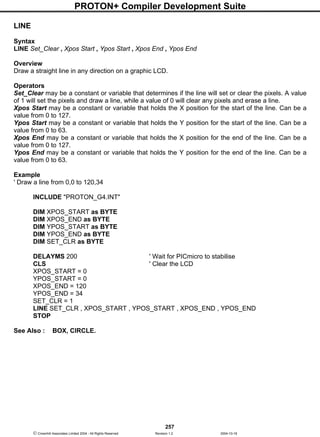
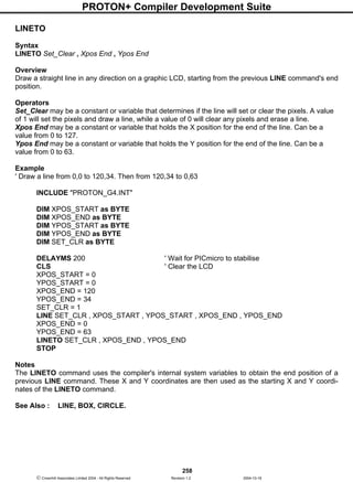
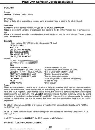
![PROTON+ Compiler Development Suite
260
Crownhill Associates Limited 2004 - All Rights Reserved Revision 1.2 2004-10-18
LOOKDOWN
Syntax
Variable = LOOKDOWN Index , [ Constant { , Constant…etc } ]
Overview
Search constants(s) for index value. If index matches one of the constants, then store the matching
constant's position (0-N) in variable. If no match is found, then the variable is unaffected.
Operators
Variable is a user define variable that holds the result of the search.
Index is the variable/constant being sought.
Constant(s),... is a list of values. A maximum of 255 values may be placed between the square
brackets, 256 if using a 16-bit core device.
Example
DIM Value AS BYTE
DIM Result AS BYTE
Value = 177 ' The value to look for in the list
Result = 255 ' Default to value 255
Result = LOOKDOWN Value , [75,177,35,1,8,29,245]
PRINT "Value matches " , DEC Result , " in list"
In the above example, PRINT displays, "Value matches 1 in list" because VALUE (177) matches item
1 of [75,177,35,1,8,29,245]. Note that index numbers count up from 0, not 1; that is in the list
[75,177,35,1,8,29,245], 75 is item 0.
If the value is not in the list, then RESULT is unchanged.
Notes
LOOKDOWN is similar to the index of a book. You search for a topic and the index gives you the page
number. Lookdown searches for a value in a list, and stores the item number of the first match in a
variable.
LOOKDOWN also supports text phrases, which are basically lists of byte values, so they are also eli-
gible for Lookdown searches:
DIM Value AS BYTE
DIM Result AS BYTE
Value = 101 ' ASCII "e". the value to look for in the list
Result = 255 ' Default to value 255
Result = LOOKDOWN Value , ["Hello World"]
In the above example, RESULT will hold a value of 1, which is the position of character 'e'
See also : CDATA, CREAD, DATA, EDATA, EREAD, LDATA, LOOKDOWNL, LOOKUP,
LOOKUPL, LREAD, READ, RESTORE.](https://image.slidesharecdn.com/protondsuserguide-150604211022-lva1-app6891/85/Proton-ds-userguide-262-320.jpg)
![PROTON+ Compiler Development Suite
261
Crownhill Associates Limited 2004 - All Rights Reserved Revision 1.2 2004-10-18
LOOKDOWNL
Syntax
Variable = LOOKDOWNL Index , {Operator} [ Value { , Value…etc } ]
Overview
A comparison is made between index and value; if the result is true, 0 is written into variable. If that
comparison was false, another comparison is made between value and value1; if the result is true, 1 is
written into variable. This process continues until a true is yielded, at which time the index is written
into variable, or until all entries are exhausted, in which case variable is unaffected.
Operators
Variable is a user define variable that holds the result of the search.
Index is the variable/constant being sought.
Value(s) can be a mixture of 16-bit constants, string constants and variables. Expressions may not be
used in the Value list, although they may be used as the index value. A maximum of 85 values may be
placed between the square brackets, 256 if using a 16-bit core device.
Operator is an optional comparison operator and may be one of the following: -
= equal
<> not equal
> greater than
< less than
>= greater than or equal to
<= less than or equal to
The optional operator can be used to perform a test for other than equal to ("=") while searching the
list. For example, the list could be searched for the first Value greater than the index parameter by
using ">" as the operator. If operator is left out, "=" is assumed.
Example
VAR1 = LOOKDOWNL WRD , [ 512 , WRD1, 1024 ]
VAR1 = LOOKDOWNL WRD , < [ 10 , 100 , 1000 ]
Notes
Because LOOKDOWNL is more versatile than the standard LOOKDOWN command, it generates lar-
ger code. Therefore, if the search list is made up only of 8-bit constants and strings, use LOOK-
DOWN.
See also : CDATA, CREAD, DATA, EDATA, EREAD, LDATA, LOOKDOWN, LOOKUP,
LOOKUPL, LREAD, READ, RESTORE.](https://image.slidesharecdn.com/protondsuserguide-150604211022-lva1-app6891/85/Proton-ds-userguide-263-320.jpg)
![PROTON+ Compiler Development Suite
262
Crownhill Associates Limited 2004 - All Rights Reserved Revision 1.2 2004-10-18
LOOKUP
Syntax
Variable = LOOKUP Index , [ Constant { , Constant…etc } ]
Overview
Look up the value specified by the index and store it in variable. If the index exceeds the highest index
value of the items in the list, then variable remains unchanged.
Operators
Variable may be a constant, variable, or expression. This is where the retrieved value will be stored.
Index may be a constant of variable. This is the item number of the value to be retrieved from the list.
Constant(s) may be any 8-bit value (0-255). A maximum of 255 values may be placed between the
square brackets, 256 if using a 16-bit core device.
Example
' Create an animation of a spinning line.
DIM INDEX AS BYTE
DIM Frame AS BYTE
CLS ' Clear the LCD
Rotate:
FOR INDEX = 0 TO 3 ' Create a loop of 4
Frame = LOOKUP INDEX , [ "|-/" ] ' Table of animation characters
PRINT AT 1 , 1 , Frame ' Display the character
DELAYMS 200 ' So we can see the animation
NEXT ' Close the loop
GOTO Rotate ' Repeat forever
Notes
index starts at value 0. For example, in the LOOKUP command below. If the first value (10) is re-
quired, then index will be loaded with 0, and 1 for the second value (20) etc.
VAR1 = LOOKUP INDEX , [ 10 , 20 , 30 ]
See also : CDATA, CREAD, DATA, EDATA, EREAD, LDATA, LOOKDOWN,
LOOKDOWNL, LOOKUPL, LREAD, READ, RESTORE.](https://image.slidesharecdn.com/protondsuserguide-150604211022-lva1-app6891/85/Proton-ds-userguide-264-320.jpg)
![PROTON+ Compiler Development Suite
263
Crownhill Associates Limited 2004 - All Rights Reserved Revision 1.2 2004-10-18
LOOKUPL
Syntax
Variable = LOOKUPL Index , [ Value { , Value…etc } ]
Overview
Look up the value specified by the index and store it in variable. If the index exceeds the highest index
value of the items in the list, then variable remains unchanged. Works exactly the same as LOOKUP,
but allows variable types or constants in the list of values.
Operators
Variable may be a constant, variable, or expression. This is where the retrieved value will be stored.
Index may be a constant of variable. This is the item number of the value to be retrieved from the list.
Value(s) can be a mixture of 16-bit constants, string constants and variables. A maximum of 85 values
may be placed between the square brackets, 256 if using a 16-bit core device.
Example
DIM VAR1 AS BYTE
DIM WRD AS WORD
DIM INDEX AS BYTE
DIM Assign AS WORD
VAR1 = 10
WRD = 1234
INDEX = 0 ' Point to the first value in the list (WRD)
Assign = LOOKUPL INDEX , [ WRD , VAR1 , 12345 ]
Notes
Expressions may not be used in the Value list, although they may be used as the Index value.
Because LOOKUPL is capable of processing any variable and constant type, the code produced is a
lot larger than that of LOOKUP. Therefore, if only 8-bit constants are required in the list, use LOOKUP
instead.
See also : CDATA, CREAD, DATA, EDATA, EREAD, LDATA, LOOKDOWN,
LOOKDOWNL, LOOKUP, LREAD, READ, RESTORE.](https://image.slidesharecdn.com/protondsuserguide-150604211022-lva1-app6891/85/Proton-ds-userguide-265-320.jpg)
![PROTON+ Compiler Development Suite
268
Crownhill Associates Limited 2004 - All Rights Reserved Revision 1.2 2004-10-18
LREAD8, LREAD16, LREAD32
Syntax
Variable = LREAD8 Label [ Offset Variable ]
or
Variable = LREAD16 Label [ Offset Variable ]
or
Variable = LREAD32 Label [ Offset Variable ]
Overview
Read an 8, 16, or 32-bit value from an LDATA table using an offset of Offset Variable and place into
Variable, with more efficiency than using LREAD . For PICmicro’s that can access their own code
memory, such as the 16F87x and all the 18F range.
LREAD8 will access 8-bit values from an LDATA table.
LREAD16 will access 16-bit values from an LDATA table.
LREAD32 will access 32-bit values from an LDATA table, this also includes floating point values.
Operators
Variable is a user defined variable of type BIT, BYTE, BYTE_ARRAY, WORD, WORD_ARRAY,
DWORD, or FLOAT.
Label is a label name preceding the LDATA statement of which values will be read from.
Offset Variable can be a constant value, variable, or expression that points to the location of interest
within the LDATA table.
LREAD8 Example
' Extract the second value from within an 8-bit LDATA table
DEVICE = 16F877
DIM OFFSET AS BYTE ' Declare a BYTE size variable for the offset
DIM RESULT AS BYTE ' Declare a BYTE size variable to hold the result
CLS ' Clear the LCD
OFFSET = 1 ' Point to the second value in the LDATA table
' Read the 8-bit value pointed to by OFFSET
RESULT = LREAD8 BYTE_TABLE [OFFSET]
PRINT DEC RESULT ' Display the decimal result on the LCD
STOP
' Create a table containing only 8-bit values
BYTE_TABLE: LDATA AS BYTE 100 , 200](https://image.slidesharecdn.com/protondsuserguide-150604211022-lva1-app6891/85/Proton-ds-userguide-270-320.jpg)
![PROTON+ Compiler Development Suite
269
Crownhill Associates Limited 2004 - All Rights Reserved Revision 1.2 2004-10-18
LREAD16 Example
' Extract the second value from within a 16-bit LDATA table
DEVICE = 16F877
DIM OFFSET AS BYTE ' Declare a BYTE size variable for the offset
DIM RESULT AS WORD ' Declare a WORD size variable to hold the result
CLS ' Clear the LCD
OFFSET = 1 ' Point to the second value in the LDATA table
' Read the 16-bit value pointed to by OFFSET
RESULT = LREAD16 WORD_TABLE [OFFSET]
PRINT DEC RESULT ' Display the decimal result on the LCD
STOP
' Create a table containing only 16-bit values
WORD_TABLE: LDATA AS WORD 1234 , 5678
LREAD32 Example
' Extract the second value from within a 32-bit LDATA table
DEVICE = 16F877
DIM OFFSET AS BYTE ' Declare a BYTE size variable for the offset
DIM RESULT AS DWORD ' Declare a DWORD size variable to hold the result
CLS ' Clear the LCD
OFFSET = 1 ' Point to the second value in the LDATA table
' Read the 32-bit value pointed to by OFFSET
RESULT = LREAD32 DWORD_TABLE [OFFSET]
PRINT DEC RESULT ' Display the decimal result on the LCD
STOP
' Create a table containing only 32-bit values
DWORD_TABLE: LDATA AS DWORD 12340 , 56780
Notes
Data storage in any program is of paramount importance, and although the standard LREAD com-
mand can access multi-byte values from an LDATA table, it was not originally intended as such, and
is more suited to accessing character data or single 8-bit values. However, the LREAD8, LREAD16,
and LREAD32 commands are specifically written in order to efficiently read data from an LDATA ta-
ble, and use the least amount of code space in doing so, thus increasing the speed of operation.
Which means that wherever possible, LREAD should be replaced by LREAD8, LREAD16, or
LREAD32.
See also : CDATA, CREAD, DATA, LDATA, LREAD, READ, RESTORE .](https://image.slidesharecdn.com/protondsuserguide-150604211022-lva1-app6891/85/Proton-ds-userguide-271-320.jpg)
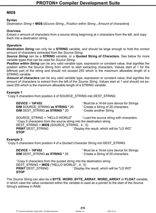
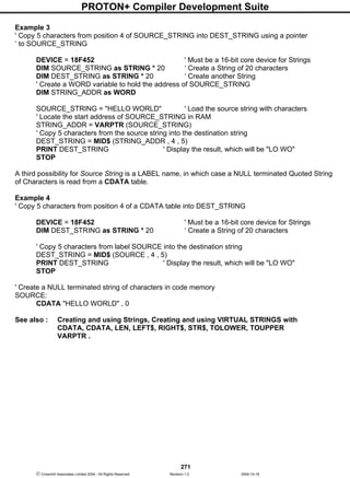
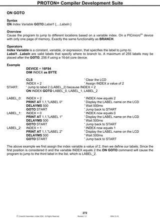
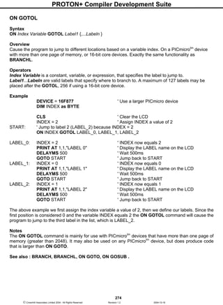
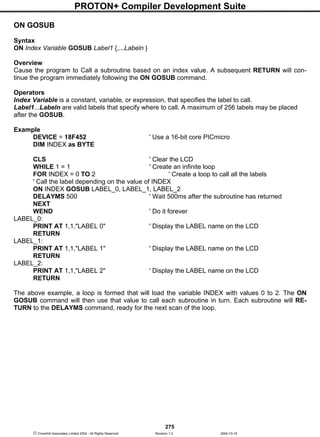
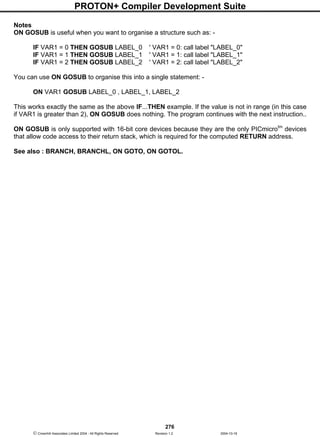
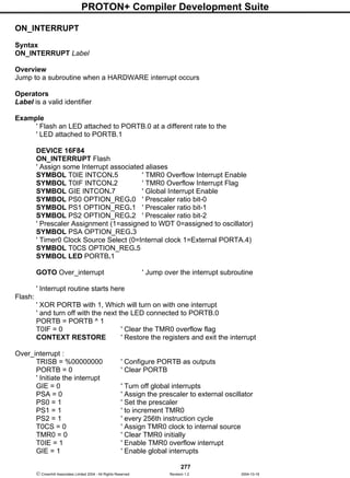
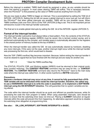
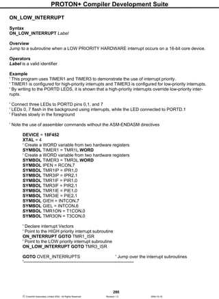
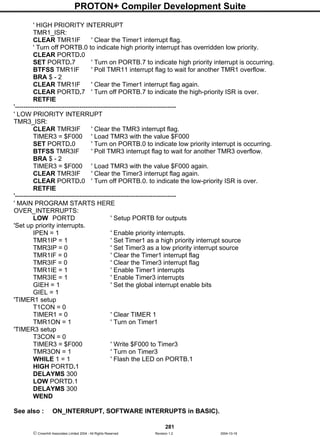
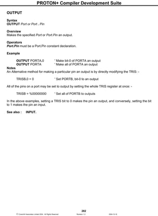
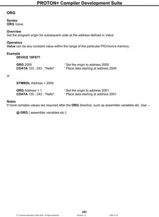
![PROTON+ Compiler Development Suite
284
Crownhill Associates Limited 2004 - All Rights Reserved Revision 1.2 2004-10-18
OREAD
Syntax
OREAD Pin , Mode , [ Inputdata ]
Overview
Receive data from a device using the Dallas Semiconductor 1-wire protocol. The 1-wire protocol is a
form of asynchronous serial communication developed by Dallas Semiconductor. It requires only one
I/O pin which may be shared between multiple 1-wire devices.
Operators
Pin is a PORT-BIT combination that specifies which I/O pin to use. 1-wire devices require only one I/O
pin (normally called DQ) to communicate. This I/O pin will be toggled between output and input mode
during the OREAD command and will be set to input mode by the end of the OREAD command.
Mode is a numeric constant (0 - 7) indicating the mode of data transfer. The Mode argument control's
the placement of reset pulses and detection of presence pulses, as well as byte or bit input. See notes
below.
Inputdata is a list of variables or arrays to store the incoming data into.
Example
DIM Result AS BYTE
SYMBOL DQ = PORTA.0
OREAD DQ, 1 , [ Result ]
The above example code will transmit a 'reset' pulse to a 1-wire device (connected to bit 0 of PORTA)
and will then detect the device's 'presence' pulse and receive one byte and store it in the variable Re-
sult.
Notes
The Mode operator is used to control placement of reset pulses (and detection of presence pulses)
and to designate byte or bit input. The table below shows the meaning of each of the 8 possible value
combinations for Mode.
The correct value for Mode depends on the 1-wire device and the portion of the communication that is
being dealt with. Consult the data sheet for the device in question to determine the correct value for
Mode. In many cases, however, when using the OREAD command, Mode should be set for either No
Reset (to receive data from a transaction already started by an OWRITE
Mode
Value
Effect
0 No Reset, Byte mode
1 Reset before data, Byte mode
2 Reset after data, Byte mode
3 Reset before and after data, Byte mode
4 No Reset, Bit mode
5 Reset before data, Bit mode
6 Reset after data, Bit mode
7 Reset before and after data, Bit mode](https://image.slidesharecdn.com/protondsuserguide-150604211022-lva1-app6891/85/Proton-ds-userguide-286-320.jpg)
![PROTON+ Compiler Development Suite
285
Crownhill Associates Limited 2004 - All Rights Reserved Revision 1.2 2004-10-18
command) or a Reset after data (to terminate the session after data is received). However, this may
vary due to device and application requirements.
When using the Bit (rather than Byte) mode of data transfer, all variables in the InputData argument
will only receive one bit. For example, the following code could be used to receive two bits using this
mode: -
DIM BitVar1 AS BIT
DIM BitVar2 AS BIT
OREAD PORTA.0 , 6 , [ BitVar1, BitVar2 ]
In the example code shown, a value of 6 was chosen for Mode. This sets Bit transfer and Reset after
data mode.
We could also have chosen to make the BitVar1 and BitVar2 variables each a BYTE type, however,
they would still only have received one bit each in the OREAD command, due to the Mode that was
chosen.
The compiler also has a modifier for handling a string of data, named STR.
The STR modifier is used for receiving data and placing it directly into a byte array variable.
A string is a set of bytes that are arranged or accessed in a certain order. The values 1, 2, 3 would be
stored in a string with the value 1 first, followed by 2 then followed by the value 3. A byte array is a
similar concept to a string; it contains data that is arranged in a certain order. Each of the elements in
an array is the same size. The string 1 2 3 would be stored in a byte array containing three bytes
(elements).
Below is an example that receives ten bytes through a 1-wire interface and stores them in the 10-byte
array, MYARRAY: -
DIM MyArray[10] AS BYTE ' Create a 10-byte array.
OREAD DQ, 1 , [STR MyArray]
PRINT DEC STR MyArray ' Display the values.
If the amount of received characters is not enough to fill the entire array, then a formatter may be
placed after the array's name, which will only receive characters until the specified length is reached.
For example: -
DIM MyArray[10] AS BYTE ' Create a 10-byte array.
OREAD DQ, 1 , [ STR MyArray 5 ] ' Fill the first 5-bytes of the array with
' received data.
PRINT STR MyArray 5 ' Display the 5-value string.
The example above illustrates how to fill only the first n bytes of an array, and then how to display only
the first n bytes of the array. n refers to the value placed after the backslash.](https://image.slidesharecdn.com/protondsuserguide-150604211022-lva1-app6891/85/Proton-ds-userguide-287-320.jpg)
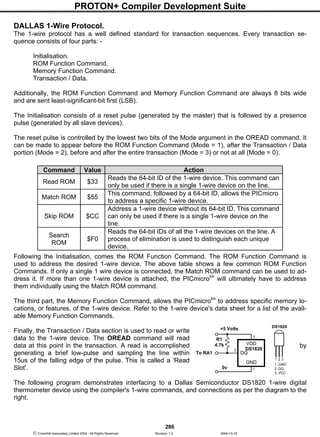
![PROTON+ Compiler Development Suite
287
Crownhill Associates Limited 2004 - All Rights Reserved Revision 1.2 2004-10-18
The code reads the Counts Remaining and Counts per Degree Centigrade registers within the
DS1820 device in order to provide a more accurate temperature (down to 1/10th of a degree).
DEVICE 16F84
DECLARE XTAL 4
SYMBOL DQ = PortA.1 ' Place the DS1820 on bit-1 of PORTA
DIM Temp AS WORD ' Holds the temperature value
DIM C AS BYTE ' Holds the counts remaining value
DIM CPerD AS BYTE ' Holds the Counts per degree C value
CLS ' Clear the LCD before we start
Again:
OWRITE DQ, 1, [$CC, $44] ' Send Calculate Temperature command
REPEAT
DELAYMS 25 ' Wait until conversion is complete
OREAD DQ, 4, [C] ' Keep reading low pulses until
UNTIL C <> 0 ' the DS1820 is finished.
OWRITE DQ, 1, [$CC, $BE] ' Send Read ScratchPad command
OREAD DQ, 2,[Temp.LOWBYTE,Temp.HIGHBYTE, C, C, C, C, C, CPerD]
' Calculate the temperature in degrees Centigrade
Temp = (((Temp >> 1) * 100) - 25) + (((CPerD - C) * 100) / CPerD)
PRINT AT 1,1, DEC Temp / 100, ".", DEC2 Temp," ", AT 1,8,"C"
GOTO Again
Note. The equation used in the program above will not work correctly with negative temperatures. Also
note that the 4.7kΩ pull-up resistor (R1) is required for correct operation.
Inline OREAD Command.
The standard structure of the OREAD command is: -
OREAD Pin , Mode , [ Inputdata ]
However, this did not allow it to be used in conditions such as IF-THEN, WHILE-WEND etc. Therefore,
there is now an additional structure to the OREAD command: -
Var = OREAD Pin , Mode
Operands Pin and Mode have not changed their function, but the result from the 1-wire read is now
placed directly into the assignment variable.](https://image.slidesharecdn.com/protondsuserguide-150604211022-lva1-app6891/85/Proton-ds-userguide-289-320.jpg)
![PROTON+ Compiler Development Suite
288
Crownhill Associates Limited 2004 - All Rights Reserved Revision 1.2 2004-10-18
OREAD - OWRITE Presence Detection.
Another important feature to both the OREAD and OWRITE commands is the ability to jump to a sec-
tion of the program if a presence is not detected on the 1-wire bus.
OWRITE Pin , Mode , Label , [ Outputdata ]
OREAD Pin , Mode , Label , [ Inputdata ]
Var = OREAD Pin , Mode, Label
The LABEL operand is an optional condition, but if used, it must reference a valid BASIC label.
' Skip ROM search & do temp conversion
OWRITE DQ, 1, NO_PRES, [$CC, $44]
WHILE OREAD DQ, 4, NO_PRES != 0 : WEND ' Read busy-bit,' Still busy..?
' Skip ROM search & read scratchpad memory
OWRITE DQ, 1, NO_PRES, [$CC, $BE]
OREAD DQ, 2, NO_PRES, [Temp.Lowbyte, Temp.Highbyte] ' Read two bytes
RETURN
NO_PRES:
PRINT "No Presence"
STOP
See also : OWRITE.](https://image.slidesharecdn.com/protondsuserguide-150604211022-lva1-app6891/85/Proton-ds-userguide-290-320.jpg)
![PROTON+ Compiler Development Suite
289
Crownhill Associates Limited 2004 - All Rights Reserved Revision 1.2 2004-10-18
OWRITE
Syntax
OWRITE Pin , Mode , [ Outputdata ]
Overview
Send data to a device using the Dallas Semiconductor 1-wire protocol. The 1-wire protocol is a form of
asynchronous serial communication developed by Dallas Semiconductor. It requires only one I/O pin
which may be shared between multiple 1-wire d vices.
Operators
Pin is a PORT-BIT combination that specifies which I/O pin to use. 1-wire devices require only one I/O
pin (normally called DQ) to communicate. This I/O pin will be toggled between output and input mode
during the OWRITE command and will be set to input mode by the end of the OWRITE command.
Mode is a numeric constant (0 - 7) indicating the mode of data transfer. The Mode operator control's
the placement of reset pulses and detection of presence pulses, as well as byte or bit input. See notes
below.
Outputdata is a list of variables or arrays transmit individual or repeating bytes.
Example
SYMBOL DQ = PORTA.0
OWRITE DQ, 1 , [ $4E ]
The above example will transmit a 'reset' pulse to a 1-wire device (connected to bit 0 of PORTA) and
will then detect the device's 'presence' pulse and transmit one byte (the value $4E).
Notes
The Mode operator is used to control placement of reset pulses (and detection of presence pulses)
and to designate byte or bit input. The table below shows the meaning of each of the 8 possible value
combinations for Mode.
The correct value for Mode depends on the 1-wire device and the portion of the communication you're
dealing with. Consult the data sheet for the device in question to determine the correct value for Mode.
In many cases, however, when using the OWRITE command, Mode should be set for a Reset before
data (to initialise the transaction). However, this may vary due to device and application requirements.
Mode
Value
Effect
0 No Reset, Byte mode
1 Reset before data, Byte mode
2 Reset after data, Byte mode
3 Reset before and after data, Byte mode
4 No Reset, Bit mode
5 Reset before data, Bit mode
6 Reset after data, Bit mode
7 Reset before and after data, Bit mode](https://image.slidesharecdn.com/protondsuserguide-150604211022-lva1-app6891/85/Proton-ds-userguide-291-320.jpg)
![PROTON+ Compiler Development Suite
290
Crownhill Associates Limited 2004 - All Rights Reserved Revision 1.2 2004-10-18
When using the Bit (rather than Byte) mode of data transfer, all variables in the InputData argument
will only receive one bit. For example, the following code could be used to receive two bits using this
mode: -
DIM BitVar1 AS BIT
DIM BitVar2 AS BIT
OWRITE PORTA.0 , 6 , [ BitVar1, BitVar2 ]
In the example code shown, a value of 6 was chosen for Mode. This sets Bit transfer and Reset after
data mode. We could also have chosen to make the BitVar1 and BitVar2 variables each a BYTE type,
however, they would still only use their lowest bit (BIT0) as the value to transmit in the OWRITE com-
mand, due to the Mode value chosen.
The STR Modifier
The STR modifier is used for transmitting a string of bytes from a byte array variable. A string is a set
of bytes sized values that are arranged or accessed in a certain order. The values 1, 2, 3 would be
stored in a string with the value 1 first, followed by 2 then followed by the value 3. A byte array is a
similar concept to a string; it contains data that is arranged in a certain order. Each of the elements in
an array is the same size. The string 1,2,3 would be stored in a byte array containing three bytes
(elements).
Below is an example that sends four bytes (from a byte array) through bit-0 of PORTA: -
DIM MyArray[10] AS BYTE ' Create a 10-byte array.
MyArray [0] = $CC ' Load the first 4 bytes of the array
MyArray [1] = $44 ' With the data to send
MyArray [2] = $CC
MyArray [3] = $4E
OWRITE PORTA.0 , 1 , [ STR MyArray 4 ] ' Send 4-byte string.
Note that we use the optional n argument of STR. If we didn't specify this, the PICmicrotm
would try to
keep sending characters until all 10 bytes of the array were transmitted. Since we do not wish all 10
bytes to be transmitted, we chose to tell it explicitly to only send the first 4 bytes.
The above example may also be written as: -
DIM MyArray [10] AS BYTE ' Create a 10-byte array.
STR MyArray = $CC,$44,$CC,$4E ' Load the first 4 bytes of the array
OWRITE PORTA.0 , 1 , [ STR MyArray 4 ] ' Send 4-byte string.
The above example, has exactly the same function as the previous one. The only difference is that the
string is now constructed using the STR as a command instead of a modifier.
See also : OREAD for example code, and 1-wire protocol.](https://image.slidesharecdn.com/protondsuserguide-150604211022-lva1-app6891/85/Proton-ds-userguide-292-320.jpg)
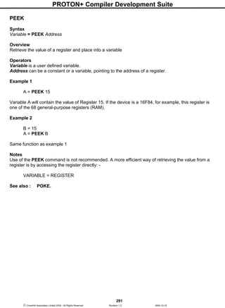
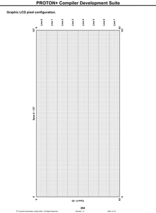
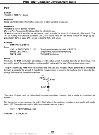
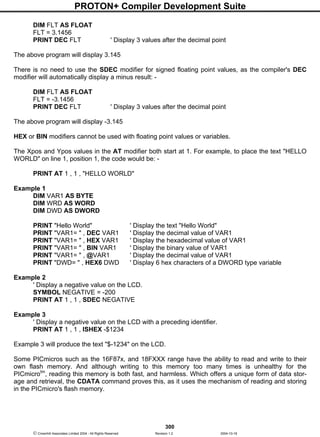
![PROTON+ Compiler Development Suite
302
Crownhill Associates Limited 2004 - All Rights Reserved Revision 1.2 2004-10-18
The STR modifier is used for sending a string of bytes from a byte array variable. A string is a set of
bytes sized values that are arranged or accessed in a certain order. The values 1, 2, 3 would be
stored in a string with the value 1 first, followed by 2 then followed by the value 3. A byte array is a
similar concept to a string; it contains data that is arranged in a certain order. Each of the elements in
an array is the same size. The string 1,2,3 would be stored in a byte array containing three bytes
(elements).
Below is an example that displays four bytes (from a byte array): -
DIM MYARRAY[10] AS BYTE ' Create a 10-byte array.
MYARRAY [0] = "H" ' Load the first 5 bytes of the array
MYARRAY [1] = "E" ' With the data to send
MYARRAY [2] = "L"
MYARRAY [3] = "L"
MYARRAY [4] = "O"
PRINT STR MYARRAY 5 ' Display a 5-byte string.
Note that we use the optional n argument of STR. If we didn't specify this, the PICmicrotm
would try to
keep sending characters until all 10 bytes of the array were transmitted. Since we do not wish all 10
bytes to be transmitted, we chose to tell it explicitly to only send the first 5 bytes.
The above example may also be written as: -
DIM MYARRAY [10] AS BYTE ' Create a 10-byte array.
STR MYARRAY = "HELLO" ' Load the first 5 bytes of the array
PRINT STR MYARRAY 5 ' Send 5-byte string.
The above example, has exactly the same function as the previous one. The only difference is that the
string is now constructed using STR as a command instead of a modifier.
Declares
There are six DECLARES for use with an alphanumeric LCD and PRINT: -
DECLARE LCD_TYPE 1 or 0 , GRAPHIC or ALPHA
Inform the compiler as to the type of LCD that the PRINT command will output to. If GRAPHIC or 1 is
chosen then any output by the PRINT command will be directed to a graphic LCD based on the Sam-
sung S6B0108 chipset. A value of 0 or ALPHA, or if the DECLARE is not issued will target the stan-
dard alphanumeric LCD type
Targeting the graphic LCD will also enable commands such as PLOT, UNPLOT, LCDREAD, and
LCDWRITE.
DECLARE LCD_DTPIN PORT . PIN
Assigns the Port and Pins that the LCD's DT (data) lines will attach to.
The LCD may be connected to the PICmicrotm
using either a 4-bit bus or an 8-bit bus. If an 8-bit bus is
used, all 8 bits must be on one port. If a 4-bit bus is used, it must be connected to either the bottom 4
or top 4 bits of one port. For example: -
DECLARE LCD_DTPIN PORTB.4 ' Used for 4-line interface.
DECLARE LCD_DTPIN PORTB.0 ' Used for 8-line interface.](https://image.slidesharecdn.com/protondsuserguide-150604211022-lva1-app6891/85/Proton-ds-userguide-304-320.jpg)
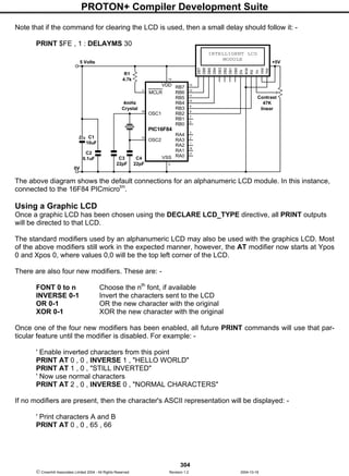
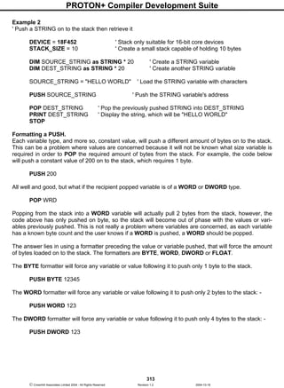
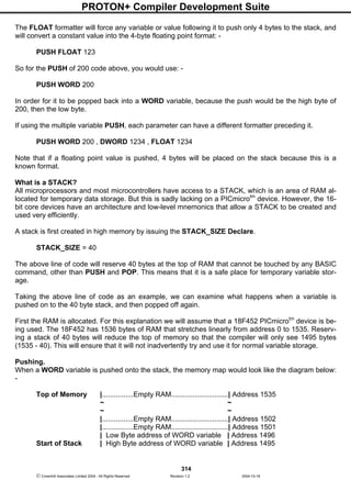
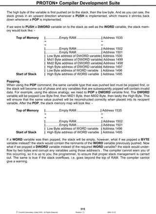

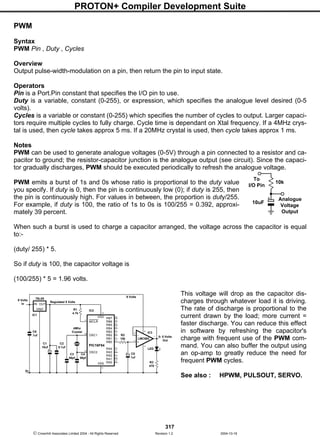
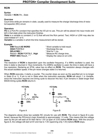


![PROTON+ Compiler Development Suite
328
Crownhill Associates Limited 2004 - All Rights Reserved Revision 1.2 2004-10-18
RETURN
Syntax
RETURN
or
RETURN Variable
Availability
All devices. But a parameter return is only supported with 16-bit core devices.
Overview
Return from a subroutine.
If using a 16-bit core device, a parameter can be pushed onto a software stack before the return mne-
monic is implemented.
Variable is a user defined variable of type BIT, BYTE, BYTE_ARRAY, WORD, WORD_ARRAY,
DWORD, FLOAT, or STRING, or constant value, that will be pushed onto the stack before the sub-
routine is exited.
Example
' Call a subroutine with parameters
DEVICE = 18F452 ' Stack only suitable for 16-bit core devices
STACK_SIZE = 20 ' Create a small stack capable of holding 20 bytes
DIM WRD1 as WORD ' Create a WORD variable
DIM WRD2 as WORD ' Create another WORD variable
DIM RECEIPT as WORD ' Create a variable to hold result
WRD1 = 1234 ' Load the WORD variable with a value
WRD2 = 567 ' Load the other WORD variable with a value
' Call the subroutine and return a value
GOSUB ADD_THEM [WRD1 , WRD2] , RECEIPT
PRINT DEC RECEIPT ' Display the result as decimal
STOP
' Subroutine starts here. Add the two parameters passed and return the result
ADD_THEM:
DIM ADD_WRD1 as WORD ' Create two uniquely named variables
DIM ADD_WRD2 as WORD
POP ADD_WRD2 ' Pop the last variable pushed
POP ADD_WRD1 ' Pop the first variable pushed
ADD_WRD1 = ADD_WRD1 + ADD_WRD2 ' Add the values together
RETURN ADD_WRD1 ' Return the result of the addition](https://image.slidesharecdn.com/protondsuserguide-150604211022-lva1-app6891/85/Proton-ds-userguide-330-320.jpg)
![PROTON+ Compiler Development Suite
335
Crownhill Associates Limited 2004 - All Rights Reserved Revision 1.2 2004-10-18
A variable preceded by BIN will receive the ASCII representation of its binary value.
For example, if BIN VAR1 is specified and "1000" is received, VAR1 will be set to 8.
A variable preceded by DEC will receive the ASCII representation of its decimal value.
For example, if DEC VAR1 is specified and "123" is received, VAR1 will be set to 123.
A variable preceded by HEX will receive the ASCII representation of its hexadecimal value.
For example, if HEX VAR1 is specified and "FE" is received, VAR1 will be set to 254.
SKIP followed by a count will skip that many characters in the input stream.
For example, SKIP 4 will skip 4 characters.
The RSIN command can be configured to wait for a specified sequence of characters before it re-
trieves any additional input. For example, suppose a device attached to the PICmicrotm
is known to
send many different sequences of data, but the only data you wish to observe happens to appear right
after the unique characters, "XYZ". A modifier named WAIT can be used for this purpose: -
RSIN WAIT( "XYZ" ) , SERDATA
The above code waits for the characters "X", "Y" and "Z" to be received, in that order, then it receives
the next data byte and places it into variable SERDATA.
STR modifier.
The RSIN command also has a modifier for handling a string of characters, named STR.
The STR modifier is used for receiving a string of characters into a byte array variable.
A string is a set of characters that are arranged or accessed in a certain order. The characters "ABC"
would be stored in a string with the "A" first, followed by the "B" then followed by the "C". A byte array
is a similar concept to a string; it contains data that is arranged in a certain order. Each of the ele-
ments in an array is the same size. The string "ABC" would be stored in a byte array containing three
bytes (elements).
Below is an example that receives ten bytes and stores them in the 10-byte array, SERSTRING: -
DIM SerString[10] AS BYTE ' Create a 10-byte array.
RSIN STR SerString ' Fill the array with received data.
PRINT STR SerString ' Display the string.
If the amount of received characters is not enough to fill the entire array, then a formatter may be
placed after the array's name, which will only receive characters until the specified length is reached.
For example: -
DIM SerString[10] AS BYTE ' Create a 10-byte array.
RSIN STR SerString5 ' Fill the first 5-bytes of the array
PRINT STR SerString5 ' Display the 5-character string.
The example above illustrates how to fill only the first n bytes of an array, and then how to display only
the first n bytes of the array. n refers to the value placed after the backslash.](https://image.slidesharecdn.com/protondsuserguide-150604211022-lva1-app6891/85/Proton-ds-userguide-337-320.jpg)

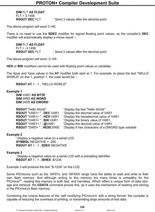
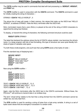
![PROTON+ Compiler Development Suite
340
Crownhill Associates Limited 2004 - All Rights Reserved Revision 1.2 2004-10-18
The values 1, 2, 3 would be stored in a string with the value 1 first, followed by 2 then followed by the
value 3. A byte array is a similar concept to a string; it contains data that is arranged in a certain order.
Each of the elements in an array is the same size. The string 1,2,3 would be stored in a byte array
containing three bytes (elements).
Below is an example that displays four bytes (from a byte array): -
DIM MYARRAY[10] AS BYTE ' Create a 10-byte array.
MYARRAY [0] = "H" ' Load the first 5 bytes of the array
MYARRAY [1] = "E" ' With the data to send
MYARRAY [2] = "L"
MYARRAY [3] = "L"
MYARRAY [4] = "O"
RSOUT STR MYARRAY 5 ' Display a 5-byte string.
Note that we use the optional n argument of STR. If we didn't specify this, the PICmicrotm
would try to
keep sending characters until all 10 bytes of the array were transmitted. Since we do not wish all 10
bytes to be transmitted, we chose to tell it explicitly to only send the first 5 bytes.
The above example may also be written as: -
DIM MYARRAY [10] AS BYTE ' Create a 10-byte array.
STR MYARRAY = "HELLO" ' Load the first 5 bytes of the array
RSOUT STR MYARRAY 5 ' Send 5-byte string.
The above example, has exactly the same function as the previous one. The only difference is that the
string is now constructed using STR as a command instead of a modifier.
Declares
There are four DECLARES for use with RSOUT. These are : -
DECLARE RSOUT_PIN PORT . PIN
Assigns the Port and Pin that will be used to output serial data from the RSOUT command. This may
be any valid port on the PICmicrotm
.
If the DECLARE is not used in the program, then the default Port and Pin is PORTB.0.
DECLARE RSOUT_MODE INVERTED , TRUE or 1 , 0
Sets the serial mode for the data transmitted by RSOUT. This may be inverted or true. Alternatively, a
value of 1 may be substituted to represent inverted, and 0 for true.
If the DECLARE is not used in the program, then the default mode is INVERTED.
DECLARE SERIAL_BAUD 0 to 65535 bps (baud)
Informs the RSIN and RSOUT routines as to what baud rate to receive and transmit data.
Virtually any baud rate may be transmitted and received, but there are standard bauds: -
300, 600, 1200, 2400, 4800, 9600, and 19200.](https://image.slidesharecdn.com/protondsuserguide-150604211022-lva1-app6891/85/Proton-ds-userguide-342-320.jpg)

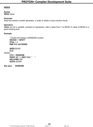
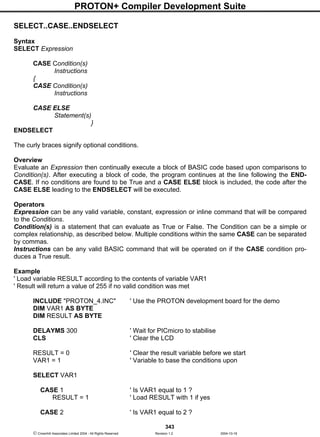
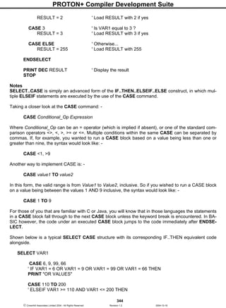
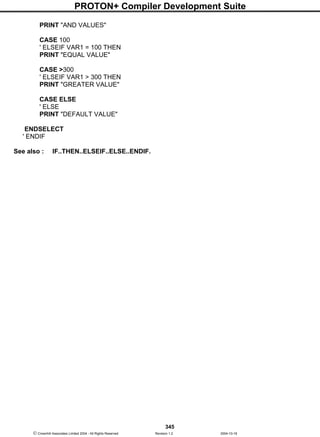
![PROTON+ Compiler Development Suite
346
Crownhill Associates Limited 2004 - All Rights Reserved Revision 1.2 2004-10-18
SERIN
Syntax
SERIN Rpin { Fpin } , Baudmode , { Plabel, } { Timeout , Tlabel, } [ InputData ]
Overview
Receive asynchronous serial data (i.e. RS232 data).
Operators
Rpin is a PORT.BIT constant that specifies the I/O pin through which the serial data will be received.
This pin will be set to input mode.
Fpin is an optional PORT.BIT constant that specifies the I/O pin to indicate flow control status on. This
pin will be set to output mode.
Baudmode may be a variable, constant, or expression (0 - 65535) that specifies serial timing and con-
figuration.
Plabel is an optional label indicating where the program should jump to in the event of a parity error.
This argument should only be provided if Baudmode indicates that parity is required.
Timeout is an optional constant (0 - 65535) that informs SERIN how long to wait for incoming data. If
data does not arrive in time, the program will jump to the address specified by Tlable.
Tlabel is an optional label that must be provided along with Timeout, indicating where the program
should go in the event that data does not arrive within the period specified by Timeout.
InputData is list of variables and modifiers that informs SERIN what to do with incoming data. SERIN
may store data in a variable, array, or an array string using the STR modifier.
Notes
One of the most popular forms of communication between electronic devices is serial communication.
There are two major types of serial communication; asynchronous and synchronous. The RSIN,
RSOUT, SERIN and SEROUT commands are all used to send and receive asynchronous serial data.
While the SHIN and SHOUT commands are for use with synchronous communications.
The term asynchronous means ‘no clock.’ More specifically, ‘asynchronous serial communication’
means data is transmitted and received without the use of a separate ‘clock’ line. Data can be sent us-
ing as few as two wires; one for data and one for ground. The PC's serial ports (also called COM ports
or RS232 ports) use asynchronous serial communication. Note: the other kind of serial communica-
tion, synchronous, uses at least three wires; one for clock, one for data and one for ground.
RS232 is the electrical specification for the signals that PC serial ports use. Unlike standard TTL logic,
where 5 volts is a logic 1 and 0 volts is logic 0, RS232 uses -12 volts for logic 1 and +12 volts for logic
0. This specification allows communication over longer wire lengths without amplification.
Most circuits that work with RS232 use a line driver / receiver (transceiver). This component does two
things: -
Convert the ±12 volts of RS-232 to TTL compatible 0 to 5 volt levels.
Invert the voltage levels, so that 5 volts = logic 1 and 0 volts = logic 0.
By far, the most common line driver device is the MAX232 from Maxim semiconductor. With the addi-
tion of a few capacitors, a complete 2-way level converter is realised. Figure 1 shows a typical circuit
for one of these devices. The MAX232 is not the only device available, there are](https://image.slidesharecdn.com/protondsuserguide-150604211022-lva1-app6891/85/Proton-ds-userguide-348-320.jpg)
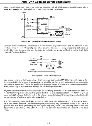

![PROTON+ Compiler Development Suite
349
Crownhill Associates Limited 2004 - All Rights Reserved Revision 1.2 2004-10-18
Declaring SERIAL_DATA as 9 allows 8 bits to be read and written along with a 9th
parity bit.
Parity is a simple error-checking feature. When a serial sender is set for even parity (the mode the
compiler supports) it counts the number of 1s in an outgoing byte and uses the parity bit to make that
number even. For example, if it is sending the 7-bit value: %0011010, it sets the parity bit to 1 in order
to make an even number of 1s (four).
The receiver also counts the data bits to calculate what the parity bit should be. If it matches the parity
bit received, the serial receiver assumes that the data was received correctly. Of course, this is not
necessarily true, since two incorrectly received bits could make parity seem correct when the data was
wrong, or the parity bit itself could be bad when the rest of the data was correct.
Many systems that work exclusively with text use 7-bit/ even-parity mode. For example, to receive one
data byte through bit-0 of PORTA at 9600 baud, 7E, inverted:
SERIN PORTA.0 , 24660 , [SerData]
The above example will work correctly, however it doesn’t inform the program what to do in the event
of a parity error.
Below, is an improved version that uses the optional Plabel argument:
SERIN PORTA.0 , 24660 , P_ERROR , [SerData]
PRINT DEC SerData
STOP
P_ERROR:
PRINT "Parity Error"
STOP
If the parity matches, the program continues at the PRINT instruction after SERIN. If the parity doesn’t
match, the program jumps to the label P_ERROR. Note that a parity error takes precedence over
other InputData specifications (as soon as an error is detected, SERIN aborts and jumps to the Plabel
routine).
In the examples above, the only way to end the SERIN instruction (other than RESET or power-off) is
to give SERIN the serial data it needs. If no serial data arrives, the program is stuck in an endless
loop. However, you can force SERIN to abort if it doesn’t receive data within a specified number of mil-
liseconds.
For example, to receive a value through bit-0 of PORTA at 9600 baud, 8N, inverted and abort SERIN
after 2 seconds (2000 ms) if no data arrives: -
SERIN PORTA.0 , 16468 , 2000 , TO_ERROR , [SerData]
PRINT CLS , DEC Result
STOP
TO_ERROR:
PRINT CLS , "Timed Out"
STOP
If no serial data arrives within 2 seconds, SERIN aborts and continues at the label TO_ERROR.
Both Parity and Serial Timeouts may be combined. Below is an example to receive a value through
bit-0 of PORTA at 2400 baud, 7E, inverted with a 10-second timeout: -](https://image.slidesharecdn.com/protondsuserguide-150604211022-lva1-app6891/85/Proton-ds-userguide-351-320.jpg)
![PROTON+ Compiler Development Suite
350
Crownhill Associates Limited 2004 - All Rights Reserved Revision 1.2 2004-10-18
DIM SerData AS BYTE
Again:
SERIN PORTA.0 , 24660 , P_ERROR , 10000 , TO_ERROR , [SerData]
PRINT CLS , DEC SerData
GOTO Again
TO_ERROR:
PRINT CLS , “Timed Out"
GOTO Again
P_ERROR:
PRINT CLS , "Parity Error"
GOTO Again
When designing an application that requires serial communication between PICs, you should remem-
ber to work within these limitations: -
When the PICmicrotm
is sending or receiving data, it cannot execute other instructions.
When the PICmicrotm
is executing other instructions, it cannot send or receive data.
The compiler does not offer a serial buffer as there is in PCs. At lower crystal frequencies, and higher
serial rates, the PICmicrotm
cannot receive data via SERIN, process it, and execute another SERIN in
time to catch the next chunk of data, unless there are significant pauses between data transmissions.
These limitations can sometimes be addressed by using flow control; the Fpin option for SERIN and
SEROUT. Through Fpin, SERIN can inform another PICmicrotm
sender when it is ready to receive
data. (Fpin flow control follows the rules of other serial handshaking schemes, however most com-
puters other than the PICmicrotm
cannot start and stop serial transmission on a byte-by-byte basis.
That is why this discussion is limited to communication between PICmicros.)
Below is an example using flow control with data through bit-0 of PORTA, and flow control through bit-
1 of PORTA, 9600 baud, N8, noninverted: -
SERIN PORTA.0PORTA.1 , 84 , [SerData]
When SERIN executes, bit-0 of PORTA (Rpin) is made an input in preparation for incoming data, and
bit-1 of PORTA (Fpin) is made an output low, to signal “go” to the sender. After SERIN finishes receiv-
ing data, bit-1 of PORTA is brought high to notify the sender to stop. If an inverted BaudMode had
been specified, the Fpin’s responses would have been reversed. The table below illustrates the rela-
tionship of serial polarity to Fpin states.
Serial Polar-
ity
Ready to Receive
("Go")
Not Ready to Receive
("Stop")
Inverted Fpin is High (1) Fpin is Low (0)
Non-inverted Fpin is Low (0) Fpin is High (1)
See the following circuit for a flow control example using two 16F84 devices. In the demonstration
program example, the sender transmits the whole word “HELLO!” in approx 6 ms. The receiver
catches the first byte at most; by the time it got back from the first 1-second delay (DELAYMS 1000),
the rest of the data would be long gone. With flow control, communication is flawless since the sender
waits for the receiver to catch up.
In the circuit below, the flow control pin (PORTA.1) is pulled to ground through a 10k resistor. This is
to ensure that the sender sees a stop signal (0 for inverted communications) when the receiver is first
powered up.](https://image.slidesharecdn.com/protondsuserguide-150604211022-lva1-app6891/85/Proton-ds-userguide-352-320.jpg)
![PROTON+ Compiler Development Suite
351
Crownhill Associates Limited 2004 - All Rights Reserved Revision 1.2 2004-10-18
Communicating Communication between two PICs using flow control.
‘ SENDER CODE. Program into the SENDER PICmicro.
Loop:
SEROUT PORTA.0PORTA.1 , 16468 , [ "HELLO!" ] ' Send the message.
DELAYMS 2500 ‘ Delay for 2.5 seconds
GOTO Loop ‘ Repeat the message forever
‘ RECEIVER CODE. Program into the RECEIVER PICmicro.
DIM Message AS BYTE
Again:
SERIN PORTA.0PORTA.1 , 16468 , [Message] ' Get 1 byte.
PRINT Message ' Display the byte on LCD.
DELAYMS 1000 ' Delay for 1 second.
GOTO Again ‘ Repeat forever
SERIN Modifiers.
The SERIN command can be configured to wait for a specified sequence of characters before it re-
trieves any additional input. For example, suppose a device attached to the PICmicrotm
is known to
send many different sequences of data, but the only data you wish to observe happens to appear right
after the unique characters, “XYZ”. A modifier named WAIT can be used for this purpose: -
SERIN PORTA.0 , 16468, [ WAIT( "XYZ" ) , SERDATA]
The above code waits for the characters “X”, “Y” and “Z” to be received, in that order, then it receives
the next data byte and p[laces it into variable SERDATA.
The compiler also has a modifier for handling a string of characters, named STR.
The STR modifier is used for receiving a string of characters into a byte array variable.
A string is a set of characters that are arranged or accessed in a certain order. The characters "ABC"
would be stored in a string with the "A" first, followed by the "B" then followed by the "C". A byte array
is a similar concept to a string; it contains data that is arranged in a certain order. Each of the ele-
ments in an array is the same size. The string "ABC" would be stored in a byte array containing three
bytes (elements).
RB7VDD
RB6
RB5
RB4
RB3
RB2
RB1
RB0
13
RA4
RA3
RA2
RA1
RA0
MCLR
OSC1
OSC2
VSS
14
PIC16F84
C4
22pF
C1
10uF
C2
0.1uF
R1
4.7k
5 Volts
C3
22pF
4MHz
Crystal
12
11
10
9
8
7
6
3
2
1
18
17
5
4
16
15
0V
RB7 VDD
RB6
RB5
RB4
RB3
RB2
RB1
RB0
13
RA4
RA3
RA2
RA1
RA0
MCLR
OSC1
OSC2
VSS
14
PIC16F84
C8
22pF
C5
10uF
C6
0.1uF
R3
4.7k
5 Volts
C7
22pF
4MHz
Crystal
12
11
10
9
8
7
6
3
2
1
18
17
5
4
16
15
0V
R2
10k
SENDER RECEIVER
TO
LCDMODULE](https://image.slidesharecdn.com/protondsuserguide-150604211022-lva1-app6891/85/Proton-ds-userguide-353-320.jpg)
![PROTON+ Compiler Development Suite
352
Crownhill Associates Limited 2004 - All Rights Reserved Revision 1.2 2004-10-18
Below is an example that receives ten bytes through bit-0 of PORTA at 9600 bps, N81/inverted, and
stores them in the 10-byte array, SERSTRING: -
DIM SerString[10] AS BYTE ' Create a 10-byte array.
SERIN PORTA.0 , 16468, [ STR SerString ] ' Fill the array with received data.
PRINT STR SerString ' Display the string.
If the amount of received characters is not enough to fill the entire array, then a formatter may be
placed after the array’s name, which will only receive characters until the specified length is reached.
For example: -
DIM SerString[10] AS BYTE ' Create a 10-byte array.
SERIN PORTA.0 , 16468, [ STR SerString5 ] ' Fill the first 5-bytes of the array
PRINT STR SerString5 ' Display the 5-character string.
The example above illustrates how to fill only the first n bytes of an array, and then how to display only
the first n bytes of the array. n refers to the value placed after the backslash.
Because of its complexity, serial communication can be rather difficult to work with at times. Using the
guidelines below when developing a project using the SERIN and SEROUT commands may help to
eliminate some obvious errors: -
Always build your project in steps.
Start with small, manageable pieces of code, (that deal with serial communication) and test them, one
individually.
Add more and more small pieces, testing them each time, as you go.
Never write a large portion of code that works with serial communication without testing its smallest
workable pieces first.
Pay attention to timing.
Be careful to calculate and overestimate the amount of time, operations should take within the
PICmicrotm
for a given oscillator frequency. Misunderstanding the timing constraints is the source of
most problems with code that communicate serially. If the serial communication in your project is bi-
directional, the above statement is even more critical.
Pay attention to wiring.
Take extra time to study and verify serial communication wiring diagrams. A mistake in wiring can
cause strange problems in communication, or no communication at all. Make sure to connect the
ground pins (Vss) between the devices that are communicating serially.
Verify port setting on the PC and in the SERIN / SEROUT commands.
Unmatched settings on the sender and receiver side will cause garbled data transfers or no data trans-
fers. This is never more critical than when a line transceiver is used(i.e. MAX232). Always remember
that a line transceiver inverts the serial polarity.
If the serial data received is unreadable, it is most likely caused by a baud rate setting error, or a polar-
ity error. If receiving data from another device that is not a PICmicrotm
, try to use baud rates of 9600
and below, or alternatively, use a higher frequency crystal.
Because of additional overheads in the PICmicrotm
, and the fact that the SERIN command offers no
hardware receive buffer for serial communication, received data may sometimes be missed or garbled.
If this occurs, try lowering the baud rate, or increasing the crystal frequency. Using simple variables
(not arrays) will also increase the chance that the PICmicrotm
will receive the data properly.
See also : HRSIN, HRSOUT, HSERIN, HSEROUT, RSIN, RSOUT.](https://image.slidesharecdn.com/protondsuserguide-150604211022-lva1-app6891/85/Proton-ds-userguide-354-320.jpg)
![PROTON+ Compiler Development Suite
353
Crownhill Associates Limited 2004 - All Rights Reserved Revision 1.2 2004-10-18
SEROUT
Syntax
SEROUT Tpin { Fpin } , Baudmode , { Pace, } { Timeout , Tlabel, } [ OutputData ]
Overview
Transmit asynchronous serial data (i.e. RS232 data).
Operators
Tpin is a PORT.BIT constant that specifies the I/O pin through which the serial data will be transmit-
ted. This pin will be set to output mode while operating. The state of this pin when finished is deter-
mined by the driver bit in Baudmode.
Fpin is an optional PORT.BIT constant that specifies the I/O pin to monitor for flow control status. This
pin will be set to input mode. Note: Fpin must be specified in order to use the optional Timeout and
Tlabel operators in the SEROUT command.
Baudmode may be a variable, constant, or expression (0 - 65535) that specifies serial timing and con-
figuration.
Pace is an optional variable, constant, or expression (0 - 65535) that determines the length of the de-
lay between transmitted bytes. Note: Pace cannot be used simultaneously with Timeout.
Timeout is an optional variable or constant (0 - 65535) that informs SEROUT how long to wait for Fpin
permission to send. If permission does not arrive in time, the program will jump to the address speci-
fied by Tlable. NOTE: Fpin must be specified in order to use the optional Timeout and Tlabel operators
in the SEROUT command.
Tlabel is an optional label that must be provided along with Timeout. Tlabel indicates where the pro-
gram should jump to in the event that permission to send data is not granted within the period speci-
fied by Timeout.
OutputData is list of variables, constants, expressions and modifiers that informs SEROUT how to
format outgoing data. SEROUT can transmit individual or repeating bytes, convert values into decimal,
hex or binary text representations, or transmit strings of bytes from variable arrays, and CDATA con-
structs. These actions can be combined in any order in the OutputData list.
Notes
One of the most popular forms of communication between electronic devices is serial communication.
There are two major types of serial communication; asynchronous and synchronous. The RSIN,
RSOUT, SERIN and SEROUT commands are all used to send and receive asynchronous serial data.
While the SHIN and SHOUT commands are for use with synchronous communications.
The term asynchronous means ‘no clock.' More specifically, ‘asynchronous serial communication'
means data is transmitted and received without the use of a separate ‘clock' line. Data can be sent us-
ing as few as two wires; one for data and one for ground. The PC's serial ports (also called COM ports
or RS232 ports) use asynchronous serial communication. Note: the other kind of serial communica-
tion, synchronous, uses at least three wires; one for clock, one for data and one for ground.
RS232 is the electrical specification for the signals that PC serial ports use. Unlike standard TTL logic,
where 5 volts is a logic 1 and 0 volts is logic 0, RS232 uses -12 volts for logic 1 and +12 volts for logic
0. This specification allows communication over longer wire lengths without amplification.](https://image.slidesharecdn.com/protondsuserguide-150604211022-lva1-app6891/85/Proton-ds-userguide-355-320.jpg)
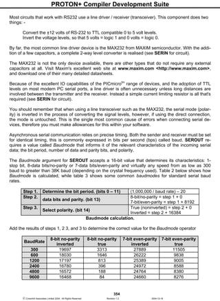
![PROTON+ Compiler Development Suite
356
Crownhill Associates Limited 2004 - All Rights Reserved Revision 1.2 2004-10-18
SEROUT Modifiers.
The example below will transmit a single byte through bit-0 of PORTA at 2400 baud, 8N1, inverted: -
SEROUT PORTA.0 , 16780 , [ 65 ]
In the above example, SEROUT will transmit a byte equal to 65 (the ASCII value of the character "A" )
through PORTA.0. If the PICmicrotm
was connected to a PC running a terminal program such as
HyperTerminal set to the same baud rate, the character "A" would appear on the screen. Always re-
membering that the polarity will differ if a line transceiver such as the MAX232 is used.
What if you wanted the value 65 to appear on the PC's screen? As was stated earlier, it is up to the
receiving side (in serial communication) to interpret the values. In this case, the PC is interpreting the
byte-sized value to be the ASCII code for the character "A". Unless you're also writing the software for
the PC, you cannot change how the PC interprets the incoming serial data, therefore to solve this
problem, the data needs to be translated before it is sent.
The SEROUT command provides a modifier which will translate the value 65 into two ASCII codes for
the characters "6" and "5" and then transmit them: -
SEROUT PORTA.0 , 16780 , [ @ 65 ]
or
SEROUT PORTA.0 , 16780 , [ DEC 65 ]
Notice that the decimal modifier in the SEROUT command is the character @ or word DEC, both
these modifiers do the same thing, which is to inform SEROUT to convert the number into separate
ASCII characters which represent the value in decimal form. If the value 65 in the code were changed
to 123, the SEROUT command would send three bytes (49, 50 and 51) corresponding to the charac-
ters "1", "2" and "3".
This is exactly the same modifier that is used in the RSOUT and PRINT commands.
As well as the DEC modifier, SEROUT may use HEX, or BIN modifiers, again, these are the same as
used in the RSOUT and PRINT commands. Therefore, please refer to the RSOUT or PRINT com-
mand descriptions for an explanation of these. The SEROUT command sends quoted text exactly as it
appears in the OutputData list:
SEROUT PORTA.0 , 16780 , [ "HELLO WORLD" , 13 ]
SEROUT PORTA.0 , 16780 , [ "Num = " , DEC 100 ]
The above code will display "HELLO WORLD" on one line and "Num = 100" on the next line. Notice
that you can combine data to output in one SEROUT command, separated by commas. In the exam-
ple above, we could have written it as one line of code: -
SEROUT PORTA.0 , 16780 , [ "HELLO WORLD" , 13 , "Num = " , DEC 100 ]](https://image.slidesharecdn.com/protondsuserguide-150604211022-lva1-app6891/85/Proton-ds-userguide-358-320.jpg)
![PROTON+ Compiler Development Suite
357
Crownhill Associates Limited 2004 - All Rights Reserved Revision 1.2 2004-10-18
SEROUT also has some other modifiers. These are listed below: -
Modifier Operation
AT ypos,xpos Position the cursor on a serial LCD
CLS Clear a serial LCD (also creates a 30ms delay)
BIN{1..32} Send binary digits
DEC{1..10} Send decimal digits
HEX{1..8} Send hexadecimal digits
SBIN{1..32} Send signed binary digits
SDEC{1..10} Send signed decimal digits
SHEX{1..8} Send signed hexadecimal digits
IBIN{1..32} Send binary digits with a preceding '%' identifier
IDEC{1..10} Send decimal digits with a preceding '#' identifier
IHEX{1..8} Send hexadecimal digits with a preceding '$' identifier
ISBIN{1..32} Send signed binary digits with a preceding '%' identifier
ISDEC{1..10} Send signed decimal digits with a preceding '#' identifier
ISHEX{1..8} Send signed hexadecimal digits with a preceding '$' identifier
REP cn Send character c repeated n times
If a floating point variable is to be displayed, then the digits after the DEC modifier determine how
many remainder digits are printed. i.e. numbers after the decimal point.
DIM FLT AS FLOAT
FLT = 3.145
SEROUT PORTA.0 , 16780 , [DEC2 FLT] ' Send 2 values after the decimal point
The above program will send 3.14
If the digit after the DEC modifier is omitted, then 3 values will be displayed after the decimal point.
DIM FLT AS FLOAT
FLT = 3.1456
SEROUT PORTA.0 , 16780 , [DEC FLT] ' Send 3 values after the decimal point
The above program will send 3.145
There is no need to use the SDEC modifier for signed floating point values, as the compiler's DEC
modifier will automatically display a minus result: -
DIM FLT AS FLOAT
FLT = -3.1456
SEROUT PORTA.0 , 16780 , [DEC FLT] ' Send 3 values after the decimal point
The above program will send -3.145
HEX or BIN modifiers cannot be used with floating point values or variables.](https://image.slidesharecdn.com/protondsuserguide-150604211022-lva1-app6891/85/Proton-ds-userguide-359-320.jpg)
![PROTON+ Compiler Development Suite
358
Crownhill Associates Limited 2004 - All Rights Reserved Revision 1.2 2004-10-18
Using Strings with SEROUT.
The STR modifier is used for transmitting a string of characters from a byte array variable. A string is a
set of characters that are arranged or accessed in a certain order. The characters "ABC" would be
stored in a string with the "A" first, followed by the "B" then followed by the "C". A byte array is a simi-
lar concept to a string; it contains data that is arranged in a certain order. Each of the elements in an
array is the same size. The string "ABC" would be stored in a byte array containing three bytes (ele-
ments).
Below is an example that transmits five bytes (from a byte array) through bit-0 of PORTA at 9600 bps,
N81/inverted: -
DIM SerString[10] AS BYTE ' Create a 10-byte array.
SerString[0] = "H" ' Load the first 5 bytes of the array
SerString[1] = "E" ' With the word "HELLO"
SerString[2] = "L"
SerString[3] = "L"
SerString[4] = "O"
SEROUT PORTA.0 , 16468 , [ STR SerString5 ] ' Send 5-byte string.
Note that we use the optional n argument of STR. If we didn't specify this, the PICmicrotm
would try to
keep sending characters until all 10 bytes of the array were transmitted, or it found a byte equal to 0 (a
NULL terminator). Since we didn't specify a last byte of 0 in the array, and we do not wish the last five
bytes to be transmitted, we chose to tell it explicitly to only send the first 5 characters.
The above example may also be written as: -
DIM SerString[10] AS BYTE ' Create a 10-byte array.
STR SerString = "HELLO" , 0 ' Load the first 6 bytes of the array
SEROUT PORTA.0 , 16468 , [ STR SerString] ' Send first 5-bytes of string.
In the above example, we specifically added a NULL terminator to the end of the string (a zero).
Therefore, the STR modifier within the SEROUT command will output data until this is reached. An al-
ternative to this would be to create the array exactly the size of the text. In our example, the array
would have been 5 elements in length.
Another form of string is used by the CSTR modifier. Note: Because this uses the CDATA command
to create the individual elements it is only for use with PICs that support self-modifying features, such
as the 16F87X, and 18XXXX range of devices.
Below is an example of using the CSTR modifier. It's function is the same as the above examples,
however, no RAM is used for creating arrays.
SEROUT PORTA.0 , 16468 , [ CSTR SerString]
SerString: CDATA "HELLO" , 0
The CSTR modifier will always be terminated by a NULL (i.e. zero at the end of the text or data). If the
NULL is omitted, then the SEROUT command will continue transmitting characters forever.
The SEROUT command can also be configured to pause between transmitted bytes. This is the pur-
pose of the optional Pace operator. For example (9600 baud N8, inverted): -
SEROUT PORTA.0 , 16468 , 1000 , [ "Send this message Slowly" ]](https://image.slidesharecdn.com/protondsuserguide-150604211022-lva1-app6891/85/Proton-ds-userguide-360-320.jpg)
![PROTON+ Compiler Development Suite
359
Crownhill Associates Limited 2004 - All Rights Reserved Revision 1.2 2004-10-18
Here, the PICmicrotm
transmits the message "Send this message Slowly" with a 1 second delay be-
tween each character.
A good reason to use the Pace feature is to support devices that require more than one stop bit. Nor-
mally, the PICmicrotm
sends data as fast as it can (with a minimum of 1 stop bit between bytes). Since
a stop bit is really just a resting state in the line (no data transmitted), using the Pace option will effec-
tively add multiple stop bits. Since the requirement for 2 or more stop bits (on some devices) is really
just a minimum requirement, the receiving side should receive this data correctly.
SEROUT Flow Control.
When designing an application that requires serial communication between PICs, you need to work
within these limitations: -
When the PICmicrotm
is sending or receiving data, it cannot execute other instructions.
When the PICmicrotm
is executing other instructions, it cannot send or receive data.
The compiler does not offer a serial buffer as there is in PCs. At lower crystal frequencies, and higher
serial rates, the PICmicrotm
cannot receive data via SERIN, process it, and execute another SERIN in
time to catch the next chunk of data, unless there are significant pauses between data transmissions.
These limitations can sometimes be addressed by using flow control; the Fpin option for SEROUT and
SERIN. Through Fpin, SERIN can inform another PICmicrotm
sender when it is ready to receive data
and SEROUT (on the sender) will wait for permission to send. Fpin flow control follows the rules of
other serial handshaking schemes, however most computers other than the PICmicrotm
cannot start
and stop serial transmission on a byte-by-byte basis. That is why this discussion is limited to commu-
nication between PICmicros.
Below is an example using flow control with data through bit-0 of PORTA, and flow control through bit-
1 of PORTA, 9600 baud, N8, noninverted: -
SEROUT PORTA.0PORTA.1 , 84 , [SerData]
When SERIN executes, bit-0 of PORTA (Tpin) is made an output in preparation for sending data, and
bit-1 of PORTA (Fpin) is made an input, to wait for the "go" signal from the receiver. The table below
illustrates the relationship of serial polarity to Fpin states.
Serial Polarity Ready to Receive ("Go") Not Ready to Receive ("Stop")
Inverted Fpin is High (1) Fpin is Low (0)
Non-inverted Fpin is Low (0) Fpin is High (1)
See SERIN for a flow control circuit.
The SEROUT command supports open-drain and open-source output, which makes it possible to
network multiple PICs on a single pair of wires. These ‘open baudmodes' only actively drive the Tpin in
one state (for the other state, they simply disconnect the pin; setting it to an input mode). If two PICs in
a network had their SEROUT lines connected together (while a third device listened on that line) and
the PICs were using always-driven baudmodes, they could simultaneously output two opposite states
(i.e. +5 volts and ground). This would create a short circuit. The heavy current flow would likely dam-
age the I/O pins or the PICs themselves.](https://image.slidesharecdn.com/protondsuserguide-150604211022-lva1-app6891/85/Proton-ds-userguide-361-320.jpg)
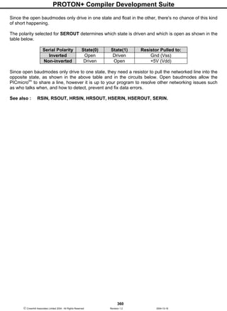
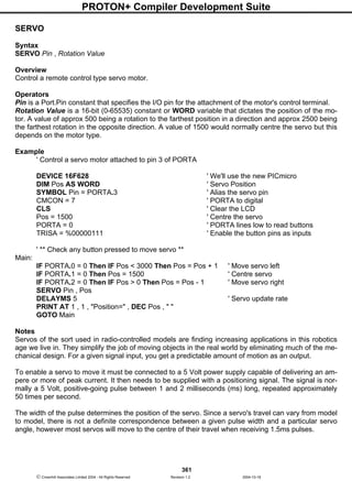
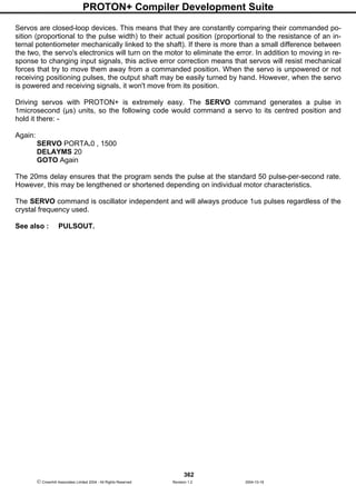
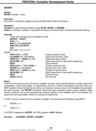
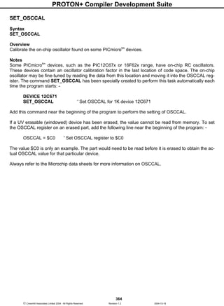
![PROTON+ Compiler Development Suite
366
Crownhill Associates Limited 2004 - All Rights Reserved Revision 1.2 2004-10-18
SHIN
Syntax
SHIN dpin , cpin , mode , [ result { bits } { ,result { bits }...} ]
or
Var = SHIN dpin , cpin , mode , shifts
Overview
Shift data in from a synchronous-serial device.
Operators
Dpin is a Port.Pin constant that specifies the I/O pin that will be connected to the synchronous-serial
device's data output. This pin's I/O direction will be changed to input and will remain in that state after
the instruction is completed.
Cpin is a Port.Pin constant that specifies the I/O pin that will be connected to the synchronous-serial
device's clock input. This pin's I/O direction will be changed to output.
Mode is a constant that tells SHIN the order in which data bits are to be arranged and the relationship
of clock pulses to valid data. Below are the symbols, values, and their meanings: -
Symbol Value Description
MSBPRE
MSBPRE_L
0 Shift data in highest bit first. Read data before
sending clock. Clock idles low
LSBPRE
LSBPRE_L
1 Shift data in lowest bit first. Read data before send-
ing clock. Clock idles low
MSBPOST
MSBPOST_L
2 Shift data in highest bit first. Read data after send-
ing clock. Clock idles low
LSBPOST
LSBPOST_L
3 Shift data in highest bit first. Read data after send-
ing clock. Clock idles low
MSBPRE_H 4 Shift data in highest bit first. Read data before
sending clock. Clock idles high
LSBPRE_H 5 Shift data in lowest bit first. Read data before send-
ing clock. Clock idles high
MSBPOST_H 6 Shift data in highest bit first. Read data after send-
ing clock. Clock idles high
LSBPOST_H 7 Shift data in lowest bit first. Read data after sending
clock. Clock idles high
Result is a bit, byte, or word variable in which incoming data bits will be stored.
Bits is an optional constant specifying how many bits (1-16) are to be input by SHIN. If no bits entry is
given, SHIN defaults to 8 bits.
Shifts informs the SHIN command as to how many bit to shift in to the assignment variable, when
used in the inline format.
Notes
SHIN provides a method of acquiring data from synchronous-serial devices, without resorting to the
hardware SPI modules resident on some PICmicrotm
types. Data bits may be valid after the rising or
falling edge of the clock line. This kind of serial protocol is commonly used by controller peripherals
such as ADCs, DACs, clocks, memory devices, etc.
The SHIN instruction causes the following sequence of events to occur: -](https://image.slidesharecdn.com/protondsuserguide-150604211022-lva1-app6891/85/Proton-ds-userguide-368-320.jpg)
![PROTON+ Compiler Development Suite
367
Crownhill Associates Limited 2004 - All Rights Reserved Revision 1.2 2004-10-18
Makes the clock pin (cpin) output low.
Makes the data pin (dpin) an input.
Copies the state of the data bit into the msb (lsb-modes) or lsb (msb modes) either before (-pre
modes) or after (-post modes) the clock pulse.
Pulses the clock pin high.
Shifts the bits of the result left (msb- modes) or right (lsb-modes).
Repeats the appropriate sequence of getting data bits, pulsing the clock pin, and shifting the result un-
til the specified number of bits is shifted into the variable.
Making SHIN work with a particular device is a matter of matching the mode and number of bits to that
device's protocol. Most manufacturers use a timing diagram to illustrate the relationship of clock and
data.
SYMBOL CLK = PORTB.0
SYMBOL DTA = PORTB.1
SHIN DTA , CLK , MSBPRE , [VAR1] ' Shiftin msb-first, pre-clock.
In the above example, both SHIN instructions are set up for msb-first operation, so the first bit they ac-
quire ends up in the msb (leftmost bit) of the variable.
The post-clock Shift in, acquires its bits after each clock pulse. The initial pulse changes the data line
from 1 to 0, so the post-clock Shiftin returns %01010101.
By default, SHIN acquires eight bits, but you can set it to shift any number of bits from 1 to 16 with an
optional entry following the variable name. In the example above, substitute this for the first SHIN in-
struction: -
SHIN DTA , CLK , MSBPRE , [VAR1 4] 'Shift in 4 bits.
Some devices return more than 16 bits. For example, most 8-bit shift registers can be daisy-chained
together to form any multiple of 8 bits; 16, 24, 32, 40... You can use a single SHIN instruction with mul-
tiple variables.
Each variable can be assigned a particular number of bits with the
backslash () option. Modify the previous example: -
' 5 bits into VAR1; 8 bits into VAR2.
SHIN DTA , CLK , MSBPRE , [ VAR1 5 , VAR2 ]
PRINT "1st variable: " , BIN8 VAR1
PRINT "2nd variable: " , BIN8 VAR2
Inline SHIN Command.
The structure of the INLINE SHIN command is: -
Var = SHIN dpin , cpin , mode , shifts
DPIN, CPIN, and MODE have not changed in any way, however, the INLINE structure has a new op-
erand, namely SHIFTS. This informs the SHIN command as to how many bit to shift in to the assign-
ment variable. For example, to shift in an 8-bit value from a serial device, we would use: -
VAR1 = SHIN DT , CK , MSBPRE , 8
To shift 16-bits into a WORD variable: -
WRD = SHIN DT , CK , MSBPRE , 16](https://image.slidesharecdn.com/protondsuserguide-150604211022-lva1-app6891/85/Proton-ds-userguide-369-320.jpg)
![PROTON+ Compiler Development Suite
368
Crownhill Associates Limited 2004 - All Rights Reserved Revision 1.2 2004-10-18
SHOUT
Syntax
SHOUT Dpin, Cpin, Mode, [OutputData {Bits} {,OutputData {Bits}..} ]
Overview
Shift data out to a synchronous serial device.
Operators
Dpin is a Port.Pin constant that specifies the I/O pin that will be connected to the synchronous serial
device's data input. This pin will be set to output mode.
Cpin is a Port.Pin constant that specifies the I/O pin that will be connected to the synchronous serial
device's clock input. This pin will be set to output mode.
Mode is a constant that tells SHOUT the order in which data bits are to be arranged. Below are the
symbols, values, and their meanings: -
Symbol Value Description
LSBFIRST
LSBFIRST _L
0
Shift data out lowest bit first.
Clock idles low
MSBFIRST
MSBFIRST_L
1
Shift data out highest bit first.
Clock idles low
LSBFIRST _H 4
Shift data out lowest bit first.
Clock idles high
MSBFIRST_H 5
Shift data out highest bit first.
Clock idles high
OutputData is a variable, constant, or expression containing the data to be sent.
Bits is an optional constant specifying how many bits are to be output by SHOUT. If no Bits entry is
given, SHOUT defaults to 8 bits.
Notes
SHIN and SHOUT provide a method of acquiring data from synchronous serial devices. Data bits may
be valid after the rising or falling edge of the clock line. This kind of serial protocol is commonly used
by controller peripherals like ADCs, DACs, clocks, memory devices, etc.
At their heart, synchronous-serial devices are essentially shift-registers; trains of flip flops that receive
data bits in a bucket brigade fashion from a single data input pin. Another bit is input each time the ap-
propriate edge (rising or falling, depending on the device) appears on the clock line.
The SHOUT instruction first causes the clock pin to output low and the data pin to switch to output
mode. Then, SHOUT sets the data pin to the next bit state to be output and generates a clock pulse.
SHOUT continues to generate clock pulses and places the next data bit on the data pin for as many
data bits as are required for transmission.
Making SHOUT work with a particular device is a matter of matching the mode and number of bits to
that device's protocol. Most manufacturers use a timing diagram to illustrate the relationship of clock
and data. One of the most important items to look for is which bit of the data should be transmitted
first; most significant bit (MSB) or least significant bit (LSB).](https://image.slidesharecdn.com/protondsuserguide-150604211022-lva1-app6891/85/Proton-ds-userguide-370-320.jpg)
![PROTON+ Compiler Development Suite
369
Crownhill Associates Limited 2004 - All Rights Reserved Revision 1.2 2004-10-18
Example
SHOUT DTA , CLK , MSBFIRST , [ 250 ]
In the above example, the SHOUT command will write to I/O pin DTA (the Dpin) and will generate a
clock signal on I/O CLK (the Cpin). The SHOUT command will generate eight clock pulses while writ-
ing each bit (of the 8-bit value 250) onto the data pin (Dpin). In this case, it will start with the most sig-
nificant bit first as indicated by the Mode value of MSBFIRST.
By default, SHOUT transmits eight bits, but you can set it to shift any number of bits from 1 to 16 with
the Bits argument. For example: -
SHOUT DTA , CLK , MSBFIRST , [ 250 4 ]
Will only output the lowest 4 bits (%0000 in this case). Some devices require more than 16 bits. To
solve this, you can use a single SHOUT command with multiple values. Each value can be assigned a
particular number of bits with the Bits argument. As in: -
SHOUT DTA , CLK , MSBFIRST , [ 250 4 , 1045 16]
The above code will first shift out four bits of the number 250 (%1111) and then 16 bits of the number
1045 (%0000010000010101). The two values together make up a 20 bit value.
See also : SHIN.](https://image.slidesharecdn.com/protondsuserguide-150604211022-lva1-app6891/85/Proton-ds-userguide-371-320.jpg)
![PROTON+ Compiler Development Suite
372
Crownhill Associates Limited 2004 - All Rights Reserved Revision 1.2 2004-10-18
Another is a change on bit-0 of PORTB. We shall first look at the wake up on change of PORTB,bits-
4..7.
As its name suggests, any change on these pins either high to low or low to high will wake the
PICmicrotm
. However, to setup this mode of operation several bits within registers INTCON and OP-
TION_REG need to be manipulated. One of the first things required is to enable the weak PORTB
pull-up resistors. This is accomplished by clearing the RBPU bit of OPTION_REG (OPTION_REG.7).
If this was not done, then the pins would be floating and random input states would occur waking the
PICmicrotm
up prematurely. Although technically we are enabling a form of interrupt, we are not inter-
ested in actually running an interrupt handler. Therefore, we must make sure that GLOBAL interrupts
are disabled, or the PICmicrotm
will jump to an interrupt handler every time a change occurs on
PORTB. This is done by clearing the GIE bit of INTCON (INTCON.7).
The interrupt we are concerned with is the RB port change type. This is enabled by setting the RBIE
bit of the INTCON register (INTCON.3). All this will do is set a flag whenever a change occurs (and of
course wake up the PICmicrotm
). The flag in question is RBIF, which is bit-0 of the INTCON register.
For now we are not particularly interested in this flag, however, if global interrupts were enabled, this
flag could be examined to see if it was the cause of the interrupt. The RBIF flag is not cleared by
hardware so before entering SLEEP it should be cleared. It must also be cleared before an interrupt
handler is exited.
The SLEEP command itself is then used. Upon a change of PORTB, bits 4..7 the PICmicrotm
will wake
up and perform the next instruction (or command) after the SLEEP command was used. A second ex-
ternal source for waking the PICmicrotm
is a pulse applied to PORTB.0. This interrupt is triggered by
the edge of the pulse, high to low or low to high. The INTEDG bit of OPTION_REG (OPTION_REG.6)
determines what type of pulse will trigger the interrupt. If it is set, then a low to high pulse will trigger it,
and if it is cleared then a high to low pulse will trigger it.
To allow the PORTB.0 interrupt to wake the PICmicrotm
the INTE bit must be set, this is bit-4 of the
INTCON register. This will allow the flag INTF (INTCON.1) to be set when a pulse with the right edge
is sensed. This flag is only of any importance when determining what caused the interrupt. However, it
is not cleared by hardware and should be cleared before the SLEEP command is used (or the interrupt
handler is exited). The program below will wake the PICmicrotm
when a change occurs on PORTB,
bits 4-7.
SYMBOL LED = PORTB.0 ' Assign the LED's pin
SYMBOL RBIF = INTCON.0 ' PORTB[4..7] Change Interrupt Flag
SYMBOL RBIE = INTCON.3 ' PORTB[4..7] Change Interrupt Enable
SYMBOL RBPU = OPTION_REG.7 ' PortB pull-ups
SYMBOL GIE = INTCON.7 ' Global interrupt enable/disable
Main: GIE = 0 ' Turn OFF global interrupts
TRISB.4 = 1 ' Set PORTB.4 as an Input
RBPU = 0 ' Enable PORTB Pull-up Resistors
RBIE = 1 ' Enable PORTB[4..7] interrupt
Again: DELAYMS 100
LOW LED ' Turn off the LED
RBIF = 0 ' Clear the PORTB[4..7] interrupt flag
SLEEP ' Put the PICmicro to sleep
DELAYMS 100 ' When it wakes up, delay for 100ms
HIGH LED ' Then light the LED
GOTO Again ' Do it forever](https://image.slidesharecdn.com/protondsuserguide-150604211022-lva1-app6891/85/Proton-ds-userguide-374-320.jpg)
![PROTON+ Compiler Development Suite
373
Crownhill Associates Limited 2004 - All Rights Reserved Revision 1.2 2004-10-18
SOUND
Syntax
SOUND Pin, [ Note,Duration {,Note,Duration...} ]
Overview
Generates tone and/or white noise on the specified Pin. Pin is automatically made an output.
Operators
Pin is a Port.Pin constant that specifies the output pin on the PICmicrotm
.
Note can be an 8-bit variable or constant. 0 is silence. Notes 1-127 are tones. Notes 128-255 are
white noise. Tones and white noises are in ascending order (i.e. 1 and 128 are the lowest frequencies,
127 and 255 are the highest). Note 1 is approx 78.74Hz and Note 127 is approx 10,000Hz.
Duration can be an 8-bit variable or constant that determines how long the Note is played in approx
10ms increments.
Example
' Star Trek The Next Generation...Theme and ship take-off
DEVICE 16F877
XTAL = 4
DIM LOOP AS BYTE
SYMBOL PIN = PORTB.0
THEME:
SOUND PIN, [50,60,70,20,85,120,83,40,70,20,50,20,70,20,90,120,90,20,98,160]
DELAYMS 500
FOR LOOP = 128 TO 255 ' Ascending white noises
SOUND PIN, [LOOP,2] ' For warp drive sound
NEXT
SOUND PIN, [43,80,63,20,77,20,71,80,51,20,_
90,20,85,140,77,20,80,20,85,20,_
90,20,80,20,85,60,90,60,92,60,87,_
60,96,70,0,10,96,10,0,10,96,10,0,_
10,96,30,0,10,92,30,0,10,87,30,0,_
10,96,40,0,20,63,10,0,10,63,10,0,_
10,63,10,0,10,63,20]
DELAYMS 10000
GOTO THEME
Notes
With the excellent I/O characteristics of the PICmicrotm
, a speaker can be driven through a capacitor
directly from the pin of the PICmicrotm
. The value of the capacitor should be determined based on the
frequencies of interest and the speaker load. Piezo speakers can be driven directly.
See also : FREQOUT, DTMFOUT, SOUND2.](https://image.slidesharecdn.com/protondsuserguide-150604211022-lva1-app6891/85/Proton-ds-userguide-375-320.jpg)
![PROTON+ Compiler Development Suite
374
Crownhill Associates Limited 2004 - All Rights Reserved Revision 1.2 2004-10-18
SOUND2
Syntax
SOUND2 Pin2, Pin2, [ Note1Note2Duration {,Note1,Note2Duration...} ]
Overview
Generate specific notes on each of the two defined pins. With the SOUND2 command more complex
notes can be played by the PICmicrotm
.
Operators
Pin1 and Pin2 are Port.Pin constants that specify the output pins on the PICmicrotm
.
Note is a variable or constant specifying frequency in Hertz (Hz, 0 to 16000) of the tones.
Duration can be a variable or constant that determines how long the Notes are played. In approx 1ms
increments (0 to 65535).
Example 1
' Generate a 2500Hz tone and a 3500Hz tone for 1 second.
' The 2500Hz note is played from the first pin specified (PORTB.0),
' and the 3500Hz note is played from the second pin specified (PORTB.1).
DEVICE = 16F877
XTAL = 20
SYMBOL PIN1 = PORTB.0
SYMBOL PIN2 = PORTB.1
SOUND2 PIN1 , PIN2 , [2500 3500 1000]
STOP
Example 2
' Play two sets of notes 2500Hz and 3500Hz for 1 second
' and the second two notes, 2500Hz and 3500Hz for 2 seconds.
DEVICE = 16F877
XTAL = 20
SYMBOL PIN1 = PORTB.0
SYMBOL PIN2 = PORTB.1
SOUND2 PIN1 , PIN2 , [2500 3500 1000 , 2500 3500 2000 ]
STOP
Notes
SOUND2 generates two pulses at the required frequency one on each pin specified. The SOUND2
command can be used to play tones through a speaker or audio amplifier. SOUND2 can also be used
to play more complicated notes. By generating two frequencies on separate pins, a more defined
sound can be produced. SOUND2 is somewhat dependent on the crystal frequency used for its note
frequency, and duration.
SOUND2 does not require any filtering on the output, and produces a
cleaner note than FREQOUT. However, unlike FREQOUT, the note is
not a SINE wave. See diagram: -
See also : FREQOUT, DTMFOUT, SOUND.
R1
220
R2
220
PIN 1
PIN 2](https://image.slidesharecdn.com/protondsuserguide-150604211022-lva1-app6891/85/Proton-ds-userguide-376-320.jpg)
![PROTON+ Compiler Development Suite
376
Crownhill Associates Limited 2004 - All Rights Reserved Revision 1.2 2004-10-18
STRN
Syntax
STRN Byte Array = Item
Overview
Load a Byte Array with NULL terminated data, which can be likened to creating a pseudo String vari-
able.
Operators
Byte Array is the variable that will be loaded with values.
Item can be another STRN command, a STR command, STR$ command, or a quoted character string
Example
' Load the Byte Array STRING1 with NULL terminated characters
INCLUDE "PROTON_4.INC" ' Demonstration based on the PROTON dev board
DIM STRING1[21] as BYTE ' Create a Byte array with 21 elements
DELAYMS 200 ' Wait for PICmicro to stabilise
CLS ' Clear the LCD
STRN STRING1 = "HELLO WORLD"
' Load STRING1 with characters and NULL terminate it
PRINT STR STRING1 ' Display the string
STOP
See also: Arrays as Strings, STR$.](https://image.slidesharecdn.com/protondsuserguide-150604211022-lva1-app6891/85/Proton-ds-userguide-378-320.jpg)
![PROTON+ Compiler Development Suite
377
Crownhill Associates Limited 2004 - All Rights Reserved Revision 1.2 2004-10-18
STR$
Syntax
STR Byte Array = STR$ (Modifier Variable)
Overview
Convert a DECIMAL, HEX, BINARY, or FLOATING POINT value or variable into a NULL terminated
string held in a byte array. For use only with the STR and STRN commands.
Operators
Modifier is one of the standard modifiers used with PRINT, RSOUT, HSEROUT etc. See list below.
Variable is a variable that holds the value to convert. This may be a BIT, BYTE, WORD, DWORD, or
FLOAT.
Byte Array must be of sufficient size to hold the resulting conversion and a terminating NULL charac-
ter (0).
Notice that there is no comma separating the Modifier from the Variable. This is because the compiler
borrows the format and subroutines used in PRINT. Which is why the modifiers are the same: -
BIN{1..32} Convert to binary digits
DEC{1..10} Convert to decimal digits
HEX{1..8} Convert to hexadecimal digits
SBIN{1..32} Convert to signed binary digits
SDEC{1..10} Convert to signed decimal digits
SHEX{1..8} Convert to signed hexadecimal digits
IBIN{1..32} Convert to binary digits with a preceding '%' identifier
IDEC{1..10} Convert to decimal digits with a preceding '#' identifier
IHEX{1..8} Convert to hexadecimal digits with a preceding '$' identifier
ISBIN{1..32} Convert to signed binary digits with a preceding '%' identifier
ISDEC{1..10} Convert to signed decimal digits with a preceding '#' identifier
ISHEX{1..8} Convert to signed hexadecimal digits with a preceding '$' identifier
Example 1
' Convert a WORD variable to a NULL terminated STRING of characters in a BYTE array.
INCLUDE "PROTON_4.INC" ' Use the PROTON board for the demo
' Create a byte array long enough to hold converted value, and NULL terminator
DIM STRING1[11] AS BYTE
DIM WRD1 AS WORD
DELAYMS 500 ' Wait for PICmicro to stabilise
CLS ' Clear the LCD
WRD1 = 1234 ' Load the variable with a value
STRN STRING1 = STR$(DEC WRD1) ' Convert the Integer to a STRING
PRINT STR STRING1 ' Display the string
STOP
Example 2
' Convert a DWORD variable to a NULL terminated STRING of characters in a BYTE array.
INCLUDE "PROTON_4.INC" ' Use the PROTON board for the demo
' Create a byte array long enough to hold converted value, and NULL terminator
DIM STRING1[11] AS BYTE
DIM DWD1 AS DWORD](https://image.slidesharecdn.com/protondsuserguide-150604211022-lva1-app6891/85/Proton-ds-userguide-379-320.jpg)
![PROTON+ Compiler Development Suite
378
Crownhill Associates Limited 2004 - All Rights Reserved Revision 1.2 2004-10-18
DELAYMS 500 ' Wait for PICmicro to stabilise
CLS ' Clear the LCD
DWD1 = 1234 ' Load the variable with a value
STRN STRING1 = STR$(DEC DWD1) ' Convert the Integer to a STRING
PRINT STR STRING1 ' Display the string
STOP
Example 3
' Convert a FLOAT variable to a NULL terminated STRING of characters in a BYTE array.
INCLUDE "PROTON_4.INC" ' Use the PROTON board for the demo
' Create a byte array long enough to hold converted value, and NULL terminator
DIM STRING1[11] AS BYTE
DIM FLT1 AS FLOAT
DELAYMS 500 ' Wait for PICmicro to stabilise
CLS ' Clear the LCD
FLT1 = 3.14 ' Load the variable with a value
STRN STRING1 = STR$(DEC FLT1 ) ' Convert the Float to a STRING
PRINT STR STRING1 ' Display the string
STOP
Example 4
' Convert a WORD variable to a NULL terminated BINARY STRING
‘ of characters in a BYTE array.
INCLUDE "PROTON_4.INC" ' Use the PROTON board for the demo
' Create a byte array long enough to hold converted value, and NULL terminator
DIM STRING1[34] AS BYTE
DIM WRD1 AS WORD
DELAYMS 500 ' Wait for PICmicro to stabilise
CLS ' Clear the LCD
WRD1 = 1234 ' Load the variable with a value
STRN STRING1 = STR$(BIN WRD1 ) ' Convert the Integer to a STRING
PRINT STR STRING1 ' Display the string
STOP
If we examine the resulting string (Byte Array) converted with example 2, it will contain: -
character 1, character 2, character 3, character 4, 0
The zero is not character zero, but value zero. This is a NULL terminated string.
Notes
The Byte Array created to hold the resulting conversion, must be large enough to accommodate all the
resulting digits, including a possible minus sign and preceding identifying character. %, $, or # if the I
version modifiers are used. The compiler will try and warn you if it thinks the array may not be large
enough, but this is a rough guide, and you as the programmer must decide whether it is correct or not.
If the size is not correct, any adjacent variables will be overwritten, with potentially catastrophic results.
See also : STRN, Arrays as Strings.](https://image.slidesharecdn.com/protondsuserguide-150604211022-lva1-app6891/85/Proton-ds-userguide-380-320.jpg)
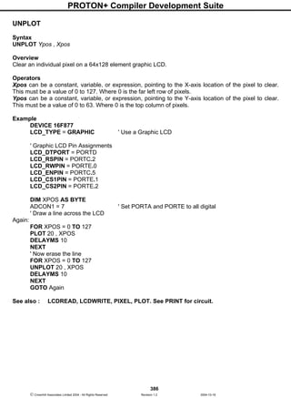
![PROTON+ Compiler Development Suite
387
Crownhill Associates Limited 2004 - All Rights Reserved Revision 1.2 2004-10-18
VAL
Syntax
Variable = VAL (Array Variable , Modifier)
Overview
Convert a Byte Array containing DECIMAL, HEX, or BINARY numeric text into it's integer equivalent.
Operators
Array Variable is a byte array containing the alphanumeric digits to convert and terminated by a NULL
(i.e. value 0).
Modifier can be HEX, DEC, or BIN. To convert a HEX string, use the HEX modifier, for BINARY, use
the BIN modifier, for DECIMAL use the DEC modifier.
Variable is a variable that will contain the converted value. Floating point characters and variables
cannot be converted, and will be rounded down to the nearest integer value.
Example 1
' Convert a string of HEXADECIMAL characters to an integer
INCLUDE "PROTON_4.INC" ' Use the PROTON board for the demo
DIM STRING1[10] AS BYTE ' Create a byte array as a STRING
DIM WRD1 AS WORD ' Create a variable to hold result
DELAYMS 500 ' Wait for PICmicro to stabilise
CLS ' Clear the LCD
STR STRING1 = "12AF",0 ' Load the STRING with HEX digits
WRD1 = VAL(STRING1,HEX) ' Convert the STRING into an integer
PRINT HEX WRD1 ' Display the integer as HEX
STOP
Example 2
' Convert a string of DECIMAL characters to an integer
INCLUDE "PROTON_4.INC" ' Use the PROTON board for the demo
DIM STRING1[10] AS BYTE ' Create a byte array as a STRING
DIM WRD1 AS WORD ' Create a variable to hold result
DELAYMS 500 ' Wait for PICmicro to stabilise
CLS ' Clear the LCD
STR STRING1 = "1234",0 ' Load the STRING with DECIMAL digits
WRD1 = VAL(STRING1,DEC) ' Convert the STRING into an integer
PRINT DEC WRD1 ' Display the integer as DECIMAL
STOP
Example 3
' Convert a string of BINARY characters to an integer
INCLUDE "PROTON_4.INC" ' Use the PROTON board for the demo
DIM STRING1[17] AS BYTE ' Create a byte array as a STRING
DIM WRD1 AS WORD ' Create a variable to hold result
DELAYMS 500 ' Wait for PICmicro to stabilise
CLS ' Clear the LCD
STR STRING1 = "1010101010000000",0 ' Load the STRING with BINARY digits
WRD1 = VAL(STRING1,BIN) ' Convert the STRING into an integer
PRINT BIN WRD1 ' Display the integer as BINARY
STOP](https://image.slidesharecdn.com/protondsuserguide-150604211022-lva1-app6891/85/Proton-ds-userguide-389-320.jpg)
![PROTON+ Compiler Development Suite
388
Crownhill Associates Limited 2004 - All Rights Reserved Revision 1.2 2004-10-18
Notes
There are limitations with the VAL command when used on a 14-bit core device, in that the array must
fit into a single RAM bank. But this is not really a problem, just a little thought when placing the vari-
ables will suffice. The compiler will inform you if the array is not fully located inside a BANK, and there-
fore not suitable for use with the VAL command.
This is not a problem with 16-bit core devices, as they are able to access all their memory very easily.
The VAL command is not recommended inside an expression, as the results are not predictable.
However, the VAL command can be used within an IF-THEN, WHILE-WEND, or REPEAT-UNTIL
construct, but the code produced is not as efficient as using it outside a construct, because the com-
piler must assume a worst case scenario, and use DWORD comparisons.
INCLUDE "PROTON_4.INC" ' Use the PROTON board for the demo
DIM STRING1[10] AS BYTE ' Create a byte array as a STRING
DELAYMS 500 ' Wait for PICmicro to stabilise
CLS ' Clear the LCD
STR STRING1 = "123",0 ' Load the STRING with DEC digits
IF VAL(STRING1,HEX) = 123 THEN ' Compare the result
PRINT AT 1,1,DEC VAL (STRING1,HEX)
ELSE
PRINT AT 1,1,"NOT EQUAL"
ENDIF
STOP
See also: STR, STR$.](https://image.slidesharecdn.com/protondsuserguide-150604211022-lva1-app6891/85/Proton-ds-userguide-390-320.jpg)
![PROTON+ Compiler Development Suite
394
Crownhill Associates Limited 2004 - All Rights Reserved Revision 1.2 2004-10-18
USBIN
Syntax
USBIN Endpoint, Buffer, Countvar, Label
Overview
Receive USB data from the host computer and place it into Buffer.
Operators
Endpoint is a constant value (0 - 2) that indicates which ENDPOINT to receive data from.
Buffer is a BYTE array consisting of no more than 8 elements. The USB adopted by the PICmicrotm
,
only allows 8 pieces of data to be received in a single operation.
Countvar is a constant value (2 - 8) that indicates how many bytes are transferred from the Buffer.
Label must be a valid BASIC label, that USBIN will jump to in the event that no data is available.
Example 1
DIM BUFFER[8] AS BYTE
TRY_AGAIN:
USBIN 1, BUFFER, 4, TRY_AGAIN
Example 2
' Program to demonstrate the USB commands
' Moves the computer's cursor in a small square
DEVICE = 16C765
XTAL = 24
USB_DESCRIPTOR = "MOUSDESC.ASM" ' Point to the DESCRIPTOR file
' Point to the CLASS file (not always required)
USB_CLASS_FILE = "HIDCLASS.ASM"
USB_COUNT_ERRORS = False ' Enable/Disable error monitors
USB_SHOW_ENUM = False ' Enable/Disable PORTB monitor
DIM BUFFER[8] AS BYTE
DIM LOOPCNT AS BYTE
DIM DIRECTION AS Byte
SYMBOL LED = PORTA.5 ' Red LED on PORTA bit 5
' Define the hardware interrupt handler for the USB vector
ON_INTERRUPT GOTO USBINT
'-----------------------------------------------------------------------------------
GOTO START ' Jump over the interrupt handler
'-----------------------------------------------------------------------------------
' Assembly language interrupt handler to check interrupt source and vector to it
USBINT:
MOVLW (Service@USBInt >> 8)
MOVWF PCLATH ' Point PCLATH to the USB subroutines
BTFSC PIR1, USBIF ' Make sure it is a USB interrupt
CALL (Service@USBInt) ' Implement the USB subroutines
CONTEXT RESTORE ' Restore saved registers
'-----------------------------------------------------------------------------------](https://image.slidesharecdn.com/protondsuserguide-150604211022-lva1-app6891/85/Proton-ds-userguide-396-320.jpg)
![PROTON+ Compiler Development Suite
396
Crownhill Associates Limited 2004 - All Rights Reserved Revision 1.2 2004-10-18
USBOUT
Syntax
USBOUT Endpoint, Buffer, Countvar, Label
Overview
Take Countvar number of bytes from the array variable Buffer and send them to the USB Endpoint.
Operators
Endpoint is a constant value (0 - 2) that indicates which ENDPOINT to send data to.
Buffer is a BYTE array consisting of no more than 8 elements. The USB adopted by the PICmicrotm
,
only allows 8 pieces of data to be sent in a single operation.
Countvar is a constant value (2 - 8) that indicates how many bytes are transferred to the Buffer.
Label must be a valid BASIC label, that USBOUT will jump to in the event that the USB buffer does
not have room for the data because of a pending transmission.
Example
DIM BUFFER[8] AS BYTE
TRY_AGAIN:
USBOUT 1, BUFFER, 4, TRY_AGAIN
Notes
The USB subdirectory contains modified Microchip USB libraries. USB programs requires several ad-
ditional files to operate, some of which will require modification for your particular application. See the
text file in the USB subdirectory for more information on the USB commands.
USB communications is a whole lot more complicated than synchronous (SHIN and SHOUT) and
asynchronous (SERIN, SEROUT etc) communications. There is much more to know about USB op-
eration that can possibly be described in this help file, as whole books have been written dealing with
USB.
The USB information on the Microchip web site needs to be studied carefully. Also, the books "USB
Complete", and "USB by example" may be helpful.
See also : USBINIT, USBIN for an example and circuit.](https://image.slidesharecdn.com/protondsuserguide-150604211022-lva1-app6891/85/Proton-ds-userguide-398-320.jpg)
![PROTON+ Compiler Development Suite
397
Crownhill Associates Limited 2004 - All Rights Reserved Revision 1.2 2004-10-18
XIN
Syntax
XIN DataPin , ZeroPin , {Timeout , Timeout Label} , [Variable{,...}]
Overview
Receive X-10 data and store the House Code and Key Code in a variable.
Operators
DataPin is a constant (0 - 15), Port.Bit, or variable, that receives the data from an X-10 interface. This
pin is automatically made an input to receive data, and should be pulled up to 5 Volts with a 4.7KΩ re-
sistor.
ZeroPin is a constant (0 - 15), Port.Bit, or variable, that is used to synchronise to a zero-cross event.
This pin is automatically made an input to received the zero crossing timing, and should also be pulled
up to 5 Volts with a 4.7KΩ resistor.
Timeout is an optional value that allows program continuation if X-10 data is not received within a cer-
tain length of time. Timeout is specified in AC power line half-cycles (approximately 8.33 milliseconds).
Timeout Label is where the program will jump to upon a timeout.
Example
DIM HOUSEKEY AS WORD
CLS
LOOP:
' Receive X-10 data, go to NODATA if none
XIN PORTA.2 , PORTA.0 , 10 , NODATA , [HOUSEKEY]
' Display X-10 data on an LCD
PRINT AT 1 , 1 , "House=" , @HOUSEKEY.BYTE1 , "Key=" , @HOUSEKEY.BYTE0
GOTO LOOP ' Do it forever
NODATA:
PRINT "NO DATA"
STOP
XOUT and XIN Declares
In order to make the XIN command's results more in keeping with the BASIC Stamp interpreter, two
declares have been included for both XIN and XOUT These are.
DECLARE XOUT_TRANSLATE = On/Off, True/False or 1/0
and
DECLARE XIN_TRANSLATE = On/Off, True/False or 1/0
Notes
XIN processes data at each zero crossing of the AC power line as received on ZeroPin. If there are no
transitions on this line, XIN will effectively wait forever.
XIN is used to receive information from X-10 devices that can transmit the appropriate data. X-10
modules are available from a wide variety of sources under several trade names. An interface is re-
quired to connect the PICmicrotm
to the AC power line. The TW-523 for two-way X-10 communications
is required by XIN. This device contains the power line interface and isolates the PICmicrotm
from the
AC line.](https://image.slidesharecdn.com/protondsuserguide-150604211022-lva1-app6891/85/Proton-ds-userguide-399-320.jpg)

![PROTON+ Compiler Development Suite
399
Crownhill Associates Limited 2004 - All Rights Reserved Revision 1.2 2004-10-18
XOUT
Syntax
XOUT DataPin , ZeroPin , [HouseCodeKeyCode {Repeat} { , ...}]
Overview
Transmit a HouseCode followed by a KeyCode in X-10 format.
Operators
DataPin is a constant (0 - 15), Port.Bit, or variable, that transmits the data to an X-10 interface. This
pin is automatically made an output.
ZeroPin is a constant (0 - 15), Port.Bit, or variable, that is used to synchronise to a zero-cross event.
This pin is automatically made an input to received the zero crossing timing, and should also be pulled
up to 5 Volts with a 4.7KΩ resistor.
HouseCode is a number between 0 and 15 that corresponds to the House Code set on the X-10
module A through P. The proper HouseCode must be sent as part of each command.
KeyCode can be either the number of a specific X-10 module, or the function that is to be performed
by a module. In normal use, a command is first sent specifying the X-10 module number, followed by a
command specifying the function required. Some functions operate on all modules at once so the
module number is unnecessary. KeyCode numbers 0-15 correspond to module numbers 1-16.
Repeat is an optional operator, and if it is NOT included, then a repeat of 2 times (the minimum) is as-
sumed. Repeat is normally reserved for use with the X-10 Bright and Dim commands.
Example
DIM HOUSE AS BYTE
DIM UNIT AS BYTE
' Create some aliases of the keycodes
SYMBOL UnitOn = %10010 ' Turn module on
SYMBOL UnitOff = %11010 ' Turn module off
SYMBOL UnitsOff = %11100 ' Turn all modules off
SYMBOL LightsOn = %10100 ' Turn all light modules on
SYMBOL LightsOff = %10000 ' Turn all light modules off
SYMBOL Bright = %10110 ' Brighten light module
SYMBOL DimIt = %11110 ' Dim light module
' Create aliases for the pins used
SYMBOL DATAPIN = PORTA.1
SYMBOL ZERO_C = PORTA.0
HOUSE = 0 ' Set house to 0 (A)
UNIT = 8 ' Set unit to 8 (9)
' Turn on unit 8 in house 0
XOUT DATAPIN ,ZERO_C,[HOUSE UNIT,HOUSE UnitOn ]
XOUT DATAPIN ,ZERO_C,[HOUSE LightsOff ]' Turn off all the lights in house 0
XOUT DATAPIN ,ZERO_C,[HOUSE 0] ' Blink light 0 on and off every 10 seconds
LOOP:
XOUT DATAPIN ,ZERO_C,[HOUSE UnitOn ]
DELAYMS 10000 ' Wait 10 seconds
XOUT DATAPIN ,ZERO_C,[HOUSE UnitOff ]
DELAYMS 10000 ' Wait 10 seconds
GOTO LOOP](https://image.slidesharecdn.com/protondsuserguide-150604211022-lva1-app6891/85/Proton-ds-userguide-401-320.jpg)
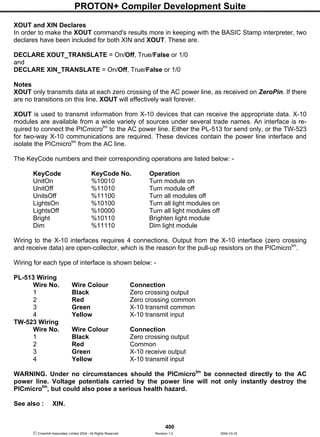


The PROTON IDE provides an integrated development environment for writing, compiling, and programming PIC microcontroller code. It includes features like an advanced code explorer, compiler results window, integrated programmer support, bootloader, and real-time simulation. The IDE aims to accelerate microcontroller development through an easy to use interface.