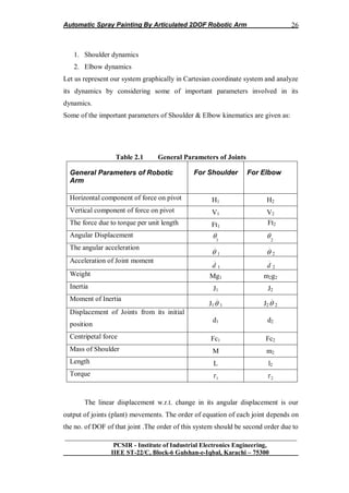
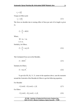
The document provides details about a final project report on an automatic spray painter using a 2-DOF robotic arm. It includes the names and enrollment numbers of the 4 students on the project team. It discusses the external and internal project supervisors. It also includes acknowledgments thanking various people who provided guidance and support. The document is divided into multiple chapters that discuss processes automation, analysis and simulation, implementation proposals, the mechanical structure, and conclusions from the project.


![Automatic Spray Painting By Articulated 2DOF Robotic Arm
__________________________________________________________________
PCSIR - Institute of Industrial Electronics Engineering,
IIEE ST-22/C, Block-6 Gulshan-e-Iqbal, Karachi – 75300
4
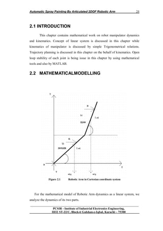
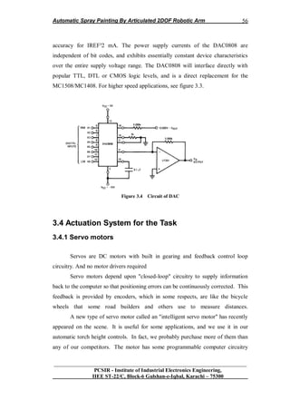
1.1 INTRODUCTION
This chapter deals with detail concept about industrial automation and
robotics. This chapter concern with basic concepts about our task and type of robot
selected for our project and type of joint used in it. Detail Block diagram and
general schematics are also discussed with type of digital controller used. After
going through this chapter readers find them selves well aware about automation
and robotics and about our project.
1.2 Automation and Robotics
Automation is the use of electrical, hydraulic or pneumatic power to move stage
machinery, staging, performers or scenery. The effectiveness of any automation
system depends entirely on the quality of its underlying electrical, mechanical and
control engineering. As computers have changed all aspects of the entertainment
industry so the advances have revolutionized automation making sophisticated
effects ever more widely available. Both in a performance environment and as part
of the supporting infrastructure, the uses and advantages of automation are
manifold. [25]
1.2.1 Advantages of Automation
Absolute control of speed and position Repeatability of moves
1. Coordinating multiple piece moves
2. Offline editing and simulation
3. Moving pieces in complicated paths
4. Reduced manual handling
5. Repeating moves indefinitely
6. Automatic safety checking
7. Improved efficiency
8. Safe movement of a single piece controlled by
9. several motors
10. Movement in confined spaces](https://image.slidesharecdn.com/7573919b-24e9-426a-bbb5-45e558786365-161205174731/85/Project_Report_433-12-320.jpg)
![Automatic Spray Painting By Articulated 2DOF Robotic Arm
__________________________________________________________________
PCSIR - Institute of Industrial Electronics Engineering,
IIEE ST-22/C, Block-6 Gulshan-e-Iqbal, Karachi – 75300
5
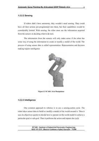
1.2.2 Robotics: Flexible Automation
Most manufacturing automation is called fixed automation. A stamping
machine can stamp only one kind of sheet metal part without being retooled, for
example, or a boring machine bores only one kind of hole in one kind of part.
When robots are part of an automatic process, the process can be changed by
changing the programming of the robots. Robotic automation is called flexible
automation [28].
1.2.2.1 Definition of Robot
Robots are more and more used in industrial and commercial applications.
Now, the number of robots in use is increasing at the rate of about 35% per year.
Sales volume is also increasing at the same rate.
Some of the reasons for the increased use of robots are as follows:
Reduced Production Cost.
Increased Productivity.
Improved Product Quality.
Operation in Hazardous and Hostile Environment.
Improved Management.
Decreased Reaction and Debugging Time
A robot is an autonomous artifact that obtains information by sensing the world
around it and uses the information to manipulate its environment to achieve goals.
Robot sensing includes vision, sound, touch, and others. Manipulation includes the
use of specialized tools and dexterous manipulation. Robots often have the ability
to change their locations in the world (locomotion).](https://image.slidesharecdn.com/7573919b-24e9-426a-bbb5-45e558786365-161205174731/85/Project_Report_433-13-320.jpg)
![Automatic Spray Painting By Articulated 2DOF Robotic Arm
__________________________________________________________________
PCSIR - Institute of Industrial Electronics Engineering,
IIEE ST-22/C, Block-6 Gulshan-e-Iqbal, Karachi – 75300
8
robotic disciplines. Realizing the fullest capabilities of robots will require speech
understanding and common sense reasoning. For a robot to communicate with
people, it will require to have understanding of the world, or at least understanding
of its domain environment. Research projects to achieve this goal have been
underway at universities for many years [28].
1.3 PROJECT DESCRIPTION
Our Project named “Automatic Spray Painter By Articulated 2DOF-
Robotic Arm” is the implementation of theoretical concepts of Modern Control
System. This Project is related with Automation and Robotics (as a Linear System)
theory in Laboratory conditions.
The theme of this Project is to Design 2 Degree of Freedom Robotic Arm
Control in which 2DOF Control will be:
1) Yaw Control of Shoulder.
2) Pitch Control of Elbow.
All of these Controls will be Servo Mechanism based. The Controls of this
system is based on Linear Control system (as some of Robotic Arm Control
System considered as Non-Linear) and is an application of Inverted pendulum. The
End Effecter of this System is Nozzle connected with small compressor (filled with
color) through thin rubber pipe. Flow control of color from Nozzle is through
Servo control Valve. The Work space is Thin Metal Plate of specific Dimensions.
Our goal is to Design Economical, Light Weight, Reliable System which
could be useful for future students to work with this system to achieve more
achievements in Automation & Robotics field.
.](https://image.slidesharecdn.com/7573919b-24e9-426a-bbb5-45e558786365-161205174731/85/Project_Report_433-16-320.jpg)
![Automatic Spray Painting By Articulated 2DOF Robotic Arm
__________________________________________________________________
PCSIR - Institute of Industrial Electronics Engineering,
IIEE ST-22/C, Block-6 Gulshan-e-Iqbal, Karachi – 75300
13
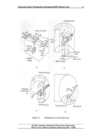
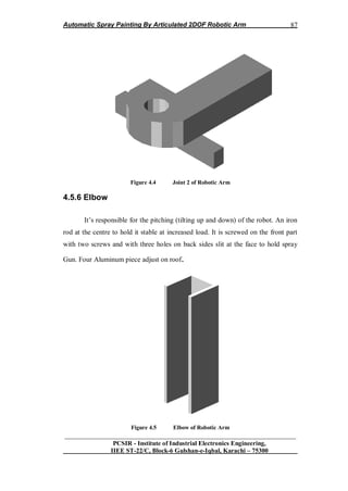
1.3.6 Joint selected for the task
1.3.6.1 Articulated Arm Manipulator
The common industrial manipulator is often referred to as a robot arm, with
links and joints described in similar terms. Manipulators which emulate the
characteristics of a human arm recalled articulated arms. All their joints are rotary
(or revolute). Representative articulated manipulators are the ASEA robot
1.3.6.2 Degree of freedoms
The motion of articulated robot arms differs from the motion of the human
arm. While robot joints have fewer degrees of freedom, they can move through
greater angles. For example, the elbow of an articulated robot can bend up or down
whereas a person can only bend their elbow in one direction with respect to the
straight arm position. Many applications do not require arms with articulated (or
revolute) geometries. Simpler geometries involving prismatic or sliding joints are
often adequate. Prismatic and revolute joints represent the opposite extremes of a
universal screw. In a revolute joint, the screw pitch is zero, constraining the joint to
pure rotation. In a prismatic joint, the pitch is infinite, constraining the joint to pure
sliding motion. Revolute joints are often preferred because of the strength, low
friction and reliability of ball bearings. Joints that allow a combination of
translation and rotation (such as lead screws) are not normally used to join the
links of robot arms [29].
1.3.6.3 Work space consideration
Workspace considerations, particularly reach and collision avoidance, play an
important part in the selection of a robot for an application. All manufacturers give
detailed specifications of the work space of their robots and associated equipment.](https://image.slidesharecdn.com/7573919b-24e9-426a-bbb5-45e558786365-161205174731/85/Project_Report_433-21-320.jpg)
![Automatic Spray Painting By Articulated 2DOF Robotic Arm
__________________________________________________________________
PCSIR - Institute of Industrial Electronics Engineering,
IIEE ST-22/C, Block-6 Gulshan-e-Iqbal, Karachi – 75300
14
1.3.7 SCARA Robot
Consideration of the motions involved in assembly has led to the
development of simpler arm geometry for use in assembly applications, known as
the SCARA (Selective Compliance Automatic Robot Arm) geometry. While all
SCARA robots have the same geometry the name SCARA does not have a
geometric basis. Most assembly operations involve building up the assembly by
placing parts on top of a partially complete assembly. A SCARA arm has two
revolute joints in the horizontal plane, allowing it to reach any point within a
horizontal planar workspace defined by two concentric circles. At the end of the
arm is a vertical link which can translate in the vertical direction, allowing parts to
be raised from a tray and placed on to the assembly. A gripper placed at the end of
this link may be able to rotate about the vertical axis of this link, facilitating
control of part orientation in a horizontal plane. One problem in achieving
spherical wrist design is the physical difficulty of fitting all the components into
the available space. The size of the human wrist is small because the muscles
which power it are located in the forearm, not in the wrist. Wrist design is a
complex task, involving conflicting goals. Desirable features of a wrist include
[29]
Small size
Axes close together to increase mechanical efficiency
Tool plate close to the axes to increase strength and precision
Soluble mathematical model
No singularities in the work volume
Back-driving to allow programming by teach and playback
Decoupling between motions around the three axes
Actuators mounted away from the wrist to allow size reduction
Paths for end effectors control and power through the wrist
Power proportionate to the proposed task
Rugged housing.](https://image.slidesharecdn.com/7573919b-24e9-426a-bbb5-45e558786365-161205174731/85/Project_Report_433-22-320.jpg)
![Automatic Spray Painting By Articulated 2DOF Robotic Arm
__________________________________________________________________
PCSIR - Institute of Industrial Electronics Engineering,
IIEE ST-22/C, Block-6 Gulshan-e-Iqbal, Karachi – 75300
16
1.4.2 Controller
Every robot is connected to a controller (usually a microcontroller), also it
can be connected to a simple home PC, which keeps the pieces of the arm working
together. The controller functions as the "brain" of the robot. Robots today have
controllers that run programs. Usually, entirely pre-programmed by people, robots
have very specific jobs to accomplish.
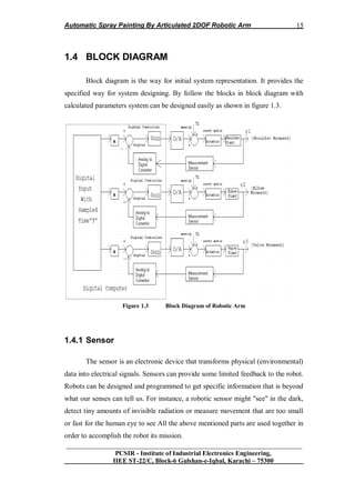
In the block diagram representation of Robotic Arm system there are three
separate servo- Control systems(feedback control loops) due to the fact that
physics involve in system dynamics(motor as an actuator) in Robotic Arm is on the
concept of “Absolute Frame of Reference “. So, three separate Feedback control
loops are drawn having digital input through digital computer with designed
sampled time “T” having switching sequence between loops as desired.
Digital controllers are of “ON-OFF type” for shoulder, elbow and valve
dynamics which are Plants of the system. Feedback sensor is position sensor and is
part of Servo motor by combining called Servomechanism. TL is the Load Torque
on joints due to Actuation Mechanism involving gear & belt system. D/A converter
is to convert discrete signal in to Continuous time signal and A/D converter is to
convert Continuous time signal in to Discrete signal [12].
1.4.3 Robotic Arm
Robotic arms come in all shapes and sizes. The arm is the part of the robot
that sets the end- effectors and sensors to do their preprogrammed job. Many (but
not all) resemble human arms and have shoulders, elbows, and wrists, even fingers.
Each joint gives to the robot one degree of freedom. So, a simple robotic arm with
three degrees of freedom could move in three ways: up and down, left and right,
forward and backward.](https://image.slidesharecdn.com/7573919b-24e9-426a-bbb5-45e558786365-161205174731/85/Project_Report_433-24-320.jpg)
![Automatic Spray Painting By Articulated 2DOF Robotic Arm
__________________________________________________________________
PCSIR - Institute of Industrial Electronics Engineering,
IIEE ST-22/C, Block-6 Gulshan-e-Iqbal, Karachi – 75300
17
1.4.4 Actuation System and Drive
The drive is the engine that drives the links (the sections between the joints)
into their desired position. Very common devices that robots use as drives are
Servomotors and Step-Motors. These two categories are usually connected directly
to a microcontroller. The microcontroller triggers them by generating specific
pulses. They are very useful because they have flexible moving and opposed to the
simple motors they can be set at very specific positions each time. Also, a
characteristic that makes them useful for robots is that they can handle with heavy
items. In other words these kinds of motors can carry heavy parts [15].
1.4.5 End-Effectors
The end-effectors is the "hand" connected to the robots‟ arm. It could be a
tool such as a gripper, tweezers or a scalpel. So, the end-effectors are the part of
the robotic system that characterizes its implementation.
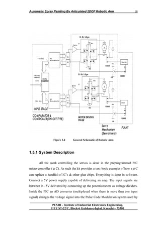
1.5 OVER ALL SYSTEM
Over all system is represented by General Schematics. The General
Schematics of the system have four parts. First part is Comparator and Controller
part which is digital controller (ON-OFF type). Comparison and Controller is done
by using PIC microcontroller. Second part of the system is motor driving stage
consist of H-bridge for bidirectional switching of system. Third stage is servo
mechanism consist of Servo motor with gear system. The last stage is the Plant
which of course Arm Manipulator. General Schematic of system is shown in
figure 1.4.](https://image.slidesharecdn.com/7573919b-24e9-426a-bbb5-45e558786365-161205174731/85/Project_Report_433-25-320.jpg)
![Automatic Spray Painting By Articulated 2DOF Robotic Arm
__________________________________________________________________
PCSIR - Institute of Industrial Electronics Engineering,
IIEE ST-22/C, Block-6 Gulshan-e-Iqbal, Karachi – 75300
19
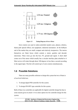
servo motors. This signal is a 5V pulse between 1 and 2 mSec long repeated 50
times per second. That is, a 20msec frame rate.
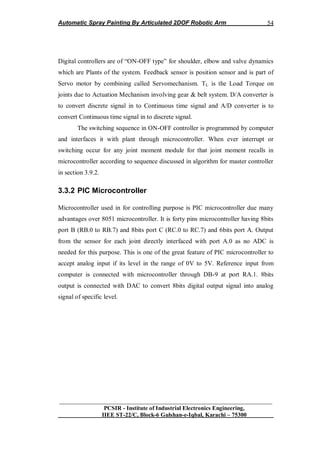
The width of the pulse determines the position of the server. Most servos
will move to the center of their travel when they receive a 1.5msec pulse. One
extreme of motion generally equates to a pulse width of 1.0msec; the other extreme
to 2.0msec with a smooth variation throughout the range, and neutral at 1.5msec.
The period between the pulses is used to synchronize the receiver. Servos are
closed loop devices. They are constantly comparing their position (proportional to
the pulse width) to their actual position (proportional to the signal voltage input.) If
there is a difference between the two the servo electronics will turn the motor to
adjust the difference error. This also means that servos will resist forces which try
to change their position. When a servo is not receiving positioning pulses (i-e not
being provided with power) the output shaft can be easily turned by hand. [18]
1.5.2 Electronics
To guide the servomotors on when and how to move, an electronic board is
needed. On the board (Figure 1), there are some electronic circuits that give to the
preprogrammed microcontroller the ability to communicate with the peripheral
devices (servomotors, sensors, PCs). The board has inputs and outputs that are
connected to the microcontroller. Four outputs are used for the servomotors and
one input for the sensor. One I/O interface based on a DB-9 RS-232 is used for
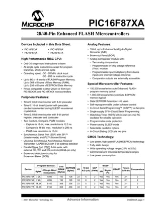
transferring data from and to a PC when connected. The microcontroller is a PIC
model 16F877A (Microchip). PIC has 13 I/O pins, an 8-bit microprocessor and 1K
of RAM. Its circuit is a usual TTL/CMOS based and so its V is +5V. Using the
PWM (Pulse Width Modulation) technique, PIC controls the servomotors. Also
PIC inputs receive signals that come from sensors and may be useable at any case.
In our work we use a supersonic sensor, which transmits high frequencies and then
receives the reflections. In this way PIC can understand where and in which height
a CD is, related to the ground. The board may also communicate with other
external sensors via the PC interface (for sensors connected on the PC) or get](https://image.slidesharecdn.com/7573919b-24e9-426a-bbb5-45e558786365-161205174731/85/Project_Report_433-27-320.jpg)
![Automatic Spray Painting By Articulated 2DOF Robotic Arm
__________________________________________________________________
PCSIR - Institute of Industrial Electronics Engineering,
IIEE ST-22/C, Block-6 Gulshan-e-Iqbal, Karachi – 75300
20
connected with more sensors attached to the board directly via its integrated
sockets (PIC16F877 Tutorial and basic explanations; Microchip PIC16F877A
Technical Specifications 2002; PIC16F877 Fundamentals and Programming
Examples; Programming the PIC16F877 Micro Controller and Data Sheets
Resource Centers Internet Sites).
1.5.3 Assembly
Check the components in the kit against the Components List. Some of the
resistors stand up on the board. Make sure to get the electrolytic capacitor and the
IC1 around the correct way. To complete the kit between 5K - 10K potentiometers
are required to produce the input signal. Connect each pot as a voltage divider with
the center pin going to the signal input. Servo motors are required. They have not
been included in this kit because users will usually have their own particular servos
they wish to control.
1.5.4 Servo Motor
Servo is a small device that has an output shaft. This shaft can be
positioned to specific angular positions by sending the servo a coded signal. As
long as the coded signal exists on the input line, the servo will maintain the angular
position of the shaft. As the coded signal changes, the angular position of the shaft
changes. In practice, servos are used in radio controlled airplanes to position
control surfaces like the elevators and rudders. They are also used in radio
controlled cars, puppets, and of course, robots [20].](https://image.slidesharecdn.com/7573919b-24e9-426a-bbb5-45e558786365-161205174731/85/Project_Report_433-28-320.jpg)
![Automatic Spray Painting By Articulated 2DOF Robotic Arm
__________________________________________________________________
PCSIR - Institute of Industrial Electronics Engineering,
IIEE ST-22/C, Block-6 Gulshan-e-Iqbal, Karachi – 75300
23
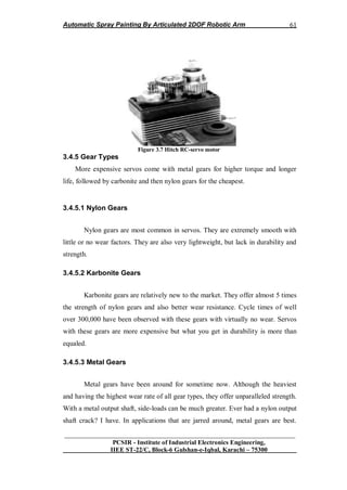
R2 is any small resistance (10-300 ohms). Q1 is a very common type of transistor:
a 2N2222. See part list for a drawing of these, and this for a picture. A transistor
costs no more than 50 cents.
In order to control bi-directional a motor (ON/OFF, and clockwise or
counterclockwise), a H-type circuit is needed. In the second picture, if both upper
left and lower right transistors are ON, the current will flow through the motor
from left to right, yielding a CW rotation.
Trouble is that there is a lost of power. I have not been able to sink more than 500
mA through the motor in the H circuit. It is enough for small motors, but not for
the Lego-type motors who need a full 1 ampere of current.
One alternative is to replace transistors with power-MOSFET. I haven't try,
but you might look at MOSFET H-Bridge Schematic & Theory of Operation for
more. Another alternative that I explored in tutorial 2 is to use a mechanical switch
to control the direction of motion. Relays are electro-magnetic switch that can be
controlled easily with a transistor. Since the current is independent of the
transistor-magnet circuit, there is no lost of power [25].
1.7.2 Communication port
Personal computer needs to communicate to the controller. The two likely
methods are to use the ports available. There is two kind of port. The parallel port
(or printer port) is easy to program, but has a limited capacity at any given time. In
the best case, it can only output 8 bits of information, and can input from sensor 8
bits.
There is a large variety in sensors, ranging from electronic thermometer to
pressure sensors. The simplest kind is the on/off sensors. When pressure is applied,
the switch turns on. One bit of information is enough per sensor.](https://image.slidesharecdn.com/7573919b-24e9-426a-bbb5-45e558786365-161205174731/85/Project_Report_433-31-320.jpg)
![Automatic Spray Painting By Articulated 2DOF Robotic Arm
__________________________________________________________________
PCSIR - Institute of Industrial Electronics Engineering,
IIEE ST-22/C, Block-6 Gulshan-e-Iqbal, Karachi – 75300
24
1.7.3 Sending Command/Receive Data
The first layer is only a list of what can possibly be done with your robot.
Now we need to send specific commands to your robot. Commands can be very
simple, such as "Start motor 3 now", or more complex, such as "Start motor 3, wait
5 seconds, start motor 2, and when sensor 2 gets on, stop all moves." The VBASIC
interface that I proposed in another page is an example which can send only simple
commands. A better interface would accept commands such as "Turn motor 3 for x
seconds" or "Turn motor 3 until sensor 2 gets on".
1.7.4 Constrain Control
Not all moves are safe for the health of your robots. For example, turning
the arm to the left for an indefinite time is risky if your arm cannot do more than
360 degree turns (and most arms can not do that much).
In order to avoid wreckage, your robot should know things about its
limitations. These are called constraints. Example of constraints are:
If the base is turning for more than 5 seconds, then you ought to stop turning the
base.[25].
1.8 Summary
A basic of Robotic Arm is so important for every engineer to step in
Automation and robotics technology. Basic information provided in this chapter is
so helpful for the student of this level to design such type of manipulator on this
level that we proposed in this chapter. Type of block diagram, schematic, type of
controller etc is much helpful to collect idea for their designs.](https://image.slidesharecdn.com/7573919b-24e9-426a-bbb5-45e558786365-161205174731/85/Project_Report_433-32-320.jpg)
![Automatic Spray Painting By Articulated 2DOF Robotic Arm
__________________________________________________________________
PCSIR - Institute of Industrial Electronics Engineering,
IIEE ST-22/C, Block-6 Gulshan-e-Iqbal, Karachi – 75300
27
one DOF of each joint. As this system is one of many applications of Inverted
Pendulum so linear model of this system is established by study the dynamics of
Inverted Pendulum. Many of models of Robotic Arm system is based on nonlinear
system on undergraduate level which is due to lack of awareness of designing on
this level. Following mathematical modeling lead the undergraduate engineers to
aware the proper analyses of dynamics of robotic arm system by consider it as
linear system [27].
To analyze dynamics of arm manipulator, first analyze their Direct
Kinematics & inverse kinematics of joints moment, then analyze the Transfer
Function of whole system.
To analyze the kinematics of arm joints, it is important to analyze kinematics of
shoulder & elbow separately. For this first of all sum the forces perpendicular to
the shoulder & elbow.
Applying condition of equilibrium
For Shoulder joint
1 1 1
J
For Elbow joint
2 2 2
J
Solving the systems along these axis ends up saving lot of algebra.
You should get the following equations [27].
For Shoulder
.. ..
1 1 1 1 1 1 1 1 1sin cos sin cosV H Mg ML M d (2.1)
For Elbow
.. ..
2 2 2 2 2 2 2 2 2 2 2 2 2sin cos sin cosV H m g m l m d (2.2)
Torque () on Shoulder joint](https://image.slidesharecdn.com/7573919b-24e9-426a-bbb5-45e558786365-161205174731/85/Project_Report_433-36-320.jpg)
![Automatic Spray Painting By Articulated 2DOF Robotic Arm
__________________________________________________________________
PCSIR - Institute of Industrial Electronics Engineering,
IIEE ST-22/C, Block-6 Gulshan-e-Iqbal, Karachi – 75300
30
For Elbow
.. ..
2
2 2 2 2 2 2 2 2 2 2( )J m l m gl m l d (2.12)
The direct kinematics of the system is given as:
For shoulder
2 2 2
1 1 1 1( )J ML D MgL ML D d
Therefore time domain analysis of shoulder:
2 2
1 1
2
1
( ) ( )
( )
d t J ML D MgL
t MLD
(2.13)
For Elbow
2 2
2 2 2 2 2 2
2
2 2 2
( ) ( )
( )
d t J m l D m gl
t m l D
(2.14)
The above sets of equations for Elbow and shoulder represent the direct kinematics
of plant.
For inverse kinematics i.e. analyzing angular displacements of plants for given
space coordinate [27].
2.2.1 Actuation Mechanism
The actuation mechanism consists of belt & gear, driven by the DC motor
by which plant works (i.e. shoulder & elbow move).
So overall transfer function depends upon actuation mechanism will depend on
transfer function of DC motor, belt & external gear.](https://image.slidesharecdn.com/7573919b-24e9-426a-bbb5-45e558786365-161205174731/85/Project_Report_433-39-320.jpg)
![Automatic Spray Painting By Articulated 2DOF Robotic Arm
__________________________________________________________________
PCSIR - Institute of Industrial Electronics Engineering,
IIEE ST-22/C, Block-6 Gulshan-e-Iqbal, Karachi – 75300
31
2.2.1.1 Belt & Gear
Load inertial to the motor consists of gear (of radius „r‟) & masses of
shoulder (i.e. m1) & elbow (i.e. m2).
Therefore, Load Torque is given as;
For elbow joint system
1
2
1 1.LT Mr D
Or,
1
2 2
1 1. ( )LT Mr D t
For elbow joint system
2
2 2
2 2 2. ( )LT m r D t
2.2.1.2 Motor
Dynamics of motor will also affect the transfer function of the actuation
mechanism.
Experimentally, the transfer function of armature control servo dc motor is given
as, [27]
.
( )
( ) 1
m
m
Kt
E t D
(2.15)
Or,
( )
( ) ( 1)
m
m
Kt
E t D D
(2.16)
Where,
Km = Steady state gain in rad/s/v
τm = Time constant for motor in sec
Therefore, overall actuation mechanism is given as for shoulder & elbow,](https://image.slidesharecdn.com/7573919b-24e9-426a-bbb5-45e558786365-161205174731/85/Project_Report_433-40-320.jpg)
![Automatic Spray Painting By Articulated 2DOF Robotic Arm
__________________________________________________________________
PCSIR - Institute of Industrial Electronics Engineering,
IIEE ST-22/C, Block-6 Gulshan-e-Iqbal, Karachi – 75300
32
For elbow joint system
2 2
1 1
1
( )
( ) ( 1)
m
m
K Mr Dt
E t D D
2
11
1
( )
( ) ( 1)
m
m
K Mr Dt
E t D
(2.17)
For elbow joint system
Similarly,
2
2 2 2
2
( )
( ) ( 1)
m
m
K m r Dt
E t D
(2.18)
Differential equation of overall system
For shoulder joint system
2 2 2
1 1 1 1
1
2
1 1
( )
( ) 1
m
m
J Ml D Mgl K Mr Dd t
E t Ml D D
2 2 2
1 1 1 1
1
1 1
( )
( ) 1
m
m
K Mr J Ml D Mgld t
E t Ml D D
2 22
1 1 111
2
1 1
( )
( ) 1
m
m
J Ml D MglK rt
E t l D D
(2.19)
For elbow joint system
2 22
2 2 2 2 222
2
2 2
( )
( ) 1
m
m
J m l D m glK rt
E t l D D
(2.20)
By inserting transfer function values from specification table; differential equations
are given as, [27]](https://image.slidesharecdn.com/7573919b-24e9-426a-bbb5-45e558786365-161205174731/85/Project_Report_433-41-320.jpg)
![Automatic Spray Painting By Articulated 2DOF Robotic Arm
__________________________________________________________________
PCSIR - Institute of Industrial Electronics Engineering,
IIEE ST-22/C, Block-6 Gulshan-e-Iqbal, Karachi – 75300
33
For shoulder joint system
2
1
1
( ) 21.4
0.2
( ) 5.52
t D
E t D D
(2.21)
For elbow joint system
2
2
2
( ) 20.7
0.076
( ) 5.52
t D
E t D D
(2.22)
Transfer function for Shoulder joint system,
2
1
2
1
( ) 0.2 4.28
( ) 5.52
s s
E s s s
(2.23)
Transfer function of Elbow joint system,
2
2
2
2
( ) 0.076 1.55
( ) 5.52
s s
E s s s
(2.24)
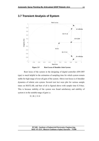
2.3 Stability of Open Loop System
In the light of mathematical model and transfer function in s-domain in
section 2.2. The next step towards designing of system is the analysis of its
stability. There are two ways of analysis. First by mathematical way and second
one is by computer simulation which is actually confirmation of mathematical way
of analysis.[2]
It is clear from the above roots of the system that system is marginary
stable in open loop that one of its pole lie at origin while others are at the left side.
Let the stability of system be analyzed by evaluating d(t) by applying
impulse at input i.e.
e(t) = σ(t)
Where, σ (t) = impulse input
From equation (2.23),
c(t) = 0 .775 – 0.575e-5.52t
(2.25)
Fort , c(∞) = 0.775
Above result clearly shows that system is not unstable in open loop and is
marginary stable for the roots mention above.](https://image.slidesharecdn.com/7573919b-24e9-426a-bbb5-45e558786365-161205174731/85/Project_Report_433-42-320.jpg)
![Automatic Spray Painting By Articulated 2DOF Robotic Arm
__________________________________________________________________
PCSIR - Institute of Industrial Electronics Engineering,
IIEE ST-22/C, Block-6 Gulshan-e-Iqbal, Karachi – 75300
34
It is clear from the above roots of the system that system is marginary
stable in open loop that one of its pole lie at origin while others are at the left
side.[2]
Let the stability of system be analyzed by evaluating d(t) by applying impulse at
input i.e.
e(t) = σ(t)
Where, σ (t) = impulse input
From equation (2.24),
c(t) = 0 .280 – 0.21e-5.52t
(2.26)
Fort , c(∞) = 0.280
Above result clearly shows that system is not unstable in open loop and is
marginary stable for the roots mention above.
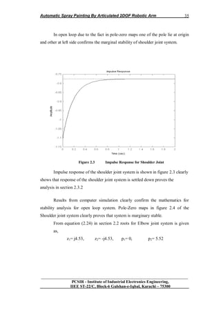
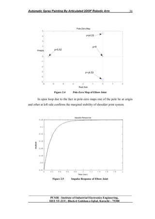
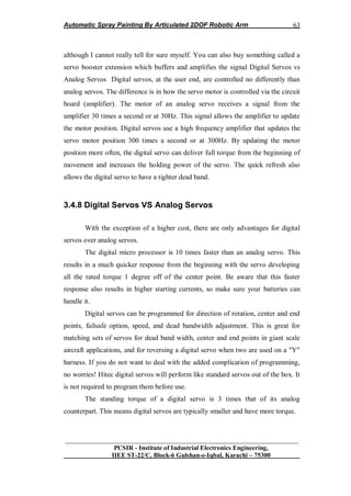
Results from computer simulation clearly confirm the mathematics for
stability analysis for open loop system. Pole-Zero maps in figure 2.2 of the
Shoulder joint system clearly proves that system is marginary stable.
From equation (2.23) in section 2.2 roots for Shoulder joint system is given as,
z1= j4.63, z2= -j4.63, p1= 0, p2= 5.52
Pole-Zero Map
Real Axis
ImaginaryAxis
-6 -5 -4 -3 -2 -1 0 1
-6
-4
-2
0
2
4
6
p=5.52
p=0
z=j4.63
z=-j4.63
Figure 2.2 Pole-Zero Map of Shoulder Joint](https://image.slidesharecdn.com/7573919b-24e9-426a-bbb5-45e558786365-161205174731/85/Project_Report_433-43-320.jpg)
![Automatic Spray Painting By Articulated 2DOF Robotic Arm
__________________________________________________________________
PCSIR - Institute of Industrial Electronics Engineering,
IIEE ST-22/C, Block-6 Gulshan-e-Iqbal, Karachi – 75300
37
Impulse response of the shoulder joint system is shown in figure clearly
shows that response of the shoulder joint system is settled down proves the
analysis in section 2.3.2
2.4 Kinematics of Robotic Arm
Robotic arms are common place in today's world. They are used to weld
automobile bodies, employed to locate merchandise in computerized warehouses,
and used by the Space Shuttle to retrieve satellites from orbit. They are reliable and
accurate. This reliability and accuracy is due to the computer a robot arm uses in
determining where and how it should move. This control computer is programmed
with some basic mathematics. In this paper, we will look at the mathematics
behind robot arms [21].
We will study the two-link robot arm shown in Figure 2.6
Figure 2.6 Two-Link Robotic Arm
Let, θ1 =A and θ2 =B
Most robot arms are more complicated than this, using three links and a
moveable "hand," but with these complications come much more difficult
mathematics. Operation of the two-link arm is simple. The first link (length L1)](https://image.slidesharecdn.com/7573919b-24e9-426a-bbb5-45e558786365-161205174731/85/Project_Report_433-46-320.jpg)
![Automatic Spray Painting By Articulated 2DOF Robotic Arm
__________________________________________________________________
PCSIR - Institute of Industrial Electronics Engineering,
IIEE ST-22/C, Block-6 Gulshan-e-Iqbal, Karachi – 75300
38
pivots around the origin of an XY Cartesian coordinate system while the second
link (length L2) pivots about the connection between the two links. The two pivot
points are drawn as circles. The angle the first link makes with the horizontal (X)
axis is designated A, while the angle the second link makes with the first link is
designated B. The end of the second link is the position of the robot arm, (X, Y).
Arm position (X, Y)? This is simple trigonometry. The second problem is
"inverse kinematics." Here, we want to ask: given the position (X, Y), what angles,
A and B, yield this position? This is a more difficult problem. Lastly, we need to
look at the problem of "trajectory planning." In trajectory planning, we ask: given
our current position (X, Y) and some desired new position, how do we change the
angles A and B to arrive at this new position? We examine each of these problems
separately, using the two-link robot arm [21].
2.4.1 Forward Kinematics
The kinematics problem requires computation of the robot arm Cartesian
position (X, Y), knowing the two link angles, A and B. Referring to Figure 2.6
We can see the position of the end of the first link (X1, Y1) is given by
X1 = L1 cos (A)
Y1 = L1 sin (A)
Then, the end of the second link (X, Y) is simply
X = X1 + L2 cos (A + B)
Y = Y1 + L2 sin (A + B)
Combining these two sets of equations provides the solution to the
kinematics problem:
X = L1 cos (A) + L2 cos (A + B) (2.27)](https://image.slidesharecdn.com/7573919b-24e9-426a-bbb5-45e558786365-161205174731/85/Project_Report_433-47-320.jpg)
![Automatic Spray Painting By Articulated 2DOF Robotic Arm
__________________________________________________________________
PCSIR - Institute of Industrial Electronics Engineering,
IIEE ST-22/C, Block-6 Gulshan-e-Iqbal, Karachi – 75300
39
Y = L1 sin (A) + L2 sin (A + B) (2.28)
An interesting question at this point is: if we cycle A and B through all possible
combinations (-180 degrees < A < 180 degrees, -180 degrees < B < 180 degrees),
what would the region of coverage look like? If L1 and L2 are equal, the region
would be a circle (radius L1 + L2). If L1 and L2 are not equal, the region would be
armular (like a donut). This coverage region becomes important in the inverse
kinematics problem, where we need to know if it's possible to reach a given point
by adjusting the link angles.
2.4.2 Inverse Kinematics
The kinematics problem is seen to be fairly easy to solve. The inverse
problem, that of finding A and B, knowing (X, Y) is not nearly as simple. Let's see
why. [21]
Figure 2.7 Inverse Kinematics
Using the kinematics equations, if we know X and Y, we need to solve the
following for A and B:](https://image.slidesharecdn.com/7573919b-24e9-426a-bbb5-45e558786365-161205174731/85/Project_Report_433-48-320.jpg)
![Automatic Spray Painting By Articulated 2DOF Robotic Arm
__________________________________________________________________
PCSIR - Institute of Industrial Electronics Engineering,
IIEE ST-22/C, Block-6 Gulshan-e-Iqbal, Karachi – 75300
40
L1 cos A) + L2 cos (A + B) = X (2.29)
L1 sin (A) + L2 sin (A + B) = Y (2.30)
This is a nonlinear problem. There are two possible solution approaches:
algebraic and geometric. The algebraic approach (solving the equations directly) is
tedious and involved. For the two-link robot arm, the geometric approach is more
straightforward. We will outline the steps of the algebraic approach to illustrate
some salient points of the inverse kinematics problem. Also, by outlining these
steps, we allow the more industrious reader to see if he/she can solve the problem
algebraically. After this outline, we will develop the solution to the problem with a
geometric approach.
2.4.3 Algebraic Solution
In the algebraic solution, we first square both of the above equations and
add them together. Then, we apply these trigonometric identities: [21]
Cos (A + B) = cos (A) cos (B) – sin (A) sin (B)
Sin (A + B) = cos (A) sin (B) + sin (A) cos (B)
sin2
(C) + cos2
(C) = 1
Where C is any angle
Following these steps, we are able to obtain a relation for cos (B) simply in
terms of X, Y, L1, and L2. That relation is (see if you can find it)
Cos (B) = (X2
+ Y2
– L1
2
- L2
2
)/2L1L2 (2.31)
With this, we can find B by applying the inverse cosine, or can we? What if
cos (B) is greater than one or less than minus one? In these cases, there is no
solution! When this happens, the desired point (X, Y) is not within the coverage
region of the robot arm (as discussed in the previous section). If (X, Y) is in the](https://image.slidesharecdn.com/7573919b-24e9-426a-bbb5-45e558786365-161205174731/85/Project_Report_433-49-320.jpg)
![Automatic Spray Painting By Articulated 2DOF Robotic Arm
__________________________________________________________________
PCSIR - Institute of Industrial Electronics Engineering,
IIEE ST-22/C, Block-6 Gulshan-e-Iqbal, Karachi – 75300
41
coverage region, can we find a unique B? No, just knowing the cosine is not
sufficient. If B is a solution to the above equation, so is -B since
Cos (B) = cos (-B)
Hence, the inverse kinematics problem always has two solutions. This is
shown in Figure 2.7. In "robotics talk," one solution is referred to as "elbow-out"
and one is "elbow-in." To specify which solution we want, we must also find the
sine of B.
Knowing the cosine of B, the sine is given by
Sin (B) = + [1 - cos2
(B)] ½
(2.32)
The angle B is then completely specified by selecting either a plus or minus
sign in this expression. The robot designer must decide which sign to choose based
on problem geometry and current arm configuration. This choice is discussed in
detail in the "Trajectory Planning" section. Figure 2.8 shows the Cartesian
quadrant in which an angle belongs, based on the sign of the two trigonometric
functions.
Figure 2.8 Quadrant System](https://image.slidesharecdn.com/7573919b-24e9-426a-bbb5-45e558786365-161205174731/85/Project_Report_433-50-320.jpg)
![Automatic Spray Painting By Articulated 2DOF Robotic Arm
__________________________________________________________________
PCSIR - Institute of Industrial Electronics Engineering,
IIEE ST-22/C, Block-6 Gulshan-e-Iqbal, Karachi – 75300
42
At this point in the algebraic solution process, we have the angle B. How
do we find A? Knowing B, and hence sin (B) and cos (B), we substitute this (along
with X and Y) back into the kinematics equations. Using the relations for the sine
and cosine of the sum of two angles, the resulting equations will be (again, see if
you can get these)
[L1 + L2 cos (B)] cos (A) – L2 sin (B) sin (A) = X (2.33)
L2 sin (B) cos (A) + [L1 + L2 cos (B)] sin (A) = Y (2.34)
Here, we have two linear equations with two unknowns: sin (A) and cos (A).
Solving these equations (use Cramer's rule) and applying the angle
convention in Figure 2.8 will yield a unique value for A. At this point, we have
solved the inverse kinematics problem with an algebraic approach.
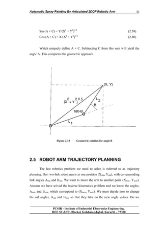
2.4.4 Geometric Solution
The geometric solution is more direct. We can develop expressions for the
angles A and B by simply looking at the geometry of the problem. First, we'll find
B. Figure 4 sketches the configuration necessary for this evaluation. If we look at
the triangle formed by the two links and the line [of length (X2
+ Y2
)1/2
] connecting
the origin to the point (X, Y), we can use the law of cosines to write [21]
X2
+ Y2
= L1
2
+ L2
2
- 2L1 L2 cos (180º - B) (2.35)
But, cos (180º - B) = -cos (B). Substituting this into the equation and
solving for cos (B) yields
Cos (B) = (X2
+ Y2
- L1
2
- L2
2
)/2L1L2 (2.36)](https://image.slidesharecdn.com/7573919b-24e9-426a-bbb5-45e558786365-161205174731/85/Project_Report_433-51-320.jpg)
![Automatic Spray Painting By Articulated 2DOF Robotic Arm
__________________________________________________________________
PCSIR - Institute of Industrial Electronics Engineering,
IIEE ST-22/C, Block-6 Gulshan-e-Iqbal, Karachi – 75300
43
This is exactly the result obtained using the algebraic approach. The
geometric approach is seen to be much simpler. Recall, though, that this does
define a unique angle B. This definition is made by establishing a value for sin (B),
as outlined in the algebraic approach.
The other angle, A, is found with a two step procedure. If we define the
angle between link 1 and the line [length (X2
+ Y2
)1/2
] from (0, 0) to (X, Y) as C
(see Figure 2.9).
Figure 2.9 Geometric solutions for angle A
We can write
Sin (C) = L2 sin (B)/(X2
+ Y2
)1/2
(2.37)
Cos (C) = [L1 + L2 cos (B)]/(X2
+ Y2
)1/2
(2.38)
These expressions define a unique C. Now, using the right triangle (Figure
2.9) defined by the three coordinates (0, 0), (X, 0), and (X, Y), we have](https://image.slidesharecdn.com/7573919b-24e9-426a-bbb5-45e558786365-161205174731/85/Project_Report_433-52-320.jpg)
![Automatic Spray Painting By Articulated 2DOF Robotic Arm
__________________________________________________________________
PCSIR - Institute of Industrial Electronics Engineering,
IIEE ST-22/C, Block-6 Gulshan-e-Iqbal, Karachi – 75300
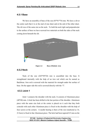
45
change A first, B first, or both simultaneously? In which direction do we change
them? Clockwise? Counterclockwise? This is not a difficult problem if there are no
obstacles in the path of the robot arm, i.e. we have complete freedom of
movement. In that case, we usually move A and B in the direction of smaller
change. That way, we minimize the energy required to move the arm and the time
required to change configuration. [21]
As an example, look at Figure 2.11(a).
Figure 2.11(a): Graph-I
Here, L1 = L2 = 3, Aold = -45 degrees, and Bold = 90 degrees, which
corresponds to a Cartesian location of (Xold, Yold) = (4.24, 0). Check the math using
the kinematics equations. Say we want to move to (Xnew, Ynew) = (-4, 4). To reach
this point, the inverse kinematics equations yield Anew = 115 degrees, Bnew = 39
degrees (see if you can get the same values - I have rounded to the nearest degree).
We'll assume we can only change the angles one at a time. So, to go from (4.24, 0)
to (-4, 4) with minimum angle change, we swing A from -45 to 115 degrees
(counterclockwise) and then B from 90 degrees to 39 degrees (clockwise), as
shown in Figure 2 11(a). What if there was a solid wall in the quadrant where X >
0 and Y > O? In that case, the trajectory in Figure 2.6(a) would not be possible?](https://image.slidesharecdn.com/7573919b-24e9-426a-bbb5-45e558786365-161205174731/85/Project_Report_433-54-320.jpg)
![Automatic Spray Painting By Articulated 2DOF Robotic Arm
__________________________________________________________________
PCSIR - Institute of Industrial Electronics Engineering,
IIEE ST-22/C, Block-6 Gulshan-e-Iqbal, Karachi – 75300
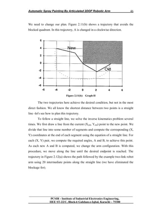
47
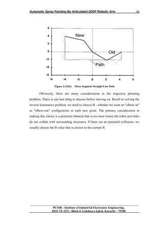
Figure 2.12(a): Path Followed By Two-Link Robot
The path is not a straight line due to the nonlinearities of the robot arm and
the motions as the angles are changed sequentially. If we changed the angles
simultaneously, the path followed would be much smoother. We can extend this
procedure to follow any desired trajectory. This allows us to get around any
obstacles that might be in the way of the arm. Simply draw the desired path and
compute Cartesian points along the path, along with the corresponding joint angles.
Then, cycle through each pair of A and B values until the endpoint is reached.
Figure 2.12(b) shows the arm following a three-segment straight line path from
(4.24, 0) to (-4, 4). Again, this path would be smoother if the angles changed
simultaneously. [21]](https://image.slidesharecdn.com/7573919b-24e9-426a-bbb5-45e558786365-161205174731/85/Project_Report_433-56-320.jpg)

![Automatic Spray Painting By Articulated 2DOF Robotic Arm
__________________________________________________________________
PCSIR - Institute of Industrial Electronics Engineering,
IIEE ST-22/C, Block-6 Gulshan-e-Iqbal, Karachi – 75300
50
3.1 INTRODUCTION
This chapter contain practical design implementation of digital controller
for each joint and concept of difference equation. Transient response is also
discussed in detail by using MATLAB. Hardware design is also presented in this
chapter contain specification table and three dimensional views of different part of
designed manipulator. Software section is also discussed contain algorithms and
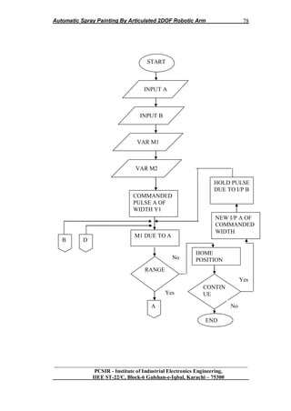
Flowcharts for each joint controller and also for master controller.
Robotic Arm System is represented by blocks in figure 3.1 consists of four
parts named Sensory System, controller and Electronics, Actuation System and
Manipulator Joints as plant.
Figure 1.1 Manipulation Systems
3.2 Sensory System of Robotic Arm
Sensors are the sensory system of a robot much like the five senses that
humans have: touch, sight, sound, smell and taste and measure environmental data
like touch, distance, light, sound, strain, rotation, magnetism, smell, temperature,
inclination, pressure, or altitude. Sensors provide the raw data that must be
processed to provide information to allow the robot to appropriately respond to its
environment. Robots are equipped with sensors so they can have an understanding
of their surrounding environment and make changes in their behavior based on the
information they have gathered. [24]
Sensors allow robots to detect objects and variations in the environment. A
robot will invariably be equipped with a number of sensors which may include: an
acoustic sensor to detect sound, motion or location, infrared sensors to detect heat
Sensory
System
Controller
&
Electronics
Electro-
Mechanical
Actuator
Plant
Manipulator
Joints](https://image.slidesharecdn.com/7573919b-24e9-426a-bbb5-45e558786365-161205174731/85/Project_Report_433-60-320.jpg)
![Automatic Spray Painting By Articulated 2DOF Robotic Arm
__________________________________________________________________
PCSIR - Institute of Industrial Electronics Engineering,
IIEE ST-22/C, Block-6 Gulshan-e-Iqbal, Karachi – 75300
51
sources, contact sensors, tactile sensors to give a sense of touch, or optical/vision
sensors. A robot can also monitor itself with sensors.
3.2.1 Common Sensors for Manipulators
3.2.1.1 Touch Sensors
Touch sensors are basically variable switching devices that work through
pressure.
3.2.1.2 Global Positioning Systems
Global Positioning Systems (GPS) receive signals from orbiting satellites
that pinpoint the location of an outdoor robot on the Earth. [24]
3.2.1.3 Light Sensor
It measures the level of light as a number between 0% (total darkness) and
100% (very bright). Can differentiate light levels reflected from bright and dark
surfaces. Inside the light sensor is a photo-transistor. The photo-transistor acts like
a valve for electricity. The more light energy it senses, the more electricity
flows.[24]
3.2.1.4 Rotation Sensor
It measures the rotation of an axle or shaft. The rotation sensor sends out a
series of voltage pulses. There will be a number of pulses per rotation. In the lego
robotics kits there are 16 of these pulses per one revolution. These pulses are also
referred to as “ticks”, “clicks”, or “counts”.](https://image.slidesharecdn.com/7573919b-24e9-426a-bbb5-45e558786365-161205174731/85/Project_Report_433-61-320.jpg)
![Automatic Spray Painting By Articulated 2DOF Robotic Arm
__________________________________________________________________
PCSIR - Institute of Industrial Electronics Engineering,
IIEE ST-22/C, Block-6 Gulshan-e-Iqbal, Karachi – 75300
52
3.2.2 Sensor Selected for the Task
Rotation sensors (also called encoders) measure the rotation of a shaft or
axle. They are used to measure the angle of a robotic arm, or how far a mobile
robot‟s wheel has turned. [24]
3.2.1.1 Rotation Sensor
It measures the rotation of an axle or shaft. The rotation sensor sends out a
series of voltage pulses. There will be a number of pulses per rotation. In the lego
robotics kits there are 16 of these pulses per one revolution. These pulses are also
referred to as “ticks”, “clicks”, or “counts”.
Figure 2.2 Series of Voltage pulses
3.2.1.2 Pull to Position
In the case of autonomous mobile robots operating in unstructured
environments the position, geometry and orientation of objects of interest are not](https://image.slidesharecdn.com/7573919b-24e9-426a-bbb5-45e558786365-161205174731/85/Project_Report_433-62-320.jpg)
![Automatic Spray Painting By Articulated 2DOF Robotic Arm
__________________________________________________________________
PCSIR - Institute of Industrial Electronics Engineering,
IIEE ST-22/C, Block-6 Gulshan-e-Iqbal, Karachi – 75300
53
known. We aim to use sensor inputs from targets directly to control the motion of
the robot and thereby use the world and its objects as its own best model. The robot
arm structure, dimensions and joint angles, however, are well known and so can be
used for control.
The approach used here is to develop a simple structured linked model of
the articulated limb. The model records link lengths, joint angles and joint
stiffness. The model is manipulated to 'pull' the end of the limb towards the desired
destination position and orientation. The direction of this pulls being derived from
robot sensors. Then the actual motion is realized by driving the joints and linkages
through the trajectories followed by the model. By incorporating continuous
sensory feed-back of joint angles and deriving updated target vectors from target
sensors very simple limb models are sufficient for the control task. Simply 'pulling'
the limb end point [24] towards the destination entails a simple vector mapping
(figure 3.1). Employing servo control of motion direction rather than position
means that the limb will achieve the target point even with simplified modeling.
There is no med to accurately model linkage weights and friction. This control
approach could be considered to be a primitive version of the perception driven
control which living creatures can employ.
3.3 CONTROLLER AND ELECTRONICS
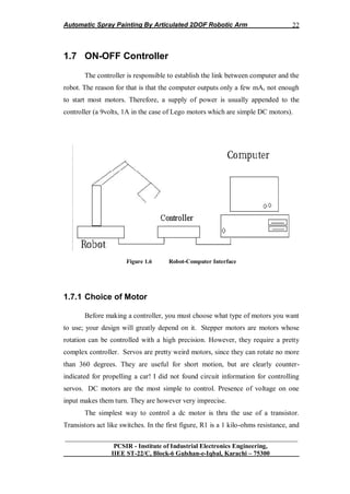
3.3.1 ON-OFF Controller
The controller is responsible to establish the link between computer
and the robot. The reason for that is that the computer outputs only a few mA, not
enough to start most motors. Therefore, a supply of power is usually appended to
the controller (a 9volts, 1A in the case of Lego motors which are simple DC
motors).](https://image.slidesharecdn.com/7573919b-24e9-426a-bbb5-45e558786365-161205174731/85/Project_Report_433-63-320.jpg)
![Automatic Spray Painting By Articulated 2DOF Robotic Arm
__________________________________________________________________
PCSIR - Institute of Industrial Electronics Engineering,
IIEE ST-22/C, Block-6 Gulshan-e-Iqbal, Karachi – 75300
57
incorporated into it, which lets it independently follow simple instructions. It
works well with our torch height controls, due to their low torque demand. We
believe intelligent motors are impractical for driving a cnc machine, for reasons
given below.
The following paragraphs explain each of these types of motors in more
detail.
Figure 3.5 Torque-Speed Curves of Servo Motor
Servo motors are somewhat more expensive than steppers -- perhaps
double the price, or more. They are generally just as accurate, if maintained in a
proper state of tune, however they rely on encoders to provide positioning
information back to the computer. Thus the complexity of the system is at least
doubled, with no accuracy advantage, greater initial cost, and more maintenance
issues. The "closed loop" rhetoric that some manufacturers play up sounds
convincing to the uninitiated, but provides no benefit over a simpler and more
reliable stepper system. [25]
Servo motors are available in larger sizes than stepper motors, and
powerful servos are generally used on heavy machines with gantry carriages in the](https://image.slidesharecdn.com/7573919b-24e9-426a-bbb5-45e558786365-161205174731/85/Project_Report_433-67-320.jpg)
![Automatic Spray Painting By Articulated 2DOF Robotic Arm
__________________________________________________________________
PCSIR - Institute of Industrial Electronics Engineering,
IIEE ST-22/C, Block-6 Gulshan-e-Iqbal, Karachi – 75300
58
500 to 1,000 lb range. They offer no advantage whatsoever on lighter machines,
such as Torch mate and its competitors.
Small intelligent motors with 50 oz. in. peak torque and 28 oz. in.
continuous torque are used on one new competitor's cnc machine, although this is
disguised by the citing of output torque at the gearbox. Although these small
motors are expensive, larger intelligent motors would be far more costly. The only
way these relatively low power motors can drive a gantry on a cnc machine is to
run them at a very high rpm with a large gear reduction. This is kind of like
driving your stick shift car around in low gear. This high rpm greatly increases
motor wear, and introduces planetary gearbox backlash into the equation. When a
gearbox first turns in one direction, and then the other, as in cutting a circle, the
backlash in the gear train must be taken up before the direction changes. Unless
super-expensive low-backlash planetary gear boxes are used, as on the large
$100,000 plus machines, circles don't end up in the same place they started, etc.
[25]
Servos are extremely popular with robot, RC plane, and RC boat builders.
Most servo motors can rotate about 90 to 180 degrees. Some rotate through a full
360 degrees or more. However, servos are unable to continually rotate, meaning
they can't be used for driving wheels (unless modified), but their precision
positioning makes them ideal for robot arms and legs, rack and pinion steering, and
sensor scanners to name a few. Since servos are fully self contained, the velocity
and angle control loops are very easy to implement, while prices remain very
affordable. To use a servo, simply connect the black wire to ground, the red to a
4.8-6V source, and the yellow/white wire to a signal generator (such as from your
microcontroller). Vary the square wave pulse width from 1-2ms and your servo is
now position/velocity controlled](https://image.slidesharecdn.com/7573919b-24e9-426a-bbb5-45e558786365-161205174731/85/Project_Report_433-68-320.jpg)
![Automatic Spray Painting By Articulated 2DOF Robotic Arm
__________________________________________________________________
PCSIR - Institute of Industrial Electronics Engineering,
IIEE ST-22/C, Block-6 Gulshan-e-Iqbal, Karachi – 75300
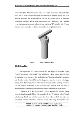
59
3.4.2 Servo Voltage (Red and Black/Brown wires)
Servos can operate under a range of voltages. Typical operation is from 4.8V to
6V. There are a few micro sized servos that can operate at less, and now a few
Hitec servos that operate at much more. The reason for this standard range is
because most microcontrollers and RC receivers operate near this voltage. So what
voltage should you operate at? Well, unless you have a battery
voltage/current/power limitation, you should operate at 6V. This is simply because
DC motors have higher torque at higher voltages
3.4.3 Signal Wire (Yellow/Orange/White wire)
While the black and red wires provide power to the motor, the signal wire
is what you use to command the servo. The general concept is to simply send an
ordinary logic square wave to your servo at a specific wave length, and your servo
goes to a particular angle (or velocity if your servo is modified). The wavelength
directly maps to servo angle so how do you apply this square wave to your servo?
If your robot is remote controlled, your RC receiver will apply the proper square
wave for you. If however your robot is running from a microcontroller, you must:
bring high a digital port wait between 1-2ms bring low the same digital port
cycle a few dozen times per second
Note, if you are running multiple servos simultaneously, you can just put a
few of these program blocks in sequential order. You can run as many servos as
you have of digital ports. [25]
So how many milliseconds do you keep the port high? It all depends on the
servo. You may have to tweak for each individual servo some several
microseconds‟ difference.
The standard time vs. angle is represented in this chart:](https://image.slidesharecdn.com/7573919b-24e9-426a-bbb5-45e558786365-161205174731/85/Project_Report_433-69-320.jpg)
![Automatic Spray Painting By Articulated 2DOF Robotic Arm
__________________________________________________________________
PCSIR - Institute of Industrial Electronics Engineering,
IIEE ST-22/C, Block-6 Gulshan-e-Iqbal, Karachi – 75300
60
Figure 3.6 Timing diagram of servo motor
3.4.4 Servo Current
Servo current operates the same as in a DC motor, except that you now also
have a hard to predict feedback control system to contend with. If your DC motor
is not at the specified angle, it will suddenly draw huge amounts of current to reach
that angle. But there are other peculiarities as well. If you run an experiment with a
servo at a fixed angle and hang precision weights from the servo horn, the
measured current will not be what you expect. One would think that the current
would increase at some fixed rate as the weights increased linearly. Instead you
will get unpredictable curves and multiple rates. In conclusion, servo current draw
is very unpredictable. [25]
3.4.4.1 Stall Torque, Stall Current, Current Drain
Since servos contain DC motors, please read my DC motor tutorial to learn about
servo stall characteristics.](https://image.slidesharecdn.com/7573919b-24e9-426a-bbb5-45e558786365-161205174731/85/Project_Report_433-70-320.jpg)
![Automatic Spray Painting By Articulated 2DOF Robotic Arm
__________________________________________________________________
PCSIR - Institute of Industrial Electronics Engineering,
IIEE ST-22/C, Block-6 Gulshan-e-Iqbal, Karachi – 75300
62
Unfortunately, due to wear, metal gears will eventually develop slight play in the
gear-train. Accuracy will slowly be lost. [25]
3.4.6 Velocity
The servo turn rate, or transit time, is used for determining servo rotational
velocity. This is the amount of time it takes for the servo to move a set amount,
usually 60 degrees. For example, suppose you have a servo with a transit time of
0.17sec/60 degrees at no load. This means it would take nearly half a second to
rotate an entire 180 degrees. More if the servo were under a load. This information
is very important if high servo response speed is a requirement of your robot
application. It is also useful for determining the maximum forward velocity of your
robot if your servo is modified for full rotation. Remember, the worst case turning
time is when the servo is at the minimum rotation angle and is then commanded to
go to maximum rotation angle, all while under load. This can take several seconds
on a very high torque servo.
3.4.7 Efficiency and Noise
Due to noise and control circuitry requirements, servos are less efficient
than DC motors uncontrolled. To begin with, the control circuitry typically drains
5-8mA just on idle. Secondly, noise can more than triple current draw during a
holding position (not moving), and almost double current during rotation. Noise is
often a major source of servo inefficiency and therefore should be avoided. Ever
notice your servo jitter or vibrate? This is because your servo is rapidly jumping
between two different angles due to interference. What causes this interference?
Well the signal wire is no different than long antennae, capable of accepting
unwanted foreign signals and sending them straight to your servo as a command. A
common interference source is usually from other nearby servos and/or servo
wiring. How to prevent this problem? Keep your signal wire short, meaning do not
add say 3+ feet of extension cables to your servo. If you have many servo wires
going through one area, and it isn‟t feasible to keep them apart, then twist them
together. Supposedly this reduces cross interference and I've heard it works,](https://image.slidesharecdn.com/7573919b-24e9-426a-bbb5-45e558786365-161205174731/85/Project_Report_433-72-320.jpg)
![Automatic Spray Painting By Articulated 2DOF Robotic Arm
__________________________________________________________________
PCSIR - Institute of Industrial Electronics Engineering,
IIEE ST-22/C, Block-6 Gulshan-e-Iqbal, Karachi – 75300
64
3.4.9 Hitec vs Futaba
There are actually four major servo manufacturers - Hitec, Futaba,
Airtronics, and JR Radios. The last two are uncommon today, so I wont talk about
them. Hitec and Futaba servos work the same, but there are several interfacing
differences which you should be aware of.
Figure 3.8 (a) Wire Configuration (b) Wire Configuration
The first is wire color, as Hitec uses a yellow signal wire while Futaba uses
a white one. The wiring order is the same, just different colors.
The second is connector compatibility. Futaba (J type) has a special flange thingy
while Hitec (S type, for universal) does not. Futaba has the extra flange to help the
user plug in the servo correctly, although there are only two ways to do it and
connecting a servo in the wrong way will not actually damage anything. If you
want to connect a Futaba servo to a Hitec device, just clip the flange off and use
sandpaper to file it down until it fits. If you ever need to connect a Hitec connector
to something Futaba, just use sandpaper to decrease the connector width until it
fits. [25]
The third is price. All things kept the same; Hitec servos are cheaper than
Futaba servos. But don't let this be your only determining factor in your decision,
as Futaba has some servo sizes that Hitec does not.
The last major difference is in the spline. The spline is the output shaft of
the servo. This is where you would attach your servo horn or servo arm. Standard
Hitec splines have 24 teeth while standard Futaba splines have 25 teeth. What
makes this important is that servo horns built for one will not work with the other.](https://image.slidesharecdn.com/7573919b-24e9-426a-bbb5-45e558786365-161205174731/85/Project_Report_433-74-320.jpg)
![Automatic Spray Painting By Articulated 2DOF Robotic Arm
__________________________________________________________________
PCSIR - Institute of Industrial Electronics Engineering,
IIEE ST-22/C, Block-6 Gulshan-e-Iqbal, Karachi – 75300
65
3.5 ARM MANIPULATOR
Plant of the System is the manipulator joints called Shoulder joint and
Elbow joint. Main feature of these joints are Link joints, material selection,
Specification of different joints parameters and sketches of views of different parts
discussed in below.
3.5.1 Hardware Design
This section reports the mechanical design of actuators and links of the
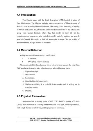
robotic arm. [23]
3.5.2 Planning about Hardware of the System
To considered the Area of Work space.
Length and Span of Shoulder & Elbow w.r.t. Work Space
Maximum Angular Displacement of both joints.
Other Geometrical Parameters.
Mass of shoulder & elbow.
Mathematical modeling & Trajectory Planning.
Selection of Light, Stiff & Easy to Fabricate Material.
Selection of Servomotors of proper power & load bearing capability
3.5.3 Link Design
We use finite-element method to optimize the design of two links of robotic
arm. The objective of optimization was to converge on link design that would
cause the robotic arm to exhibit high structural vibration frequencies over entire
workspace of the robotic arm. The continuously varying nature of structure results
in change in the stiffness and mass characteristic relative to a fixed reference,
necessitating a range of resonant frequencies is predicted. Hence we optimized the
design and evaluated structural vibration modes over a large chunk of the
workspace.](https://image.slidesharecdn.com/7573919b-24e9-426a-bbb5-45e558786365-161205174731/85/Project_Report_433-75-320.jpg)
![Automatic Spray Painting By Articulated 2DOF Robotic Arm
__________________________________________________________________
PCSIR - Institute of Industrial Electronics Engineering,
IIEE ST-22/C, Block-6 Gulshan-e-Iqbal, Karachi – 75300
67
3.6 Designing of Digital Controller
Digital controller used for this task is ON-OFF type as mention in
Article 1.2.3. [2]
There are several steps in Digital control design which are:
Step1: Output parameter D(z) for step input R(z).
)(
)(1
)(
)( zR
zG
zG
zC
[2] (3.1)
Therefore, for Shoulder
)4493.4492.12.1)(1(
2726.02722.02.0(
)( 2
2
2
zzz
zzz
zC (3.2)
Similarly, for Elbow
)279.2827.1076.1)(1(
)1023.01057.0076.0(.
)( 2
2
2
zzz
zzz
zC (3.3)
Step 2: Digital Controller Gc(z)
))(/)(1(
)(/)(
)(
1
)(
zRzC
zRzC
zG
zGc
[2] (3.4)
Therefore, for shoulder
2726.02722.02.0
1767.177.1
)( 2
2
1
zz
zz
zGc (3.5)
Similarly for Elbow
3813.3884.1
1767.0177.1
)( 2
2
2
zz
zz
zGc (3.6)
Step3: Manu plated Output Variable
M(z) = Gc(z) E(z) (3.7)
Difference equation of controller for shoulder
m1(k) = 1.131m(k-1)-0.2m(k-2) +1.25e(k)-1.5e(k-1)+0.221e(k-2) (3.8)
Difference equation of controller for Elbow
m2(k) = 1.3884m(k-1)-0.3818m(k-2)+e(k)-1.177e(k-1)+0.1767e(k-2) (3.9)](https://image.slidesharecdn.com/7573919b-24e9-426a-bbb5-45e558786365-161205174731/85/Project_Report_433-77-320.jpg)


![Automatic Spray Painting By Articulated 2DOF Robotic Arm
__________________________________________________________________
PCSIR - Institute of Industrial Electronics Engineering,
IIEE ST-22/C, Block-6 Gulshan-e-Iqbal, Karachi – 75300
II
DelayMS 4
Next j
SerIn PORTB.7,16468,[info] „Receive Data serially and „save in
“info” variable
‘**********************************************************************
‘* Decide on the base of received data which sub routine to execute *
‘**********************************************************************
If info="A" Then
GoSub sub_A
EndIf
If info="B" Then
GoSub sub_B
EndIf
If info="C" Then
GoSub sub_C
EndIf
If info="D" Then
GoSub sub_D
EndIf
If info="E" Then
GoSub sub_E
EndIf
If info="F" Then
GoSub sub_F
EndIf
If info="G" Then
GoSub sub_G
EndIf
If info="H" Then
GoSub sub_H
EndIf
If info="I" Then
GoSub sub_I
EndIf
If info="J" Then
GoSub sub_J](https://image.slidesharecdn.com/7573919b-24e9-426a-bbb5-45e558786365-161205174731/85/Project_Report_433-110-320.jpg)