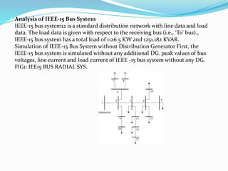
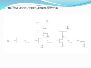
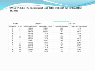
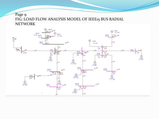
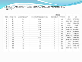
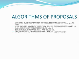
1. OPTIMAL COORINATION OF OVER
CURRENT RELAYS IN MICROGRID
NAME UNIVERSITY ROLL NO
JOY SAMANTA 17601620008
PUJA DAS 17601621019
SOUVIK RANA 17601621036
ANIRBAN CHATTERJEE 17601621027
Under the guidance of
MR. ANIKENDU MAITRA
Assistant Professor of Electrical Engineering
HOOGHLY ENGINEERING
2. CONTENT
CHAPTER1
1 Concept of micro grid
2 Concept of distribution system
Proposed methods: IEEE 15bus
3 System case study Description: E-TAP model of IEEE bus
4 Load flow analysis: Current at each branch
5 Fault analysis: At each branch to transmission lines
3. 2.1CONCEPT OF MICRO GRID:
2.2.1. WHAT IS MICROGRID: A Microgrid is a small-scale power grid that
can
operate independently or in conjunction with a larger power grid. It is an
integrated energy system consistingdistributed energy resources, such as
renewable energy sources, energy storage devices, and backup generators that
are located close to the end-users.
Microgrids can operate in two modes: grid-connected mode and islanded
mode.
4. DISTRIBUTION NETWORK: The electric power distribution network, often
referred to as the power grid or the electrical grid, is a complex system that delivers
electricity from power plantsto consumers. It is an essential part of the
infrastructure in modern society, enabling thetransmission and distribution of
electrical energy over long distances.
TYPES OF DISTRIBUTION NETWORK: There are three types of distribution
network.
These are -
Radial distribution system: The Radial distribution system is the cheapest to
build, is widely used in sparsely populated areas. A radial system has only one
power source for a group of customers. A power failure, short-circuit, or adowned
power line would interrupt power in the entire line which must be fixed before
power can be restored.
Ring or Loop distribution system: Ringdistribution systems are designed so that
every distribution transformer connects with two feeders using different paths.
Thesefeeders form a loop that starts at the substation bus bars, goes through the
load area feeding distribution transformers and returns to the substation bus bars.
Interconnected distribution system: When a ring main feeder is energized by
two or more
substations or generating stations, it is called as an interconnected distribution
system.
5. Dispersed Generation:
Distributed Generation (DG) using many small generators of 2-50 MW
output, installed at various strategic points throughout the area, so that each
provides power to a small number of consumers nearby. These may be solar,
mini/micro hydel or wind turbine units, highly efficient gas turbines,
combined cycle plants, since these are the most economical choices.
Dispersed generation refer to use of still smaller generating units, of less than
500 kW output and often sized to serve
individual homes or businesses. Micro gas turbines, fuel cells, diesel, and
small wind and solar PV generators make up this category.
6. Over current protection of the relay
The Three-Phase Over Current Relay is a protective relay that is sensitive to
overcurrent conditions in three-phase power systems. It trips when the
current in any one of the three phases exceeds the current setpoint. Current
setpoint and time delay adjustments are provided along with two sets of
contacts.
The relay monitors this current and activates protective
Measures if it exceeds a predetermined threshold. This helps prevent
damage to equipment and ensures the system's reliability.
7. Analysis of IEEE-15 Bus System
IEEE-15 bus system12 is a standard distribution network with line data and load
data. The load data is given with respect to the receiving bus (i.e., ‘To’ bus).,
IEEE-15 bus system has a total load of 1126.5 KW and 1251.182 KVAR.
Simulation of IEEE-15 Bus System without Distribution Generator First, the
IEEE-15 bus system is simulated without any additional DG. peak values of bus
voltages, line current and load current of IEEE -15 bus system without any DG.
FIG1: IEE15 BUS RADIAL SYS.
9. DATA TABLE1: The line data and load datas of IEEE15 bus for load flow
analysis
10. Page 9
FIG: LOAD FLOW ANALYSIS MODEL OF IEEE15 BUS RADIAL
NETWORK
11. TABLE : CASE STUDY- LOAD FLOW AND FAULT ANALYSIS ETAP
REPORT
12. ALGORITHMS OF PROPOSALS
LINE DATA: BUS LINE DATA TAKEN FROM IEE15 BUS STANDARD MODEL 1.35309 TO
1.9702
LOAD DATA: BUS LOAD DATA TAKEN FROM IEE15 BUS STANDARD MODEL 70.3 TO 3.6
MAX LOAD CURRENT:AT BUS TERMINAL 1 TO 2, 84.36.
TERMINAL BUS AND BRANCH:BUS 14 AND BRANCH Z8.
UNIQUE BUS:BUS 2 ,ITS CORRESPONDING LINES ARE 4,3,9,10,11,12,13,14,15 .