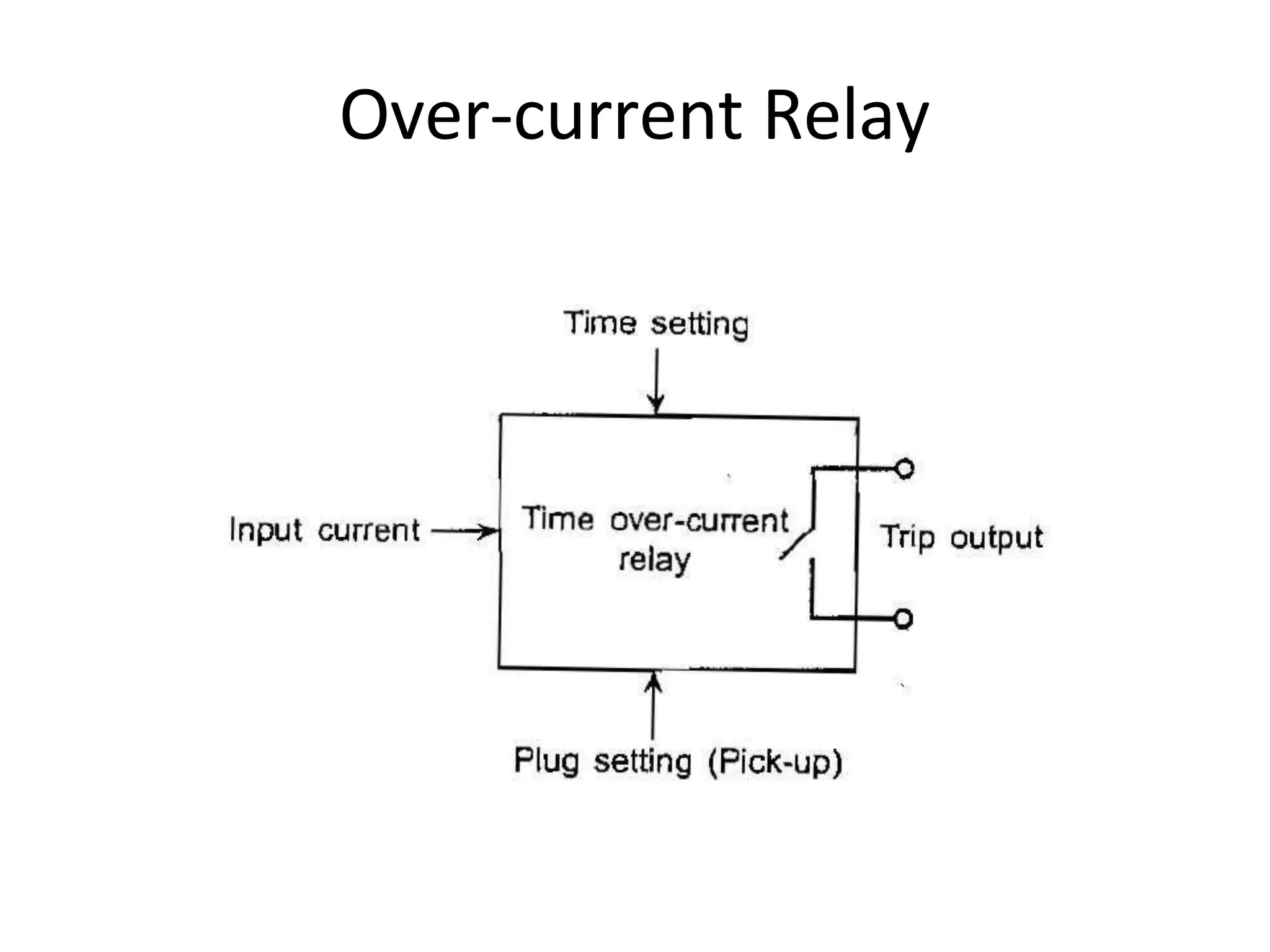
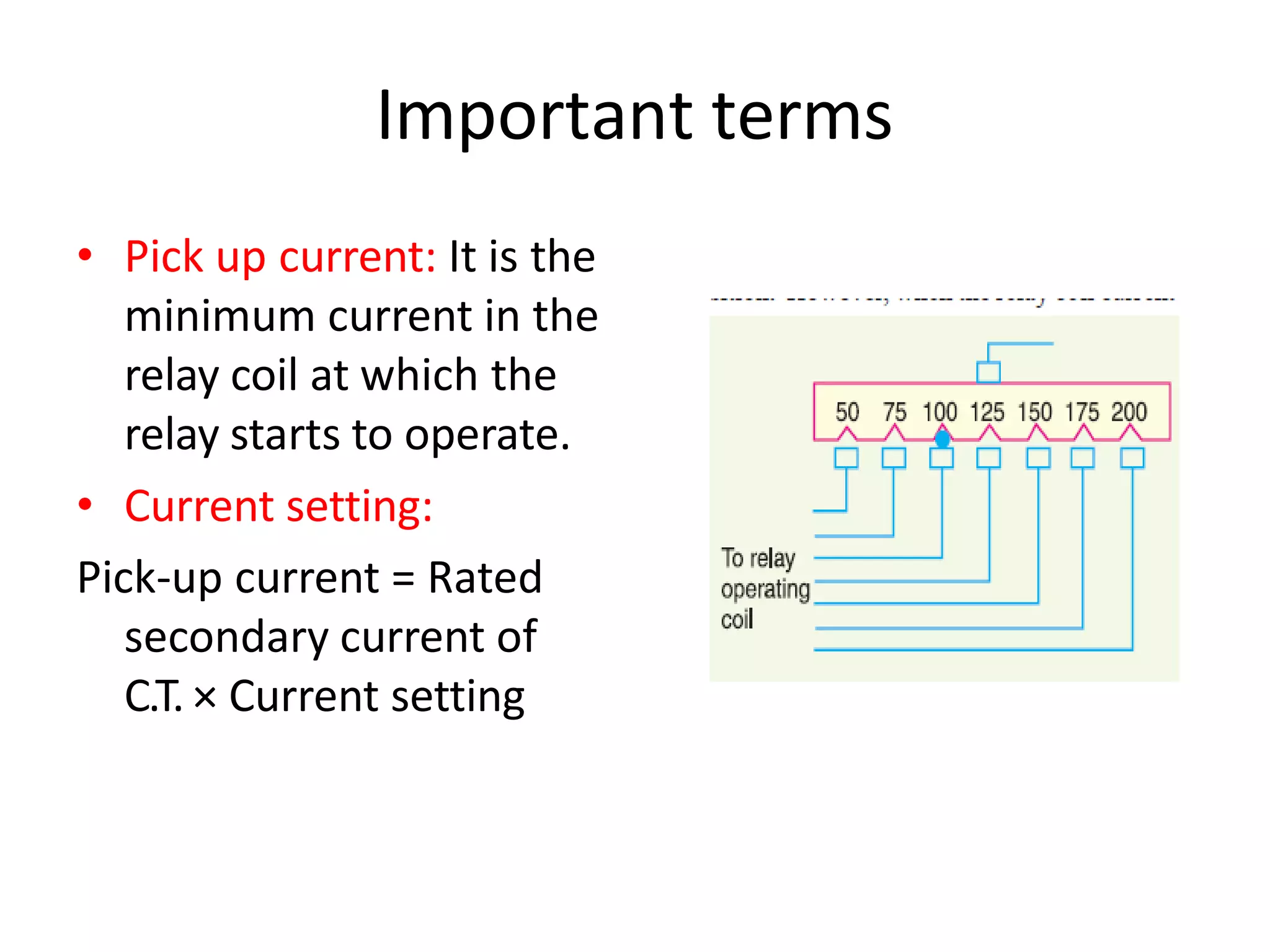
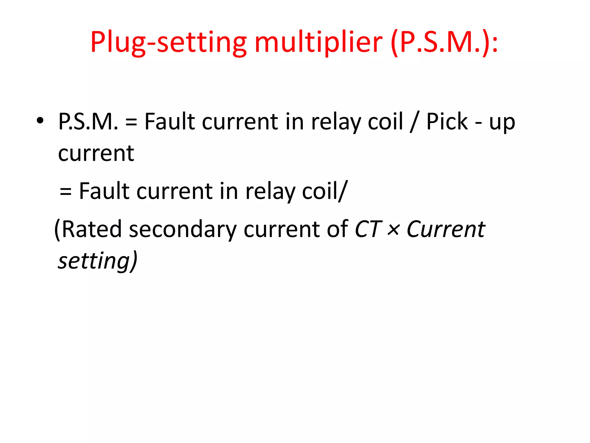
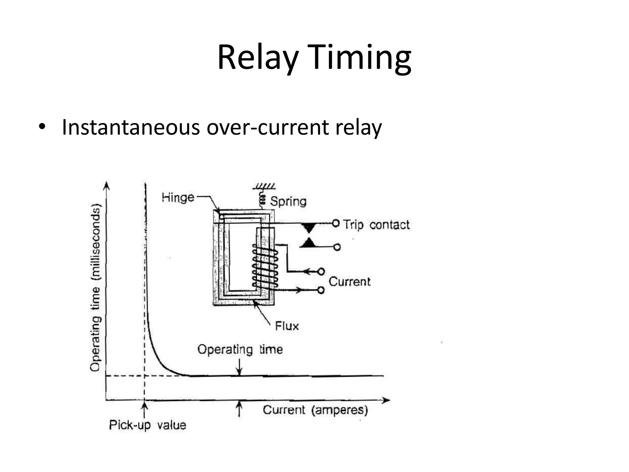
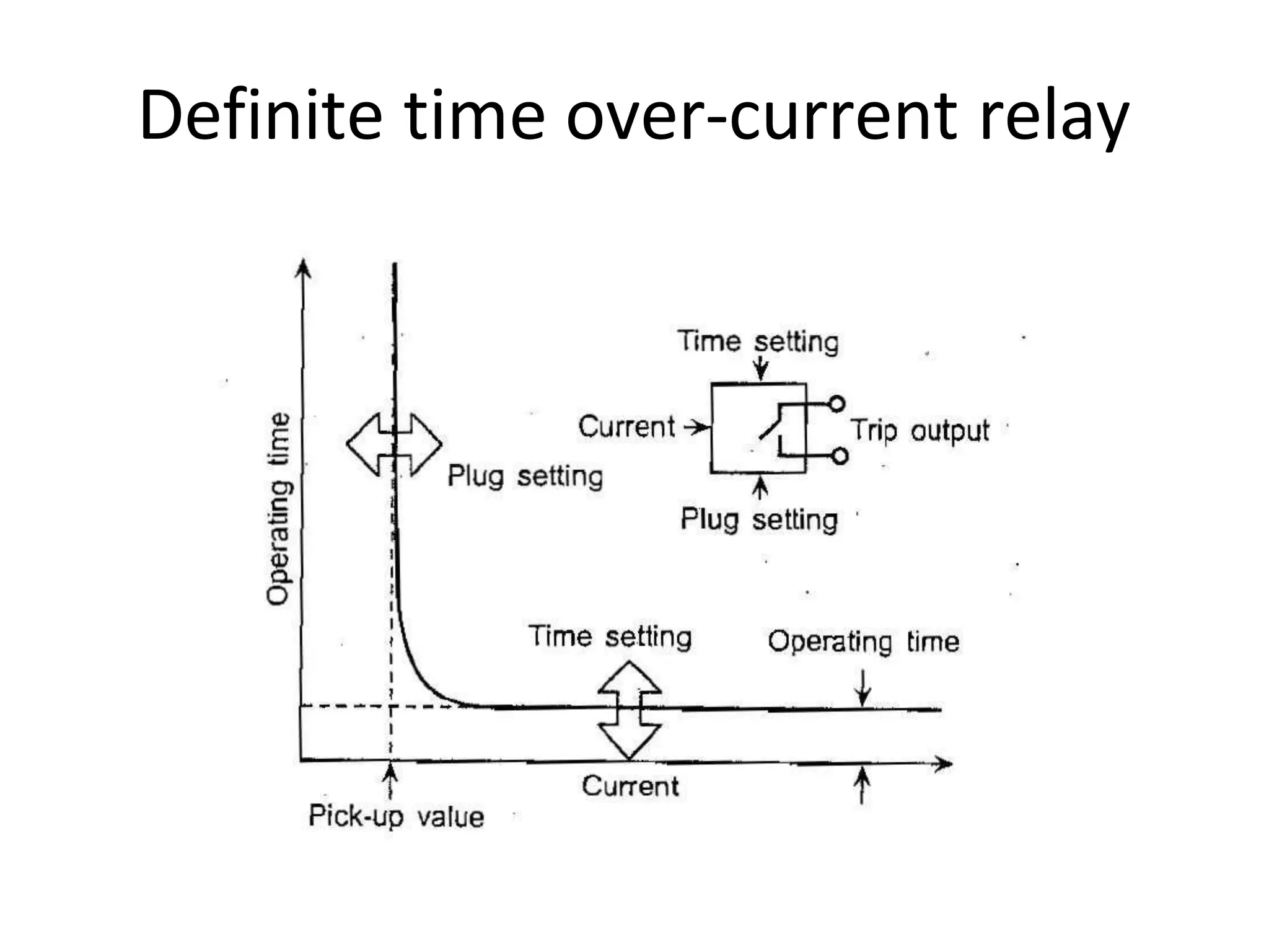
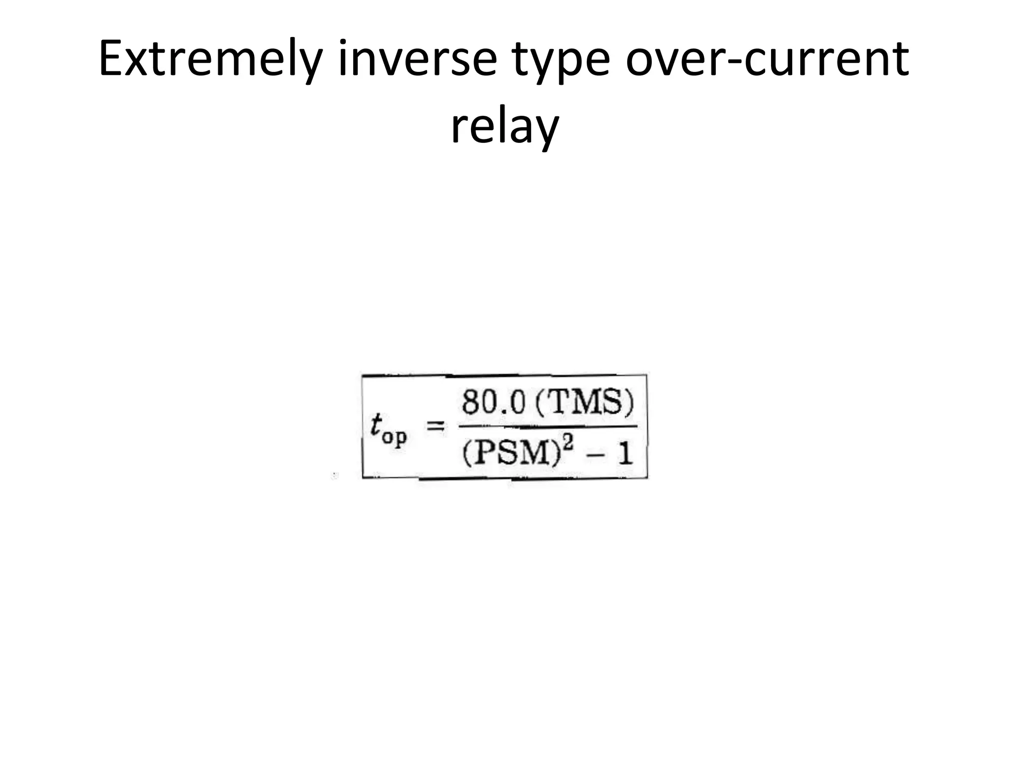
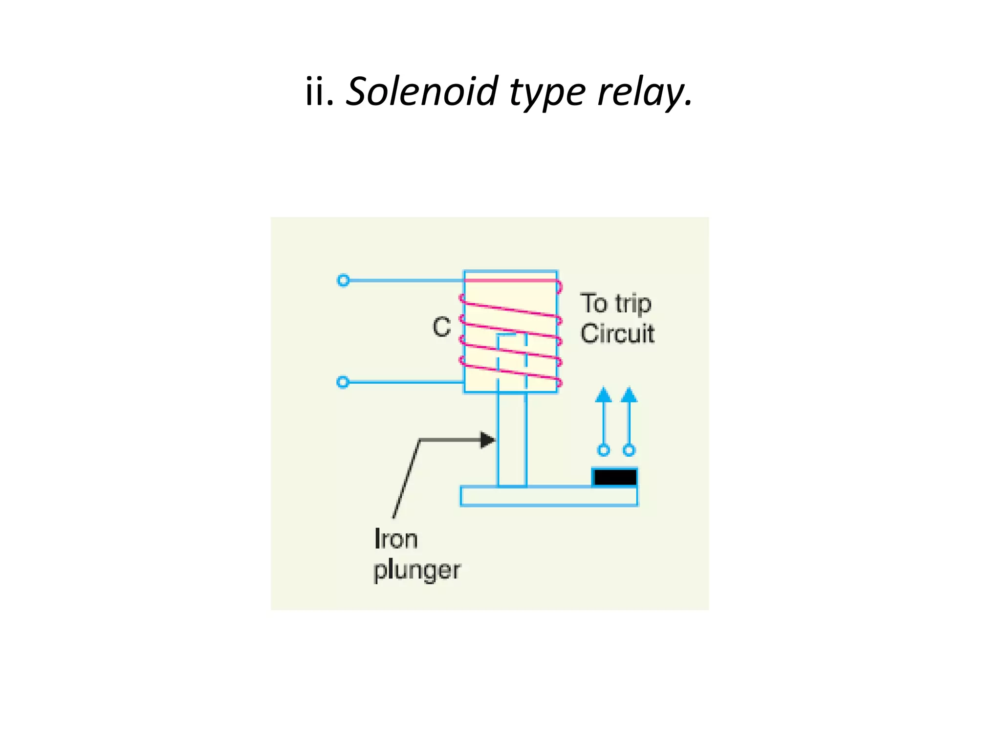
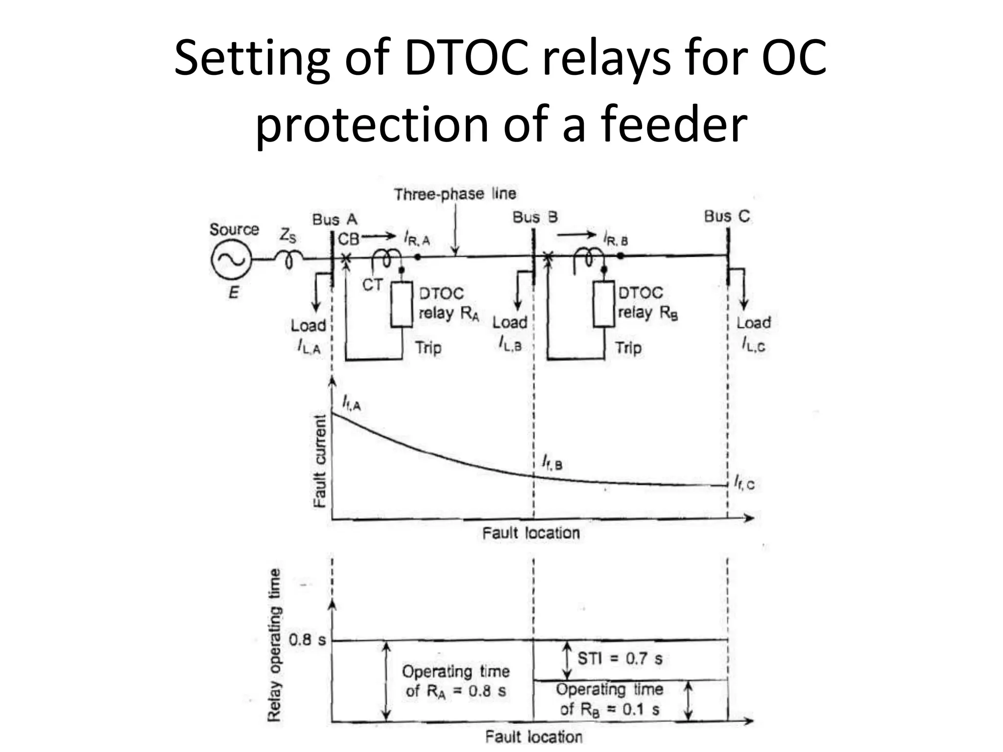
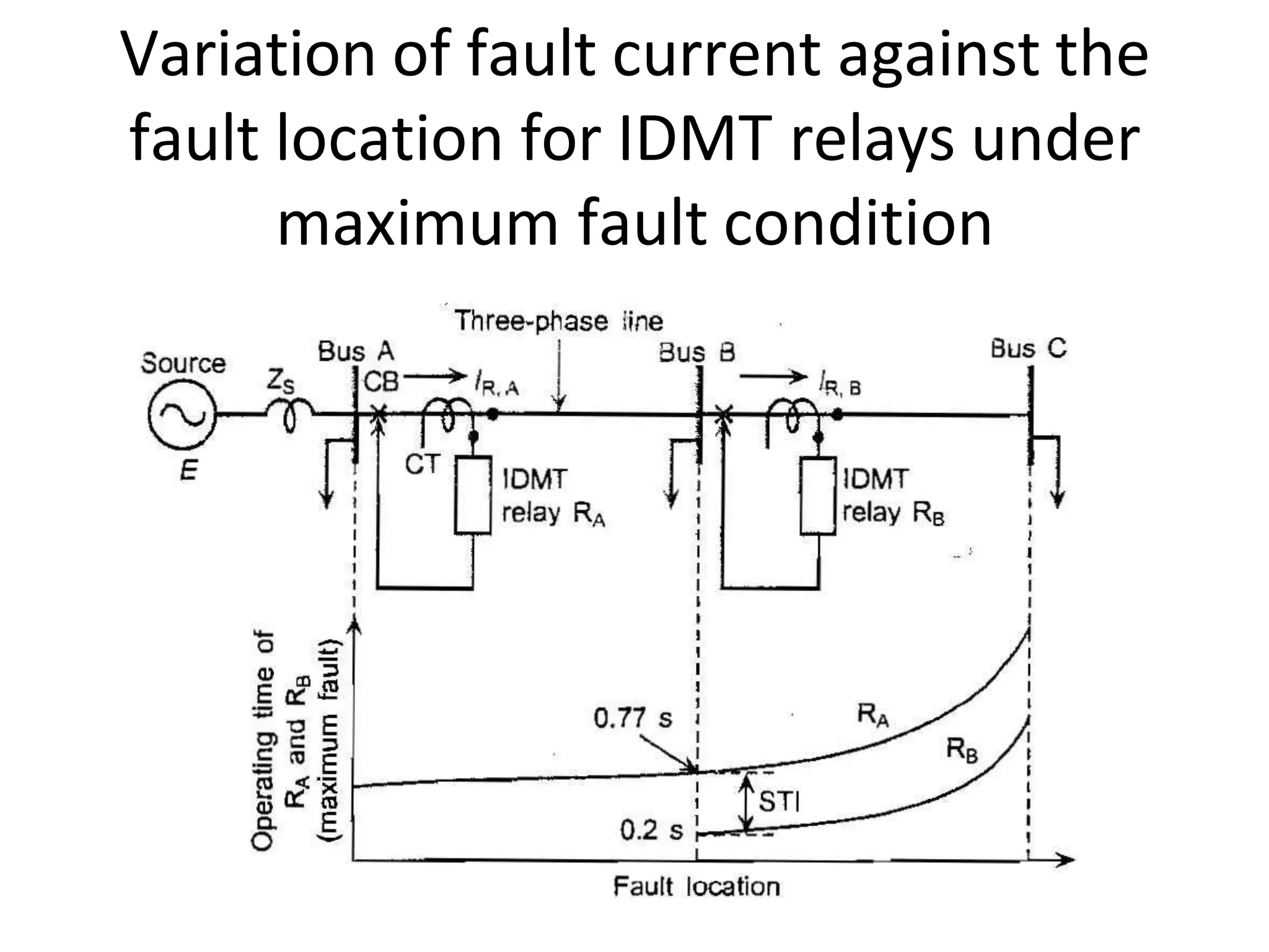
Over-current protection of
transmission lines
Fuse
Thermal Relays
• Bimetallic Relay
Over-current Relay
Important terms
• Pick up current: It is the
minimum current in the
relay coil at which the
relay starts to operate.
• Current setting:
Pick-up current = Rated
secondary current of
C.T. × Current setting
Plug-setting multiplier (P.S.M.):
• P.S.M. = Fault current in relay coil / Pick - up
current
= Fault current in relay coil/
(Rated secondary current of CT × Current
setting)
Time setting multiplier:
Time/ P.S.M curve:
Relay Timing
• Instantaneous over-current relay
Definite time over-current relay
• Inverse time over-current relay
• Inverse definite minimum time (IDMT) over-current
relay
Very Inverse type over-current relay
Extremely inverse type over-current
relay
Inverse definite minimum type relay Characteristics
(TMS=1.0)
Electromagnetic Attraction Relays
i. Attracted armature type relay
ii. Solenoid type relay.
iii. Balanced beam type relay.
Induction type Relay
Shaded pole structure
Watt-hour meter structure
Induction cup structure
Application of DTOC Relays for
protection of a distribution feeder
Plug setting of DTOC relay
Time setting of DTOC relay
Purpose and setting of relays
Setting of DTOC relays for OC
protection of a feeder
Application of IDMT relay on a
distribution feeder
Variation of fault current against the
fault location for IDMT relays under
maximum fault condition
Choice between IDMT and DTOC relays
Earth-Fault Protection
Residually connected earth-fault relay
Connection of CTs for earth fault
protection
Earth fault relay connected in neutral
to earth circuit
Combined earth-fault and phase fault
protection
Protection of a Three Phase Feeder
Over-current protection of a three
phase feeder
Two phase fault relays and one ground
fault relay for over-current protection of a
three phase feeder
Directional Over-current relay
Characteristics of directional over-
current relay
Over current protection (1).pptx

Over current protection (1).pptx