Production of Blue Hydrogen from Biomethane and its Applications.pptx
•Download as PPTX, PDF•
0 likes•94 views
This presentation covers topics to describe what is blue hydrogen, how it is different , methods of producing it, economics feasibility, and its applications.
Report
Share
Report
Share

Recommended
(HTS) High Temperature Shift Catalyst (VSG-F101) - Comprehensiev Overview
The document discusses improvements in high temperature shift catalysts. It describes the characteristics and operational issues of traditional HTS catalysts and how the new VULCAN Series VSG-F101 catalyst has addressed these issues through modifications to its microstructure and composition. The VSG-F101 has shown improved activity, strength, and resistance to thermal and mechanical stresses during plant upsets compared to previous catalysts.
Reduction and Start-Up of Steam Reforming Catalyst
The document provides guidelines for safely starting up and reducing steam reforming catalyst. It discusses warm-up procedures to avoid condensation, reducing the catalyst with hydrogen or hydrocarbons, and gradually introducing feedstock. It also summarizes a case study where overfiring during start-up led to tube failures due to much higher than normal temperatures as a result of deviations from proper procedures.
Secondary Reforming Flowsheets
This document discusses secondary reforming in ammonia and hydrogen/syngas production. It explains that ammonia plants commonly use a secondary reformer fired with air, as the nitrogen from air is useful for ammonia synthesis. However, hydrogen/syngas plants less commonly use secondary reforming because nitrogen cannot be tolerated in the process and an air separation unit may not be available or affordable to provide oxygen. The document outlines the key components of secondary reformers - the burner design, mixing volume, and catalyst - which must all be optimized to improve performance.
Gas Heated Reforming - An Overview
"There is a real gain to be made by achieving a lower exit temperature and better equilibrium conversion at the outlet of the reactor. "
Methanol Reformer Designs
Three major types of reformer
Each tackles the duty in different ways
No clear best choice
Choice dictated by Contractor history
101 Things That Can Go Wrong on a Primary Reformer - Best Practices Guide
This document discusses common problems that can occur in primary reformers and associated equipment. It identifies issues that can lead to plant shutdowns or efficiency losses, grouping them under catalysts, tubes, furnace boxes, burners, flue gas ducts, headers, and refractories. Some examples discussed include carbon formation, tube overheating, flame impingement, leaks in air preheaters, combustion air maldistribution, and damage to coffins. The document provides an overview of these issues to improve plant reliability over its lifespan.
Tube Wall Temperature Measurement On Steam Reformers - Best Practices
GBH Enterprises provides guidance on best practices for measuring tube wall temperatures in steam reformers using optical pyrometers. It is important to measure temperatures accurately to prevent overheating tubes while maximizing plant efficiency. GBH recommends taking multiple temperature and background readings per tube using handheld pyrometers and an emissivity correction factor. Safety precautions like protective equipment are also advised. Detailed procedures are outlined for top-fired, side-fired and terrace wall furnace configurations.
Reduction & Startup of Pre-reforming Catalysts
This document discusses the procedures for reducing and starting up a pre-reforming catalyst. It describes drying the catalyst at 175-250°C for 4-24 hours using nitrogen or natural gas below 200°C. The catalyst is then heated to its operating temperature of 400°C using nitrogen, with warming rates between 150-170°C per hour. Once hot, 10% hydrogen is added followed by steam to start the process. For unreduced catalyst, it takes 12-16 hours at 450-500°C with increasing hydrogen levels to fully reduce the nickel oxide catalyst. The objectives and planned installation of a new pre-reformer during a turnaround are also summarized.
High Temperature Shift Catalyst Reduction Procedure
High Temperature Shift Catalyst Reduction Procedure
The catalyst, as supplied, is Fe2O3. This reduces to the active form, Fe3O4, in the presence of hydrogen when process gas is admitted to the reactor.
1. The mildly exothermic reactions are:
3 Fe2O3 + H2 ========= 2 Fe3O4 + H2O
3 Fe2O3 + CO ========= 2 Fe3O4 + CO2
Episode 3 : Production of Synthesis Gas by Steam Methane Reforming
Episode 3 : Production of Synthesis Gas by Steam Methane Reforming
History of Synthesis Gas
In 1780, Felice Fontana discovered that combustible gas develops if water vapor is passed over carbon at temperatures over 500 °C. This CO and H2 containing gas was called water gas and mainly used for lighting purposes in the19th century.
As of the beginning of the 20th century, H2/CO-mixtures were used for syntheses of hydrocarbons and then, as a consequence, also called synthesis gas.
Haber and Bosch discovered the synthesis of ammonia from H2 and N2 in 1910 and the first industrial ammonia synthesis plant was commissioned in 1913.
The production of liquid hydrocarbons and oxygenates from syngas conversion over iron catalysts was discovered in 1923 by Fischer and Tropsch.
Much of the syngas conversion processes were being developed in Germany during the first and second world wars at a time when natural resources were becoming scare and alternative routes for hydrogen production, ammonia synthesis, and transportation fuels were a necessity.
In 1943/44, this was applied for large-scale production of artificial fuels from synthesis gas in Germany.
Benfield system
This document provides information on the Benfield process for removing carbon dioxide from gas streams. It discusses key aspects of the process including:
- Absorption of CO2 into a potassium carbonate solution and regeneration of the solution by heating.
- Use of an activator like DEA to improve CO2 absorption.
- Comparison with other CO2 removal processes like Rectisol and considerations for process selection.
- Parameters that affect the absorption and regeneration steps like pressure, temperature, and flow rates.
- Causes and prevention of corrosion in the system through vanadium addition and factors that can cause foaming of the solution.
Steam Reforming - A Comprehensive Review
Equilibrium, Approach & Kinetics
Carbon Laydown
Potash Doping
Catalyst Loading
Pigtail Nippers
GHR & AGHR
Secondary Reforming
Metal Dusting
Steam Reforming - Common Problems
Examination of some of the common problems that occur on steam reformers
Analyze problems associated with
Catalyst
Tubes
Reformer Design
Common Problems
- Poisoning
- Carbon formation
- Tunnel problems
- Air leaks
- Tube failures
Less common ones include
- Tunnel Port Effect
- Flue gas Mal-distribution
CATALYST PROBLEMS
- Poisoning
- Hot Bands
- Carbon Formation
- Hot Banding & Tube Appearances
- Nipped Tubes - The Domino Effect
- Catalyst Loading
- Affect of Delta P Variation
- Catalyst Settling
- Catalyst Breakage
HARDWARE PROBLEMS
- Foster Wheeler Terraced Wall
- Mal distribution
- Collapsed Tunnels
- Effect of Removing Coffins
- Undersized Fans
- Other Hardware Problems
OPERATIONAL PROBLEMS
- Flame Impingement
- After Burning
- Catalyst Milling
- Catalyst Breakage
- Catalyst Color Variation
- Bowed Tubes
- Refractory Problems
- Other Operational Problems
Normal Operation of Steam Reformers on Hydrogen Plants
Typical controlled variables
Plant data analysis
Approach to equilibrium
Prediction of remaining catalyst life
Tube wall temperature measurement
Feedstock Purfication in Hydrogen Plants
1. Introduction reasons for purification, types of poisons, and typical systems
2. Hydrogenation
3. Dechlorination
4. Sulfur Removal
5. Purification system start-up and shut-down
Theory and Practice of Steam Reforming
Steam reforming reactions
Steam reforming catalyst
Equilibrium considerations
Carbon formation
Poisoning
Steam reformer modeling
Pre-reforming
Post-reforming
Ammonia Plant - Secondary Reforming
Why have a Secondary Reformer ?
Need nitrogen to make ammonia
Wish to make primary as small as possible
Wish to minimise methane slip since methane is an inert in the ammonia synthesis loop
Other methods of achieving this
Braun Purifier process
Can address all these with an air blown secondary
Aiche 42-024-primary reformer failure- agrium
The primary reformer at Agrium's Fort Saskatchewan Nitrogen Operations experienced a massive failure following a routine startup. Almost all 260 catalyst tubes in the radiant section failed, and the air-steam preheat coil was damaged, resulting in lost production. An investigation found that additional burners were lit without checks of flame impingement or tube temperature, causing the flue gas temperature to reach over 1,000°C and melt the tubes. Over 50% of tubes failed, with molten metal solidifying in the catalyst. Kellogg Brown and Root were contracted to replace all failed components and repair the furnace to restore production as soon as possible.
Steam Reforming - Types of Reformer Design
Four main types
Types of Reformer Design
Pre reformers
Primary reformers
Main different designs
Secondary reformers
Compact reformers
Key Considerations for a Reforming Unit Revamp
Revamp objectives
Revamp Philosophy
Revamp options
Semi-Regenerative Reforming Unit
Typical Flow Scheme
Continuous Reforming Unit
Typical Flow Scheme
Revamp to Hybrid Operation
What may be achieved?
Typical C5+ Yield at Decreasing Pressure
Changes Required for Full Conversion
Typical Benefits of Full Conversion
Revamping of Existing Continuous Reforming Units
Fired Heaters Revamp
Burners
Reactor Options
Regeneration Section
Summary
Water-Gas-Shift Reactor Loading & Unloading Considerations
(WGS) Water Gas Shift - Loading & Unloading
High Temperature Shift & Low Temperature Shift
Fixed Beds: Catalyst Discharge
(LTS) Low Temperature Shift Catalyst - Comprehensive Overview
The document discusses low temperature shift catalysts used in hydrogen production plants. It describes the purpose of low temperature shift catalysts in further converting carbon monoxide to carbon dioxide to improve hydrogen yield and remove impurities. It then covers the chemistry, typical operating conditions, factors influencing catalyst activity like temperature profile and poisons, and byproduct formation issues. The document promotes the VSG-C111/112 series as superior catalysts, highlighting their resistance to poisons like sulfur and chloride, low methanol byproduct formation, high activity, and strength properties.
Burner Design, Operation and Maintenance on Ammonia Plants
The document discusses burner design, operation, and maintenance on ammonia plants. It covers reformer burner types and designs, including premix and staged burners. It also addresses combustion characteristics like excess air and fuel viscosity effects. Maintenance best practices like checking burner pressures and atomizing steam temperatures are emphasized. Low NOx equipment uses techniques like staged air, fuel, and flue gas recirculation to reduce emissions. Good combustion requires attention to design, operation, maintenance, and partnership among related roles.
Pre-reformer Operations Technical Supplement
This document discusses operating pre-reformers at high temperatures and the associated benefits and drawbacks. It notes that while higher temperatures allow for better thermal efficiency and feedstock flexibility in reformers, they can also cause hydrothermal sintering of catalysts over time from high heat and steam. The document provides guidelines for startup, reduction, and operation of pre-reformer catalysts to maximize performance while mitigating sintering risks.
Catalyst Breakage in Reformer Tubes
Introduction
Catalyst breakage is a well known phenomena that occurs during operation and transients such as reformer trips, whether this be due to,
• Normal in service breakage,
• Breakage due to carbon formation/removal,
• Breakage due to steam condensation or carry over,
• Breakage during a trip.
The effect of catalyst breakage can be observed in a number of ways,
• Hot bands,
• Speckling and giraffe necking,
• Catalyst breakage and settling.
The Benefits and Disadvantages of Potash in Steam Reforming
Why do we include potash ?
What are the benefits ?
What are the disadvantages ?
Catalyst Deactivation
Carbon Deposition : Thermodynamics & Kinetics
Carbon formation margin
Reaction chemistry (Tube inlet)
Hydrocarbons undergo cracking reactions on hot surfaces at the tube inlet
Products of catalytic cracking reactions can form polymeric carbon
Start Up Procedures for Primary Reforming Catalyst
VULCAN Series VSG-Z101 Primary Reforming
Initial Catalyst Reduction
Activating (reducing) the catalyst involves changing the nickel oxide to nickel, represented by:
NiO + H2 <==========> Ni + H2O
Natural gas is typically used as the hydrogen source. When it is, the catalyst reduction and putting the reformer on-line are accompanied in the same step.
Catalyst Catastrophes in Syngas Production - I
Catalyst Catastrophes in Syngas Production - I
The Hazards
Review incidents by reactor
Purification….
Through the various unit operations to
Ammonia synthesis
Nickel Carbonyl
Pre-reduced catalysts
Discharging catalysts
Conclusion
IRJET- Hydrogen Fuel Cell
The document discusses hydrogen fuel cells, including:
1) Hydrogen fuel cells convert chemical energy directly into electrical energy and can provide clean renewable energy for vehicles and stationary power applications.
2) The main methods for producing hydrogen include steam reforming of natural gas, coal gasification, and electrolysis of water. Hydrogen is then stored using compression, liquefaction, or solid-state storage before being delivered via pipelines or cryogenic tanks.
3) Hydrogen is used as fuel in various fuel cell types, with proton exchange membrane fuel cells being a major candidate for automotive use due to their high efficiency and low weight. However, hydrogen fuel cells still face challenges with costs and durability that need to be addressed
Carbon Capture & Storage - Options For India
The presentation will try to answer a few key questions related to the cost, technology, scalability and risks involved in widespread deployment of the carbon capture and sequestration technology.
More Related Content
What's hot
High Temperature Shift Catalyst Reduction Procedure
High Temperature Shift Catalyst Reduction Procedure
The catalyst, as supplied, is Fe2O3. This reduces to the active form, Fe3O4, in the presence of hydrogen when process gas is admitted to the reactor.
1. The mildly exothermic reactions are:
3 Fe2O3 + H2 ========= 2 Fe3O4 + H2O
3 Fe2O3 + CO ========= 2 Fe3O4 + CO2
Episode 3 : Production of Synthesis Gas by Steam Methane Reforming
Episode 3 : Production of Synthesis Gas by Steam Methane Reforming
History of Synthesis Gas
In 1780, Felice Fontana discovered that combustible gas develops if water vapor is passed over carbon at temperatures over 500 °C. This CO and H2 containing gas was called water gas and mainly used for lighting purposes in the19th century.
As of the beginning of the 20th century, H2/CO-mixtures were used for syntheses of hydrocarbons and then, as a consequence, also called synthesis gas.
Haber and Bosch discovered the synthesis of ammonia from H2 and N2 in 1910 and the first industrial ammonia synthesis plant was commissioned in 1913.
The production of liquid hydrocarbons and oxygenates from syngas conversion over iron catalysts was discovered in 1923 by Fischer and Tropsch.
Much of the syngas conversion processes were being developed in Germany during the first and second world wars at a time when natural resources were becoming scare and alternative routes for hydrogen production, ammonia synthesis, and transportation fuels were a necessity.
In 1943/44, this was applied for large-scale production of artificial fuels from synthesis gas in Germany.
Benfield system
This document provides information on the Benfield process for removing carbon dioxide from gas streams. It discusses key aspects of the process including:
- Absorption of CO2 into a potassium carbonate solution and regeneration of the solution by heating.
- Use of an activator like DEA to improve CO2 absorption.
- Comparison with other CO2 removal processes like Rectisol and considerations for process selection.
- Parameters that affect the absorption and regeneration steps like pressure, temperature, and flow rates.
- Causes and prevention of corrosion in the system through vanadium addition and factors that can cause foaming of the solution.
Steam Reforming - A Comprehensive Review
Equilibrium, Approach & Kinetics
Carbon Laydown
Potash Doping
Catalyst Loading
Pigtail Nippers
GHR & AGHR
Secondary Reforming
Metal Dusting
Steam Reforming - Common Problems
Examination of some of the common problems that occur on steam reformers
Analyze problems associated with
Catalyst
Tubes
Reformer Design
Common Problems
- Poisoning
- Carbon formation
- Tunnel problems
- Air leaks
- Tube failures
Less common ones include
- Tunnel Port Effect
- Flue gas Mal-distribution
CATALYST PROBLEMS
- Poisoning
- Hot Bands
- Carbon Formation
- Hot Banding & Tube Appearances
- Nipped Tubes - The Domino Effect
- Catalyst Loading
- Affect of Delta P Variation
- Catalyst Settling
- Catalyst Breakage
HARDWARE PROBLEMS
- Foster Wheeler Terraced Wall
- Mal distribution
- Collapsed Tunnels
- Effect of Removing Coffins
- Undersized Fans
- Other Hardware Problems
OPERATIONAL PROBLEMS
- Flame Impingement
- After Burning
- Catalyst Milling
- Catalyst Breakage
- Catalyst Color Variation
- Bowed Tubes
- Refractory Problems
- Other Operational Problems
Normal Operation of Steam Reformers on Hydrogen Plants
Typical controlled variables
Plant data analysis
Approach to equilibrium
Prediction of remaining catalyst life
Tube wall temperature measurement
Feedstock Purfication in Hydrogen Plants
1. Introduction reasons for purification, types of poisons, and typical systems
2. Hydrogenation
3. Dechlorination
4. Sulfur Removal
5. Purification system start-up and shut-down
Theory and Practice of Steam Reforming
Steam reforming reactions
Steam reforming catalyst
Equilibrium considerations
Carbon formation
Poisoning
Steam reformer modeling
Pre-reforming
Post-reforming
Ammonia Plant - Secondary Reforming
Why have a Secondary Reformer ?
Need nitrogen to make ammonia
Wish to make primary as small as possible
Wish to minimise methane slip since methane is an inert in the ammonia synthesis loop
Other methods of achieving this
Braun Purifier process
Can address all these with an air blown secondary
Aiche 42-024-primary reformer failure- agrium
The primary reformer at Agrium's Fort Saskatchewan Nitrogen Operations experienced a massive failure following a routine startup. Almost all 260 catalyst tubes in the radiant section failed, and the air-steam preheat coil was damaged, resulting in lost production. An investigation found that additional burners were lit without checks of flame impingement or tube temperature, causing the flue gas temperature to reach over 1,000°C and melt the tubes. Over 50% of tubes failed, with molten metal solidifying in the catalyst. Kellogg Brown and Root were contracted to replace all failed components and repair the furnace to restore production as soon as possible.
Steam Reforming - Types of Reformer Design
Four main types
Types of Reformer Design
Pre reformers
Primary reformers
Main different designs
Secondary reformers
Compact reformers
Key Considerations for a Reforming Unit Revamp
Revamp objectives
Revamp Philosophy
Revamp options
Semi-Regenerative Reforming Unit
Typical Flow Scheme
Continuous Reforming Unit
Typical Flow Scheme
Revamp to Hybrid Operation
What may be achieved?
Typical C5+ Yield at Decreasing Pressure
Changes Required for Full Conversion
Typical Benefits of Full Conversion
Revamping of Existing Continuous Reforming Units
Fired Heaters Revamp
Burners
Reactor Options
Regeneration Section
Summary
Water-Gas-Shift Reactor Loading & Unloading Considerations
(WGS) Water Gas Shift - Loading & Unloading
High Temperature Shift & Low Temperature Shift
Fixed Beds: Catalyst Discharge
(LTS) Low Temperature Shift Catalyst - Comprehensive Overview
The document discusses low temperature shift catalysts used in hydrogen production plants. It describes the purpose of low temperature shift catalysts in further converting carbon monoxide to carbon dioxide to improve hydrogen yield and remove impurities. It then covers the chemistry, typical operating conditions, factors influencing catalyst activity like temperature profile and poisons, and byproduct formation issues. The document promotes the VSG-C111/112 series as superior catalysts, highlighting their resistance to poisons like sulfur and chloride, low methanol byproduct formation, high activity, and strength properties.
Burner Design, Operation and Maintenance on Ammonia Plants
The document discusses burner design, operation, and maintenance on ammonia plants. It covers reformer burner types and designs, including premix and staged burners. It also addresses combustion characteristics like excess air and fuel viscosity effects. Maintenance best practices like checking burner pressures and atomizing steam temperatures are emphasized. Low NOx equipment uses techniques like staged air, fuel, and flue gas recirculation to reduce emissions. Good combustion requires attention to design, operation, maintenance, and partnership among related roles.
Pre-reformer Operations Technical Supplement
This document discusses operating pre-reformers at high temperatures and the associated benefits and drawbacks. It notes that while higher temperatures allow for better thermal efficiency and feedstock flexibility in reformers, they can also cause hydrothermal sintering of catalysts over time from high heat and steam. The document provides guidelines for startup, reduction, and operation of pre-reformer catalysts to maximize performance while mitigating sintering risks.
Catalyst Breakage in Reformer Tubes
Introduction
Catalyst breakage is a well known phenomena that occurs during operation and transients such as reformer trips, whether this be due to,
• Normal in service breakage,
• Breakage due to carbon formation/removal,
• Breakage due to steam condensation or carry over,
• Breakage during a trip.
The effect of catalyst breakage can be observed in a number of ways,
• Hot bands,
• Speckling and giraffe necking,
• Catalyst breakage and settling.
The Benefits and Disadvantages of Potash in Steam Reforming
Why do we include potash ?
What are the benefits ?
What are the disadvantages ?
Catalyst Deactivation
Carbon Deposition : Thermodynamics & Kinetics
Carbon formation margin
Reaction chemistry (Tube inlet)
Hydrocarbons undergo cracking reactions on hot surfaces at the tube inlet
Products of catalytic cracking reactions can form polymeric carbon
Start Up Procedures for Primary Reforming Catalyst
VULCAN Series VSG-Z101 Primary Reforming
Initial Catalyst Reduction
Activating (reducing) the catalyst involves changing the nickel oxide to nickel, represented by:
NiO + H2 <==========> Ni + H2O
Natural gas is typically used as the hydrogen source. When it is, the catalyst reduction and putting the reformer on-line are accompanied in the same step.
Catalyst Catastrophes in Syngas Production - I
Catalyst Catastrophes in Syngas Production - I
The Hazards
Review incidents by reactor
Purification….
Through the various unit operations to
Ammonia synthesis
Nickel Carbonyl
Pre-reduced catalysts
Discharging catalysts
Conclusion
What's hot (20)
High Temperature Shift Catalyst Reduction Procedure
High Temperature Shift Catalyst Reduction Procedure
Episode 3 : Production of Synthesis Gas by Steam Methane Reforming
Episode 3 : Production of Synthesis Gas by Steam Methane Reforming
Normal Operation of Steam Reformers on Hydrogen Plants
Normal Operation of Steam Reformers on Hydrogen Plants
Water-Gas-Shift Reactor Loading & Unloading Considerations
Water-Gas-Shift Reactor Loading & Unloading Considerations
(LTS) Low Temperature Shift Catalyst - Comprehensive Overview
(LTS) Low Temperature Shift Catalyst - Comprehensive Overview
Burner Design, Operation and Maintenance on Ammonia Plants
Burner Design, Operation and Maintenance on Ammonia Plants
The Benefits and Disadvantages of Potash in Steam Reforming
The Benefits and Disadvantages of Potash in Steam Reforming
Start Up Procedures for Primary Reforming Catalyst
Start Up Procedures for Primary Reforming Catalyst
Similar to Production of Blue Hydrogen from Biomethane and its Applications.pptx
IRJET- Hydrogen Fuel Cell
The document discusses hydrogen fuel cells, including:
1) Hydrogen fuel cells convert chemical energy directly into electrical energy and can provide clean renewable energy for vehicles and stationary power applications.
2) The main methods for producing hydrogen include steam reforming of natural gas, coal gasification, and electrolysis of water. Hydrogen is then stored using compression, liquefaction, or solid-state storage before being delivered via pipelines or cryogenic tanks.
3) Hydrogen is used as fuel in various fuel cell types, with proton exchange membrane fuel cells being a major candidate for automotive use due to their high efficiency and low weight. However, hydrogen fuel cells still face challenges with costs and durability that need to be addressed
Carbon Capture & Storage - Options For India
The presentation will try to answer a few key questions related to the cost, technology, scalability and risks involved in widespread deployment of the carbon capture and sequestration technology.
Techno-economic assessment and global sensitivity analysis for biomass-based ...
Techno-economic assessment and global sensitivity analysis for biomass-based ...UK Carbon Capture and Storage Research Centre
Techno-economic assessment and global sensitivity analysis for biomass-based CO2 capture storage and utilisation (CCSU) technologies - presentation by Maria Botero in the Biomass CCS session at the UKCCSRC Cardiff Biannual Meeting, 10-11 September 2014Carbon Capture and Storage
1. The document analyzes the role of carbon capture, utilization and storage (CCUS) in decarbonizing heavy industry through long-term energy system modeling.
2. It finds that CCUS faces strong competition from hydrogen in steel but is essential in cement. Carbon capture could help produce clean fuels through utilization but clean production routes may be more important than more capture units for deep decarbonization.
3. An 80% industry decarbonization policy has twice the total annual cost as pathways aligned with the Paris Agreement goals.
Indian oil r&d whec 2018
Dr. SSV Ramakumar presented on challenges for the hydrogen economy and IndianOil's initiatives in hydrogen and fuel cells. Key points included:
- India has a population of 1.27 billion and is the 3rd largest economy in PPP terms, with strong GDP growth of 7.3% in 2018.
- IndianOil is researching hydrogen production from various domestic resources like natural gas, biomass, and solar energy to reduce costs below $4/kg.
- Challenges for hydrogen include developing affordable production and storage technologies to enable its use in transportation and achieve India's climate change commitments.
- IndianOil is working on compact reforming, biomass gasification,
Mg(OH)2 (& high-value by-products) from Serpentines & Olivines for scalable l...
Mg(OH)2 (& high-value by-products) from Serpentines & Olivines for scalable l...UK Carbon Capture and Storage Research Centre
CCC is developing a process to sequester CO2 from flue gases by converting it to magnesium carbonates using magnesium hydroxide produced from serpentine and olivine minerals. The process involves two steps: (1) an alkaline digestion that converts minerals like serpentine and olivine to magnesium hydroxide and silica, and (2) direct wet scrubbing to react the magnesium hydroxide with low-pressure CO2 to form soluble magnesium bicarbonate or solid magnesium carbonate. This process could sequester CO2 on a gigatonne scale at a low energy cost while also producing valuable byproducts from the minerals.Hydrogen Production Cost Analysis rc pdf2.pdf
TOP 10 HYDROGEN PRODUCTION COST OPTIMIZATION TECHNIQUES
Hydrogen production cost analysis is crucial for understanding the economic viability of hydrogen as an energy source. But do you know what are those Cost Optimization techniques, how to identify, which phase to implement?
Explore the top 10 Hydrogen Production Cost Optimization Techniques!
1. How can renewable energy integration be leveraged to optimize hydrogen production costs?
2. What advancements in coal gasification technologies can contribute to cost optimization in hydrogen production?
3. What are the potential cost-saving benefits of technological innovation in hydrogen production processes?
4. Deep dive analysis on various cost optimization techniques for Steam Methane Reforming (SMR)
5. How can the utilization of carbon capture and utilization (CCU) technologies in SMR reduce greenhouse gas emissions and potentially generate additional revenue streams?
6. What strategies can be implemented to optimize the cost efficiency of electrolysis for hydrogen production?
Hydrogen is now widely recognized as a promising clean energy carrier due to the global shift towards sustainable energy sources. It is critical to comprehend the complexities of hydrogen production costs as demand for the gas rises. This article explores the economic factors that will influence the future of this essential energy vector by providing a thorough examination of the expenses associated with producing hydrogen.
Carbon capture and storage
Carbon Capture and Storage (CCS) aims to reduce CO2 emissions from large sources like power plants. It involves three steps: CO2 capture using technologies like post-combustion, pre-combustion, or oxy-fuel combustion; transportation mostly via pipelines; and geological storage in oil/gas reservoirs, unmineable coal beds, or saline aquifers. Challenges include the costs of infrastructure and risk of leakages from transportation or storage affecting the environment. CCS could help mitigate climate change but drawbacks need to be addressed.
184_presentation_20210606_132102.pptx
1. The document analyzes scenarios for decarbonizing industry using carbon capture, utilization and storage (CCUS) technologies through 2100 using an integrated assessment model.
2. Results show hydrogen competing with CCS in steel production, while CCS is essential for cement plants alongside less clinker-intensive cements.
3. Carbon capture and utilization plays a minor role compared to storage but can significantly contribute to clean fuel production.
ID-109.pdf
This document presents an assessment of the performance and costs of CO2-based Next Generation Geothermal Power (NGP) systems. It discusses the thermodynamic and economic evaluations that were conducted, including cycle designs, performance results, sensitivities to parameters, and initial cost estimates. The analysis shows that NGP systems can generate 2.5-3.4 times higher net power output than conventional brine-based geothermal systems under baseline conditions. Preliminary levelized cost of electricity estimates for NGP place it in the range of conventional generation technologies and competitive with solar plus storage. Further research and demonstration are needed to advance the technology.
Hydrogen Production Cost Analysis recreate content pdf.pdf
TOP 10 HYDROGEN PRODUCTION COST OPTIMIZATION TECHNIQUES
Hydrogen production cost analysis is crucial for understanding the economic viability of hydrogen as an energy source. But do you know what are those Cost Optimization techniques, how to identify, which phase to implement?
Explore the top 10 Hydrogen Production Cost Optimization Techniques!
1. How can renewable energy integration be leveraged to optimize hydrogen production costs?
2. What advancements in coal gasification technologies can contribute to cost optimization in hydrogen production?
3. What are the potential cost-saving benefits of technological innovation in hydrogen production processes?
4. Deep dive analysis on various cost optimization techniques for Steam Methane Reforming (SMR)
5. How can the utilization of carbon capture and utilization (CCU) technologies in SMR reduce greenhouse gas emissions and potentially generate additional revenue streams?
6. What strategies can be implemented to optimize the cost efficiency of electrolysis for hydrogen production?
Green Hydrogen Production:
The utilization of renewable energy in the electrolysis process ensures that the entire hydrogen production chain contributes to the global efforts to combat climate change. Green hydrogen production contributes to energy independence by leveraging locally available renewable resources. Several countries are taking bold steps to promote green hydrogen production. Green hydrogen production stands at the forefront of the renewable energy revolution, offering a clean and sustainable alternative to traditional hydrogen production methods.
Calash Hydrogen Outlook
As a clean burning fuel, Hydrogen is expected to play an important role in the energy transition, particularly for hard to abate sectors; however, it should only be deployed where appropriate, and the potential electricity requirement for green hydrogen should also be considered
Electricity Production By Waste Materials
This document discusses electricity production from waste materials via biomass gasification. The process involves converting biomass waste into a combustible gas in a gasifier, and then using the gas to power a generator set. The gasifier thermo-chemically converts solid biomass fuels into a clean syngas. This syngas can then be used for cooking or generating electricity by feeding it into a diesel generator set. The system has advantages such as reducing pollution and recycling waste materials while producing electricity in a renewable way. However, biomass gasification also faces challenges related to capital costs and fuel flexibility.
A REVIEW: CARBON CAPTURE AND SEQUESTRATION (CCS) IN INDIA
In 21st century research on carbon capture and sequestration is totally based on optimizing the process of capture either by increasing the capture efficiency or by reducing the work input (energy consumption) in the process of capturing the carbon dioxide. This review article is prime focused on the present scenario of global greenhouse gas (GHG) emissions; aspects of new world with CCS with its merits-demerits and new emerging technological implementations.
CO2 Capture - Jon Gibbins, UKCCSRC, at the UKCCSRC ECR Winter School 2015
CO2 Capture - Jon Gibbins, UKCCSRC, at the UKCCSRC ECR Winter School 2015UK Carbon Capture and Storage Research Centre
The document discusses carbon capture technologies that are likely to appear in future phases of carbon capture and storage (CCS) deployment. It provides information on various carbon capture technologies including post-combustion capture using solvents like amines, pre-combustion capture through integrated gasification combined cycle (IGCC) plants, and oxy-fuel combustion. Examples of large-scale CCS projects currently in operation or development are also mentioned, such as the Kemper County energy facility and White Rose CCS project.NEWWEST PPT JAN6.pptx
Green hydrogen has the potential to contribute significantly to India's decarbonization efforts. It can be produced through the electrolysis of water using renewable electricity (green hydrogen). Green hydrogen production in India is projected to reach 5 MMT per year by 2030, displacing 125 GW of renewable energy capacity. This would result in investment of Rs. 8 lakh crore and creation of over 6 lakh jobs while avoiding 50 MMT of CO2 emissions annually by 2030. The National Green Hydrogen Mission aims to support green hydrogen production and consumption through targets, incentives and initiatives to establish India as a global green hydrogen hub.
Flexibility with renewable(low-carbon) hydrogen
Flexibility with renewable hydrogen
Paul Dodds, Jana Fakhreddine & Kari Espegren, IEA ETSAP
16–17th november 2023, Turin, Italy, etsap meeting, etsap winter workshop, semi-annual meeting, november 2023, Politecnico di Torino Lingotto, Torino
Impatto dell’idrogeno verde sul sistema elettrico: quali i costi? (Bruno Cova)
The document discusses green hydrogen production and its role in energy diversification. It provides:
1) An overview of hydrogen production strategies in the US and EU, which aim to scale up renewable hydrogen electrolyzers to reduce emissions in hard to decarbonize sectors.
2) A framework for assessing the costs of different implementation scenarios for integrating green hydrogen production via electrolysis into power systems, including decentralized, transport of hydrogen, and transport of electricity approaches.
3) An analysis of applying this framework to Italy's power system and hydrogen strategy, which aims for 5GW of electrolyzers by 2030, to understand the impacts on costs and markets under various scenarios.
CCS in IAM climate stabilisation scenarios – Exploring the sensitivity to CCS...
CCS in IAM climate stabilisation scenarios – Exploring the sensitivity to CCS capture rates in ETSAP-TIAM
Renewable Natural Gas
This document provides an overview of renewable natural gas (RNG) production from sources like landfills and wastewater treatment plants. It discusses the background and reasons for increased interest in high-BTU RNG projects. Various biogas upgrading technologies like PSA, membranes, water scrubbing and cryogenics are described along with their pros and cons. Potential revenue sources for RNG projects like commodity sales, renewable fuel credits, and carbon offset markets are also outlined. The presentation concludes with a discussion of common site layouts, potential pitfalls, and contact information for the presenters.
Similar to Production of Blue Hydrogen from Biomethane and its Applications.pptx (20)
Techno-economic assessment and global sensitivity analysis for biomass-based ...
Techno-economic assessment and global sensitivity analysis for biomass-based ...
Mg(OH)2 (& high-value by-products) from Serpentines & Olivines for scalable l...
Mg(OH)2 (& high-value by-products) from Serpentines & Olivines for scalable l...
Hydrogen Production Cost Analysis recreate content pdf.pdf
Hydrogen Production Cost Analysis recreate content pdf.pdf
A REVIEW: CARBON CAPTURE AND SEQUESTRATION (CCS) IN INDIA
A REVIEW: CARBON CAPTURE AND SEQUESTRATION (CCS) IN INDIA
CO2 Capture - Jon Gibbins, UKCCSRC, at the UKCCSRC ECR Winter School 2015
CO2 Capture - Jon Gibbins, UKCCSRC, at the UKCCSRC ECR Winter School 2015
Impatto dell’idrogeno verde sul sistema elettrico: quali i costi? (Bruno Cova)
Impatto dell’idrogeno verde sul sistema elettrico: quali i costi? (Bruno Cova)
CCS in IAM climate stabilisation scenarios – Exploring the sensitivity to CCS...
CCS in IAM climate stabilisation scenarios – Exploring the sensitivity to CCS...
Recently uploaded
Kinetic studies on malachite green dye adsorption from aqueous solutions by A...
Kinetic studies on malachite green dye adsorption from aqueous solutions by A...Open Access Research Paper
Water polluted by dyestuffs compounds is a global threat to health and the environment; accordingly, we prepared a green novel sorbent chemical and Physical system from an algae, chitosan and chitosan nanoparticle and impregnated with algae with chitosan nanocomposite for the sorption of Malachite green dye from water. The algae with chitosan nanocomposite by a simple method and used as a recyclable and effective adsorbent for the removal of malachite green dye from aqueous solutions. Algae, chitosan, chitosan nanoparticle and algae with chitosan nanocomposite were characterized using different physicochemical methods. The functional groups and chemical compounds found in algae, chitosan, chitosan algae, chitosan nanoparticle, and chitosan nanoparticle with algae were identified using FTIR, SEM, and TGADTA/DTG techniques. The optimal adsorption conditions, different dosages, pH and Temperature the amount of algae with chitosan nanocomposite were determined. At optimized conditions and the batch equilibrium studies more than 99% of the dye was removed. The adsorption process data matched well kinetics showed that the reaction order for dye varied with pseudo-first order and pseudo-second order. Furthermore, the maximum adsorption capacity of the algae with chitosan nanocomposite toward malachite green dye reached as high as 15.5mg/g, respectively. Finally, multiple times reusing of algae with chitosan nanocomposite and removing dye from a real wastewater has made it a promising and attractive option for further practical applications.
原版制作(Newcastle毕业证书)纽卡斯尔大学毕业证在读证明一模一样
学校原件一模一样【微信:741003700 】《(Newcastle毕业证书)纽卡斯尔大学毕业证》【微信:741003700 】学位证,留信认证(真实可查,永久存档)原件一模一样纸张工艺/offer、雅思、外壳等材料/诚信可靠,可直接看成品样本,帮您解决无法毕业带来的各种难题!外壳,原版制作,诚信可靠,可直接看成品样本。行业标杆!精益求精,诚心合作,真诚制作!多年品质 ,按需精细制作,24小时接单,全套进口原装设备。十五年致力于帮助留学生解决难题,包您满意。
本公司拥有海外各大学样板无数,能完美还原。
1:1完美还原海外各大学毕业材料上的工艺:水印,阴影底纹,钢印LOGO烫金烫银,LOGO烫金烫银复合重叠。文字图案浮雕、激光镭射、紫外荧光、温感、复印防伪等防伪工艺。材料咨询办理、认证咨询办理请加学历顾问Q/微741003700
【主营项目】
一.毕业证【q微741003700】成绩单、使馆认证、教育部认证、雅思托福成绩单、学生卡等!
二.真实使馆公证(即留学回国人员证明,不成功不收费)
三.真实教育部学历学位认证(教育部存档!教育部留服网站永久可查)
四.办理各国各大学文凭(一对一专业服务,可全程监控跟踪进度)
如果您处于以下几种情况:
◇在校期间,因各种原因未能顺利毕业……拿不到官方毕业证【q/微741003700】
◇面对父母的压力,希望尽快拿到;
◇不清楚认证流程以及材料该如何准备;
◇回国时间很长,忘记办理;
◇回国马上就要找工作,办给用人单位看;
◇企事业单位必须要求办理的
◇需要报考公务员、购买免税车、落转户口
◇申请留学生创业基金
留信网认证的作用:
1:该专业认证可证明留学生真实身份
2:同时对留学生所学专业登记给予评定
3:国家专业人才认证中心颁发入库证书
4:这个认证书并且可以归档倒地方
5:凡事获得留信网入网的信息将会逐步更新到个人身份内,将在公安局网内查询个人身份证信息后,同步读取人才网入库信息
6:个人职称评审加20分
7:个人信誉贷款加10分
8:在国家人才网主办的国家网络招聘大会中纳入资料,供国家高端企业选择人才
一比一原版西澳大学毕业证学历证书如何办理
原版定制【微信:741003700】《西澳大学毕业证学位证成绩单》【微信:741003700】成绩单 、雅思、外壳、留信学历认证永久存档查询,采用学校原版纸张、特殊工艺完全按照原版一比一制作(包括:隐形水印,阴影底纹,钢印LOGO烫金烫银,LOGO烫金烫银复合重叠,文字图案浮雕,激光镭射,紫外荧光,温感,复印防伪)行业标杆!精益求精,诚心合作,真诚制作!多年品质 ,按需精细制作,24小时接单,全套进口原装设备,十五年致力于帮助留学生解决难题,业务范围有加拿大、英国、澳洲、韩国、美国、新加坡,新西兰等学历材料,包您满意。
【业务选择办理准则】
一、工作未确定,回国需先给父母、亲戚朋友看下文凭的情况,办理一份毕业证【Q微信741003700】文凭即可
二、回国进私企、外企、自己做生意的情况,这些单位是不查询毕业证真伪的,而且国内没有渠道去查询国外文凭的真假,也不需要提供真实教育部认证。鉴于此,办理一份毕业证【Q微信741003700】即可
三、进国企,银行,事业单位,考公务员等等,这些单位是必需要提供真实教育部认证的,办理教育部认证所需资料众多且烦琐,所有材料您都必须提供原件,我们凭借丰富的经验,快捷的绿色通道帮您快速整合材料,让您少走弯路。
留信网认证的作用:
1:该专业认证可证明留学生真实身份
2:同时对留学生所学专业登记给予评定
3:国家专业人才认证中心颁发入库证书
4:这个认证书并且可以归档倒地方
5:凡事获得留信网入网的信息将会逐步更新到个人身份内,将在公安局网内查询个人身份证信息后,同步读取人才网入库信息
6:个人职称评审加20分
7:个人信誉贷款加10分
8:在国家人才网主办的国家网络招聘大会中纳入资料,供国家高端企业选择人才
【关于价格问题(保证一手价格)】
我们所定的价格是非常合理的,而且我们现在做得单子大多数都是代理和回头客户介绍的所以一般现在有新的单子 我给客户的都是第一手的代理价格,因为我想坦诚对待大家 不想跟大家在价格方面浪费时间
对于老客户或者被老客户介绍过来的朋友,我们都会适当给一些优惠。
原版制作(Manitoba毕业证书)曼尼托巴大学毕业证学位证一模一样
学校原件一模一样【微信:741003700 】《(Manitoba毕业证书)曼尼托巴大学毕业证学位证》【微信:741003700 】学位证,留信认证(真实可查,永久存档)原件一模一样纸张工艺/offer、雅思、外壳等材料/诚信可靠,可直接看成品样本,帮您解决无法毕业带来的各种难题!外壳,原版制作,诚信可靠,可直接看成品样本。行业标杆!精益求精,诚心合作,真诚制作!多年品质 ,按需精细制作,24小时接单,全套进口原装设备。十五年致力于帮助留学生解决难题,包您满意。
本公司拥有海外各大学样板无数,能完美还原。
1:1完美还原海外各大学毕业材料上的工艺:水印,阴影底纹,钢印LOGO烫金烫银,LOGO烫金烫银复合重叠。文字图案浮雕、激光镭射、紫外荧光、温感、复印防伪等防伪工艺。材料咨询办理、认证咨询办理请加学历顾问Q/微741003700
【主营项目】
一.毕业证【q微741003700】成绩单、使馆认证、教育部认证、雅思托福成绩单、学生卡等!
二.真实使馆公证(即留学回国人员证明,不成功不收费)
三.真实教育部学历学位认证(教育部存档!教育部留服网站永久可查)
四.办理各国各大学文凭(一对一专业服务,可全程监控跟踪进度)
如果您处于以下几种情况:
◇在校期间,因各种原因未能顺利毕业……拿不到官方毕业证【q/微741003700】
◇面对父母的压力,希望尽快拿到;
◇不清楚认证流程以及材料该如何准备;
◇回国时间很长,忘记办理;
◇回国马上就要找工作,办给用人单位看;
◇企事业单位必须要求办理的
◇需要报考公务员、购买免税车、落转户口
◇申请留学生创业基金
留信网认证的作用:
1:该专业认证可证明留学生真实身份
2:同时对留学生所学专业登记给予评定
3:国家专业人才认证中心颁发入库证书
4:这个认证书并且可以归档倒地方
5:凡事获得留信网入网的信息将会逐步更新到个人身份内,将在公安局网内查询个人身份证信息后,同步读取人才网入库信息
6:个人职称评审加20分
7:个人信誉贷款加10分
8:在国家人才网主办的国家网络招聘大会中纳入资料,供国家高端企业选择人才
Improving the viability of probiotics by encapsulation methods for developmen...
Improving the viability of probiotics by encapsulation methods for developmen...Open Access Research Paper
The popularity of functional foods among scientists and common people has been increasing day by day. Awareness and modernization make the consumer think better regarding food and nutrition. Now a day’s individual knows very well about the relation between food consumption and disease prevalence. Humans have a diversity of microbes in the gut that together form the gut microflora. Probiotics are the health-promoting live microbial cells improve host health through gut and brain connection and fighting against harmful bacteria. Bifidobacterium and Lactobacillus are the two bacterial genera which are considered to be probiotic. These good bacteria are facing challenges of viability. There are so many factors such as sensitivity to heat, pH, acidity, osmotic effect, mechanical shear, chemical components, freezing and storage time as well which affects the viability of probiotics in the dairy food matrix as well as in the gut. Multiple efforts have been done in the past and ongoing in present for these beneficial microbial population stability until their destination in the gut. One of a useful technique known as microencapsulation makes the probiotic effective in the diversified conditions and maintain these microbe’s community to the optimum level for achieving targeted benefits. Dairy products are found to be an ideal vehicle for probiotic incorporation. It has been seen that the encapsulated microbial cells show higher viability than the free cells in different processing and storage conditions as well as against bile salts in the gut. They make the food functional when incorporated, without affecting the product sensory characteristics.
REPORT-PRESENTATION BY CHIEF SECRETARY, ANDAMAN NICOBAR ADMINISTRATION IN OA ...
Green Tribunal Andaman
Lessons from operationalizing integrated landscape approaches
Presented by James Reed at "9th Landscape Sustainability Science Forum" on 11 May 2024
按照学校原版(UAL文凭证书)伦敦艺术大学毕业证快速办理
挂科购买【(UAL毕业证书)伦敦艺术大学毕业证】【176555708微信号】留学假毕业证成绩单、外壳、offer、留信学历认证(永久存档真实可查)采用学校原版纸张、特殊工艺完全按照原版一比一制作(包括:隐形水印,阴影底纹,钢印LOGO烫金烫银,LOGO烫金烫银复合重叠,文字图案浮雕,激光镭射,紫外荧光,温感,复印防伪)行业标杆!精益求精,诚心合作,真诚制作!多年品质 ,按需精细制作,24小时接单,全套进口原装设备,十五年致力于帮助留学生解决难题,业务范围有加拿大、英国、澳洲、韩国、美国、新加坡,新西兰等学历材料,包您满意。
【我们承诺采用的是学校原版纸张(纸质、底色、纹路),我们拥有全套进口原装设备,特殊工艺都是采用不同机器制作,仿真度基本可以达到100%,所有工艺效果都可提前给客户展示,不满意可以根据客户要求进行调整,直到满意为止!】
【业务选择办理准则】
一、工作未确定,回国需先给父母、亲戚朋友看下文凭的情况,办理一份就读学校的毕业证【微信176555708】文凭即可
二、回国进私企、外企、自己做生意的情况,这些单位是不查询毕业证真伪的,而且国内没有渠道去查询国外文凭的真假,也不需要提供真实教育部认证。鉴于此,办理一份毕业证【微信176555708】即可
三、进国企,银行,事业单位,考公务员等等,这些单位是必需要提供真实教育部认证的,办理教育部认证所需资料众多且烦琐,所有材料您都必须提供原件,我们凭借丰富的经验,快捷的绿色通道帮您快速整合材料,让您少走弯路。
留信网认证的作用:
1:该专业认证可证明留学生真实身份
2:同时对留学生所学专业登记给予评定
3:国家专业人才认证中心颁发入库证书
4:这个认证书并且可以归档倒地方
5:凡事获得留信网入网的信息将会逐步更新到个人身份内,将在公安局网内查询个人身份证信息后,同步读取人才网入库信息
6:个人职称评审加20分
7:个人信誉贷款加10分
8:在国家人才网主办的国家网络招聘大会中纳入资料,供国家高端企业选择人才
留信网服务项目:
1、留学生专业人才库服务(留信分析)
2、国(境)学习人员提供就业推荐信服务
3、留学人员区块链存储服务
→ 【关于价格问题(保证一手价格)】
我们所定的价格是非常合理的,而且我们现在做得单子大多数都是代理和回头客户介绍的所以一般现在有新的单子 我给客户的都是第一手的代理价格,因为我想坦诚对待大家 不想跟大家在价格方面浪费时间
对于老客户或者被老客户介绍过来的朋友,我们都会适当给一些优惠。
选择实体注册公司办理,更放心,更安全!我们的承诺:客户在留信官方认证查询网站查询到认证通过结果后付款,不成功不收费!
学校原版(unuk学位证书)英国牛津布鲁克斯大学毕业证硕士文凭原版一模一样
原版定制【微信:bwp0011】《(unuk学位证书)英国牛津布鲁克斯大学毕业证硕士文凭》【微信:bwp0011】成绩单 、雅思、外壳、留信学历认证永久存档查询,采用学校原版纸张、特殊工艺完全按照原版一比一制作(包括:隐形水印,阴影底纹,钢印LOGO烫金烫银,LOGO烫金烫银复合重叠,文字图案浮雕,激光镭射,紫外荧光,温感,复印防伪)行业标杆!精益求精,诚心合作,真诚制作!多年品质 ,按需精细制作,24小时接单,全套进口原装设备,十五年致力于帮助留学生解决难题,业务范围有加拿大、英国、澳洲、韩国、美国、新加坡,新西兰等学历材料,包您满意。
【业务选择办理准则】
一、工作未确定,回国需先给父母、亲戚朋友看下文凭的情况,办理一份就读学校的毕业证【微信bwp0011】文凭即可
二、回国进私企、外企、自己做生意的情况,这些单位是不查询毕业证真伪的,而且国内没有渠道去查询国外文凭的真假,也不需要提供真实教育部认证。鉴于此,办理一份毕业证【微信bwp0011】即可
三、进国企,银行,事业单位,考公务员等等,这些单位是必需要提供真实教育部认证的,办理教育部认证所需资料众多且烦琐,所有材料您都必须提供原件,我们凭借丰富的经验,快捷的绿色通道帮您快速整合材料,让您少走弯路。
留信网认证的作用:
1:该专业认证可证明留学生真实身份
2:同时对留学生所学专业登记给予评定
3:国家专业人才认证中心颁发入库证书
4:这个认证书并且可以归档倒地方
5:凡事获得留信网入网的信息将会逐步更新到个人身份内,将在公安局网内查询个人身份证信息后,同步读取人才网入库信息
6:个人职称评审加20分
7:个人信誉贷款加10分
8:在国家人才网主办的国家网络招聘大会中纳入资料,供国家高端企业选择人才
【关于价格问题(保证一手价格)】
我们所定的价格是非常合理的,而且我们现在做得单子大多数都是代理和回头客户介绍的所以一般现在有新的单子 我给客户的都是第一手的代理价格,因为我想坦诚对待大家 不想跟大家在价格方面浪费时间
对于老客户或者被老客户介绍过来的朋友,我们都会适当给一些优惠。
快速办理(Calabria毕业证书)卡拉布里亚大学毕业证在读证明一模一样
原件一模一样【微信:bwp0011】《(Calabria毕业证书)卡拉布里亚大学毕业证》【微信:bwp0011】学位证,留信认证(真实可查,永久存档)原件一模一样纸张工艺/offer、雅思、外壳等材料/诚信可靠,可直接看成品样本,帮您解决无法毕业带来的各种难题!外壳,原版制作,诚信可靠,可直接看成品样本。行业标杆!精益求精,诚心合作,真诚制作!多年品质 ,按需精细制作,24小时接单,全套进口原装设备。十五年致力于帮助留学生解决难题,包您满意。
本公司拥有海外各大学样板无数,能完美还原。
1:1完美还原海外各大学毕业材料上的工艺:水印,阴影底纹,钢印LOGO烫金烫银,LOGO烫金烫银复合重叠。文字图案浮雕、激光镭射、紫外荧光、温感、复印防伪等防伪工艺。材料咨询办理、认证咨询办理请加学历顾问微bwp0011
【主营项目】
一.毕业证【微bwp0011】成绩单、使馆认证、教育部认证、雅思托福成绩单、学生卡等!
二.真实使馆公证(即留学回国人员证明,不成功不收费)
三.真实教育部学历学位认证(教育部存档!教育部留服网站永久可查)
四.办理各国各大学文凭(一对一专业服务,可全程监控跟踪进度)
如果您处于以下几种情况:
◇在校期间,因各种原因未能顺利毕业……拿不到官方毕业证【微bwp0011】
◇面对父母的压力,希望尽快拿到;
◇不清楚认证流程以及材料该如何准备;
◇回国时间很长,忘记办理;
◇回国马上就要找工作,办给用人单位看;
◇企事业单位必须要求办理的
◇需要报考公务员、购买免税车、落转户口
◇申请留学生创业基金
留信网认证的作用:
1:该专业认证可证明留学生真实身份
2:同时对留学生所学专业登记给予评定
3:国家专业人才认证中心颁发入库证书
4:这个认证书并且可以归档倒地方
5:凡事获得留信网入网的信息将会逐步更新到个人身份内,将在公安局网内查询个人身份证信息后,同步读取人才网入库信息
6:个人职称评审加20分
7:个人信誉贷款加10分
8:在国家人才网主办的国家网络招聘大会中纳入资料,供国家高端企业选择人才
在线办理(lboro毕业证书)拉夫堡大学毕业证学历证书一模一样
学校原件一模一样【微信:741003700 】《(lboro毕业证书)拉夫堡大学毕业证学历证书》【微信:741003700 】学位证,留信认证(真实可查,永久存档)原件一模一样纸张工艺/offer、雅思、外壳等材料/诚信可靠,可直接看成品样本,帮您解决无法毕业带来的各种难题!外壳,原版制作,诚信可靠,可直接看成品样本。行业标杆!精益求精,诚心合作,真诚制作!多年品质 ,按需精细制作,24小时接单,全套进口原装设备。十五年致力于帮助留学生解决难题,包您满意。
本公司拥有海外各大学样板无数,能完美还原。
1:1完美还原海外各大学毕业材料上的工艺:水印,阴影底纹,钢印LOGO烫金烫银,LOGO烫金烫银复合重叠。文字图案浮雕、激光镭射、紫外荧光、温感、复印防伪等防伪工艺。材料咨询办理、认证咨询办理请加学历顾问Q/微741003700
【主营项目】
一.毕业证【q微741003700】成绩单、使馆认证、教育部认证、雅思托福成绩单、学生卡等!
二.真实使馆公证(即留学回国人员证明,不成功不收费)
三.真实教育部学历学位认证(教育部存档!教育部留服网站永久可查)
四.办理各国各大学文凭(一对一专业服务,可全程监控跟踪进度)
如果您处于以下几种情况:
◇在校期间,因各种原因未能顺利毕业……拿不到官方毕业证【q/微741003700】
◇面对父母的压力,希望尽快拿到;
◇不清楚认证流程以及材料该如何准备;
◇回国时间很长,忘记办理;
◇回国马上就要找工作,办给用人单位看;
◇企事业单位必须要求办理的
◇需要报考公务员、购买免税车、落转户口
◇申请留学生创业基金
留信网认证的作用:
1:该专业认证可证明留学生真实身份
2:同时对留学生所学专业登记给予评定
3:国家专业人才认证中心颁发入库证书
4:这个认证书并且可以归档倒地方
5:凡事获得留信网入网的信息将会逐步更新到个人身份内,将在公安局网内查询个人身份证信息后,同步读取人才网入库信息
6:个人职称评审加20分
7:个人信誉贷款加10分
8:在国家人才网主办的国家网络招聘大会中纳入资料,供国家高端企业选择人才
Environment Conservation Rules 2023 (ECR)-2023.pptx
Bangladesh Environment Conservation Rules 2023 (ECR-2023).
Biomimicry in agriculture: Nature-Inspired Solutions for a Greener Future
Presentation made for the Webinar Series on Biomimicry for sustainability on 1st June 2024 organized by Green Building Council Sri Lanka
Optimizing Post Remediation Groundwater Performance with Enhanced Microbiolog...
Results of geophysics and pneumatic injection pilot tests during 2003 – 2007 yielded significant positive results for injection delivery design and contaminant mass treatment, resulting in permanent shut-down of an existing groundwater Pump & Treat system.
Accessible source areas were subsequently removed (2011) by soil excavation and treated with the placement of Emulsified Vegetable Oil EVO and zero-valent iron ZVI to accelerate treatment of impacted groundwater in overburden and weathered fractured bedrock. Post pilot test and post remediation groundwater monitoring has included analyses of CVOCs, organic fatty acids, dissolved gases and QuantArray® -Chlor to quantify key microorganisms (e.g., Dehalococcoides, Dehalobacter, etc.) and functional genes (e.g., vinyl chloride reductase, methane monooxygenase, etc.) to assess potential for reductive dechlorination and aerobic cometabolism of CVOCs.
In 2022, the first commercial application of MetaArray™ was performed at the site. MetaArray™ utilizes statistical analysis, such as principal component analysis and multivariate analysis to provide evidence that reductive dechlorination is active or even that it is slowing. This creates actionable data allowing users to save money by making important site management decisions earlier.
The results of the MetaArray™ analysis’ support vector machine (SVM) identified groundwater monitoring wells with a 80% confidence that were characterized as either Limited for Reductive Decholorination or had a High Reductive Reduction Dechlorination potential. The results of MetaArray™ will be used to further optimize the site’s post remediation monitoring program for monitored natural attenuation.
Evolving Lifecycles with High Resolution Site Characterization (HRSC) and 3-D...
The incorporation of a 3DCSM and completion of HRSC provided a tool for enhanced, data-driven, decisions to support a change in remediation closure strategies. Currently, an approved pilot study has been obtained to shut-down the remediation systems (ISCO, P&T) and conduct a hydraulic study under non-pumping conditions. A separate micro-biological bench scale treatability study was competed that yielded positive results for an emerging innovative technology. As a result, a field pilot study has commenced with results expected in nine-twelve months. With the results of the hydraulic study, field pilot studies and an updated risk assessment leading site monitoring optimization cost lifecycle savings upwards of $15MM towards an alternatively evolved best available technology remediation closure strategy.
Recently uploaded (18)
BASIC CONCEPT OF ENVIRONMENT AND DIFFERENT CONSTITUTENET OF ENVIRONMENT
BASIC CONCEPT OF ENVIRONMENT AND DIFFERENT CONSTITUTENET OF ENVIRONMENT
Kinetic studies on malachite green dye adsorption from aqueous solutions by A...
Kinetic studies on malachite green dye adsorption from aqueous solutions by A...
world-environment-day-2024-240601103559-14f4c0b4.pptx
world-environment-day-2024-240601103559-14f4c0b4.pptx
Improving the viability of probiotics by encapsulation methods for developmen...
Improving the viability of probiotics by encapsulation methods for developmen...
REPORT-PRESENTATION BY CHIEF SECRETARY, ANDAMAN NICOBAR ADMINISTRATION IN OA ...
REPORT-PRESENTATION BY CHIEF SECRETARY, ANDAMAN NICOBAR ADMINISTRATION IN OA ...
Lessons from operationalizing integrated landscape approaches
Lessons from operationalizing integrated landscape approaches
Environment Conservation Rules 2023 (ECR)-2023.pptx
Environment Conservation Rules 2023 (ECR)-2023.pptx
Biomimicry in agriculture: Nature-Inspired Solutions for a Greener Future
Biomimicry in agriculture: Nature-Inspired Solutions for a Greener Future
Optimizing Post Remediation Groundwater Performance with Enhanced Microbiolog...
Optimizing Post Remediation Groundwater Performance with Enhanced Microbiolog...
Evolving Lifecycles with High Resolution Site Characterization (HRSC) and 3-D...
Evolving Lifecycles with High Resolution Site Characterization (HRSC) and 3-D...
Production of Blue Hydrogen from Biomethane and its Applications.pptx
- 1. Topic : Production of Blue Hydrogen from Biomethane and its Applications.
- 2. Contents:- 1. Demand of Hydrogen 2. What is Blue Hydrogen ? 3. Methods to produce Blue Hydrogen(SMR, ATR) 4. Steam methane reforming (SMR) 5. Flow diagram with CCS 6. CCS Methods (MDEA , VPSA) 7. Economics Feasibilty / Challenges 8. Transportation o Applications CCS Utilization , Extent of CCS
- 3. Demand of Hydrogen:- India’s hydrogen demand in 2020 is roughly estimated to 6 MMT per annum. https://wri-india.org/blog/hydrogen-application-indian-fertilizer-industry- introduction Expected demand increase is about 4-5 times. https://auto.economictimes.indiatimes.com/news/industry/commodit y-price-hike-may-slowdown-indias-hydrogen-consumption-goals- report/91344206
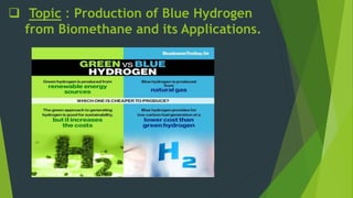
- 4. What is Blue Hydrogen ? Green Hydrogen:- • Produced using Electrolysis. • Reaction : • 2H₂O(l) + 2e⁻ → 2H₂(g) + O₂(g) • No CO2 emitted Blue Hydrogen :- • Produced using Natural gas. • Reaction: • CH₄(g) + H₂O(g) → 3H₂(g) + CO₂(g) • CO2 is captured using CCS tech. Grey Hydrogen:- • Produced using Natural gas. • Reaction: • CH₄(g) + H₂O(g) → 3H₂(g) + CO₂(g) • CO2 is emitted. No CCS is used.
- 5. Methods to produce Blue Hydrogen. Steam Methane Reforming (SMR) with CCS Autothermal Reforming (ATR) with CCS
- 6. A. Steam Methane Reforming (SMR) with CCS :- Reaction CH4 + H2O 3H2 + CO (H)298 = 206 kJ/mol CO + H2O CO2 + H2 (H)298 = - 41.1 kJ/mol {WGS} Parameters Temp. = 700°C – 900°C Press. = 20 – 40 Bar Steam-to-Carbon Ratio (S/C) { 2:3 } Catalysts (Ni, Co, Ru) based catalysts
- 7. Flow Diagram for SMR using CCS :-
- 8. Carbon Capture and Storage (CCS) Methods :- Why important ? M.D.E.A. Methyl Di-ethanol Amine. Advantages : • Selectivity • Versatility • Regenerability • Low Energy Requirements V.P.S.A. Vacuum Pressure Swing Adsorption. Advantages : • Low Operating Costs • Continuous Operation • Adaptability
- 10. Economic Feasibility: Carbon capture, specifically in the context of blue hydrogen production, can increase the cost of hydrogen compared to grey hydrogen due to several factors:
- 11. Challenges :- Carbon Capture and Storage (CCS) Energy Requirements Maintenance Costs CO2 Storage Costs Risk and Uncertainty Initial Capital Investment
- 12. Transportation:- The storage options that are under consideration includes :- Liquid organic hydrogen Pressurized gaseous hydrogen, Cryogenic liquefied hydrogen, Carbonaceous materials hydrogen, Metal alloy hydrogen, Complex hydride hydrogen, Glass microspheres hydrogen,
- 13. Applications :- Blue Hydrogen’s application holds vast potential across diverse sectors, including energy, industry, and transportation, as a crucial step toward a sustainable, low-carbon future.
- 14. Applications: A.) CCS Utilisation :- CCS utilisation has the potential to turn CO2 emissions into valuable resources:
- 15. Extent of CCS utilisation :-