This document provides a summary of commands for the CCNP and CCIE Enterprise Core exams. It begins with copyright information and a warning that no warranty is provided. The book is intended to help with the ENCOR 350-401 and ENARSI 300-410 exams by providing all relevant commands in a portable format.


![xviii Acknowledgments
Finally, to my good friend Scott. Like the first book we worked on together, this one has
been fun and engaging. Thanks for putting up with all those early-morning and late-night
calls as we dealt with the 15-hour time difference between Edmonton and Perth. For the
last time, no, I don’t have the winning lottery ticket numbers even though it’s already
tomorrow in Australia.
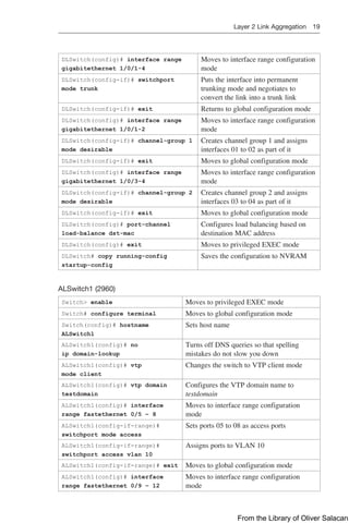
Command Syntax Conventions
The conventions used to present command syntax in this book are the same conventions
used in the IOS Command Reference. The Command Reference describes these conven-
tions as follows:
Q
Q Boldface indicates commands and keywords that are entered literally as shown.
In actual configuration examples and output (not general command syntax),
boldface indicates commands that are manually input by the user (such as a show
command).
Q
Q Italic indicates arguments for which you supply actual values.
Q
Q Vertical bars (|) separate alternative, mutually exclusive elements.
Q
Q Square brackets ([ ]) indicate an optional element.
Q
Q Braces ({ }) indicate a required choice.
Q
Q Braces within brackets ([{ }]) indicate a required choice within an optional
element.
From the Library of Oliver Salacan](https://image.slidesharecdn.com/portablecommandguide-221029235346-67760e11/85/Portable-Command-Guide-pdf-19-320.jpg)

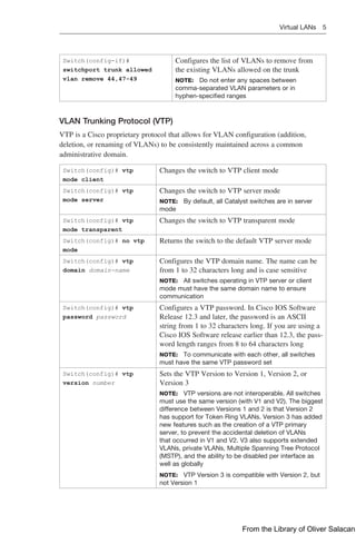
![6 Virtual LANs
Switch# vtp primary
Switch# vtp
primary-server
Changes the operation state of a switch from a second-
ary server (the default state) to a primary server and
advertises the configuration to the domain. If the switch
password is configured as hidden, you are prompted to
reenter the password. This happens only if configured
in Version 2. This prompt occurs in privileged EXEC
mode but not in global configuration mode
NOTE: The vtp primary-server [vlan | mst | force]
commands are only available on older model switches.
On newer switches running more recent IOS/IOS-XE,
use the vtp primary [vlan | mst | force] command
instead
Switch# vtp primary vlan (Optional) Configures the device as the primary VTP
server for VLANs
Switch# vtp primary mst (Optional) Configures the devices as the primary VTP
server for the multiple spanning tree (MST) feature
Switch# vtp primary
force
(Optional) Configures the device to not check for
conflicting devices when configuring the primary
server
Switch(config)# vtp
pruning
Enables VTP pruning
NOTE: By default, VTP pruning is disabled. You need
to enable VTP pruning on only one switch in VTP server
mode
NOTE: Only VLANs included in the pruning-eligible list can be pruned. VLANs 2
through 1001 are pruning eligible by default on trunk ports. Reserved VLANs and
extended-range VLANs cannot be pruned. To change which eligible VLANs can be
pruned, use the interface-specific switchport trunk pruning vlan command:
Switch(config-if)# switchport trunk pruning vlan remove 4,20-30
! Removes VLANs 4 and 20-30
Switch(config-if)# switchport trunk pruning vlan except 40-50
! All VLANs are added to the pruning list except for 40-50
CAUTION: Due to the inherent risk in having VTP servers overwrite each other and
cause VLANs to disappear, Cisco recommends as a best practice deploying VTP in
transparent mode. If you are going to use a client/server model, use Version 3 and the
use of a VTPv3 primary server to prevent accidental database overwrites.
Verifying VTP
Switch# show vtp status Displays general information about VTP configuration
Switch# show vtp
counters
Displays the VTP counters for the switch
Switch# show vtp
password
Displays the VTP passwords
NOTE: If trunking has been established before VTP is set up, VTP information is propa-
gated throughout the switch fabric almost immediately. However, because VTP informa-
tion is advertised only every 300 seconds (5 minutes), unless a change has been made
to force an update, it can take several minutes for VTP information to be propagated.
From the Library of Oliver Salacan](https://image.slidesharecdn.com/portablecommandguide-221029235346-67760e11/85/Portable-Command-Guide-pdf-29-320.jpg)
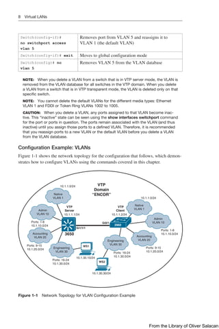
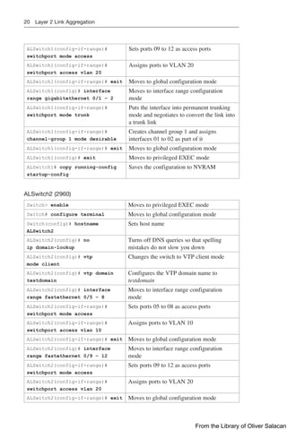
![Virtual LANs 7
Verifying VLAN Information
Switch# show vlan Displays VLAN information
Switch# show vlan brief Displays VLAN information in brief
Switch# show vlan id 2 Displays information of VLAN 2 only
Switch# show vlan name
marketing
Displays information of VLAN named marketing only
Switch# show
interfaces trunk
Displays trunk ports, trunking modes, encapsulation,
and native and allowed VLANs
Switch# show
interfaces switchport
Displays the administrative and operational status of
trunks, encapsulation, private VLAN, voice VLAN,
and trunk VLAN pruning
Switch# show interface
fastethernet 0/1 trunk
Displays the administrative and operational status of a
trunking port
Saving VLAN Configurations
The stored configurations of VLANs 1 through 1005 are always saved in the VLAN
database; the filename is vlan.dat and is stored in flash:. After creating or deleting a
VLAN in VLAN configuration mode, the exit command will apply any new changes to
the VLAN database.
If you are using VTP transparent mode, the configurations are also saved in the
running configuration, and can be saved to the startup configuration using the copy
running-config startup-config command.
If the VTP mode is transparent in the startup configuration, and the VLAN database and
the VTP domain name from the VLAN database matches that in the startup configuration
file, the VLAN database is ignored (cleared), and the VTP and VLAN configurations
in the startup configuration file are used. The VLAN database revision number remains
unchanged in the VLAN database.
Erasing VLAN Configurations
Switch# delete
flash:vlan.dat
Removes entire VLAN database from flash
CAUTION: Make sure that there is no space between
the colon (:) and the characters vlan.dat. You can
potentially erase the entire contents of the flash with this
command if the syntax is not correct. Make sure to read
the output from the switch. If you need to cancel, press
Ctrl+C to escape back to privileged mode:
Switch#
Switch# delete flash:vlan.dat
Delete filename [vlan.dat]?
Delete flash:vlan.dat? [confirm]
Switch#
Switch(config)# interface
fastethernet 0/5
Moves to interface configuration mode
From the Library of Oliver Salacan](https://image.slidesharecdn.com/portablecommandguide-221029235346-67760e11/85/Portable-Command-Guide-pdf-30-320.jpg)
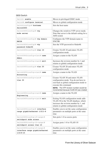

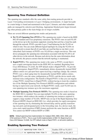
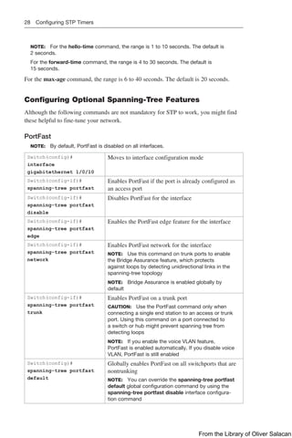
![30 Configuring Optional Spanning-Tree Features
Switch(config)# spanning-tree
portfast bpduguard default
Enables BPDU Guard globally
NOTE: By default, BPDU Guard is disabled
Switch(config)# interface
gigabitethernet 1/0/2
Enters into interface configuration mode
Switch(config-if)# spanning-
tree portfast edge
Enables the PortFast edge feature
Switch(config-if)# end Returns to privileged EXEC mode
BPDU Filter
Switch(config)# spanning-
tree portfast bpdufilter
default
Globally enables BPDU filtering on PortFast-
enabled port; prevents ports in PortFast from
sending or receiving BPDUs
Switch(config)# interface
range gigabitethernet 1/0/1-4
Enters interface range configuration mode
Switch(config-if-range)#
spanning-tree portfast
Enables PortFast on all interfaces in the range
Switch(config-if-range)#
spanning-tree portfast edge
Enables PortFast on all interfaces in the range
NOTE: This is the command for the
3650/9300 series
Switch(config-if-range)#
spanning-tree bpdufilter
enable
Enables BPDU Filter on all interfaces in the
range configured with “PortFast”
NOTE: By default, BPDU filtering is disabled.
Also, BPDU Guard has no effect on an inter-
face if BPDU filtering is enabled
CAUTION: Enabling BPDU filtering on an
interface, or globally, is the same as disabling
STP, which can result in spanning-tree loops
being created but not detected
Switch# show spanning-tree
summary totals
Displays global BPDU filtering configuration
information
Switch# show spanning-tree
interface [interface-type,
interface-number] detail
Displays detailed spanning-tree interface status
and configuration information of the specified
interface
UplinkFast
Switch(config)# spanning-tree
uplinkfast
Enables UplinkFast. UplinkFast provides
fast convergence after a direct link failure
Switch(config)# spanning-tree
uplinkfast max-update-rate 200
Enables UplinkFast and sets the update
packet rate to 200 packets/second
NOTE: UplinkFast cannot be set on
an individual VLAN. The spanning-tree
uplinkfast command affects all VLANs
From the Library of Oliver Salacan](https://image.slidesharecdn.com/portablecommandguide-221029235346-67760e11/85/Portable-Command-Guide-pdf-53-320.jpg)
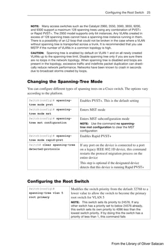
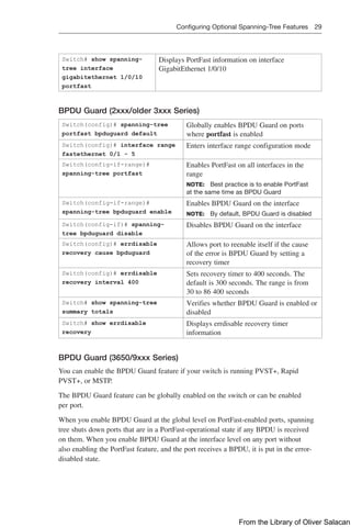
![Configuring and Verifying Port Error Conditions 33
Switch# show spanning-tree
summary
Verifies whether Loop Guard has been
enabled
Switch# show spanning-tree
interface detail
Display spanning-tree link type. A link type
of “point to point” is required for Loop
Guard
Unidirectional Link Detection
Switch(config)# udld
enable
Enables unidirectional link detection (UDLD) on all
fiber-optic interfaces to determine the Layer 1 status
of the link
NOTE: By default, UDLD is disabled
Switch(config)# udld
aggressive
Enables UDLD aggressive mode on all fiber-optic
interfaces
Switch(config)# interface
gigabitethernet 1/0/1
Moves to interface configuration mode
Switch(config-if)# udld
port
[aggressive]
Enables UDLD on this interface (required for copper-
based interfaces) in normal or aggressive mode
NOTE: On a fiber-optic (FO) interface, the interface
command udld port overrides the global command
udld enable. Therefore, if you issue the command
no udld port on an FO interface, you will still have
the globally enabled udld enable command to
deal with
Switch# show udld Displays UDLD information
Switch# show udld
interface
gigabitethernet 1/0/1
Displays UDLD information for interface Gigabit
Ethernet 1/0/1
Switch# udld reset Resets all interfaces shut down by UDLD
NOTE: You can also use the shutdown command,
followed by a no shutdown command in interface
configuration mode, to restart a disabled interface
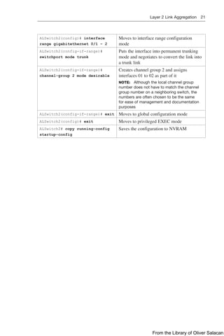
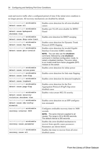
Configuring and Verifying Port Error Conditions
A port is “error-disabled” when the switch detects any one of a number of port viola-
tions. No traffic is sent or received when the port is in error-disabled state. The show
errdisable detect command displays a list for the possible error-disabled reasons and
whether enabled.
The errdisable detect cause command allows the network device administrator to enable or
disable detection of individual error-disabled causes. All causes are enabled by default. All
causes, except for per-VLAN error disabling, are configured to shut down the entire port.
The errdisable recovery command enables the network device administrator to config-
ure automatic recovery mechanism variables. This would allow the switch port to again
From the Library of Oliver Salacan](https://image.slidesharecdn.com/portablecommandguide-221029235346-67760e11/85/Portable-Command-Guide-pdf-56-320.jpg)

![68 Authentication for EIGRP
Router(config-keychain-
key)# accept-lifetime
[local] start-time
{infinite | end-time |
duration seconds}
(Optional) Specifies the period during which the key
can be received
local keyword specifies time in local time zone
NOTE: After the time is entered, you have the
option to add the specific day/month/year to this
command
NOTE: The default start time and the earliest
acceptable date is January 1, 1993. The default end
time is an infinite time period
Router(config-keychain-
key)# send-lifetime
[local] start-time
{infinite | end-time |
duration seconds}
(Optional) Specifies the period during which the key
can be sent
local keyword specifies time in local time zone
NOTE: After the time is entered, you have the
option to add the specific day/month/year to this
command
NOTE: The default start time and the earliest
acceptable date is January 1, 1993. The default end
time is an infinite period
Router(config)#
interface
gigabitethernet 0/0/0
Enters interface configuration mode
Router(config-if)#
ip authentication mode
eigrp 100 md5
Enables message digest 5 (MD5) authentication in
EIGRP packets over the interface
Router(config-if)# ip
authentication key-chain
eigrp 100 romeo
Enables authentication of EIGRP packets using
romeo as the key chain
Router(config-if)# exit Returns to global configuration mode
NOTE: For the start time and the end time to have relevance, ensure that the router
knows the correct time. Recommended practice dictates that you run NTP or some
other time-synchronization method if you intend to set lifetimes on keys.
Configuring Authentication in Named Mode
NOTE: EIGRP support for SHA was introduced in Cisco IOS 15 together with EIGRP
using named mode configuration.
NOTE: Both MD5 and SHA can be used in either IPv4 or IPv6. Not all permutations
are shown in the following example.
Router(config)# router eigrp
TEST
Creates a named EIGRP virtual instance called
TEST
Router(config-router)#
address-family ipv4
autonomous-system 1
Enables the IPv4 address family and starts
EIGRP AS 1
Router(config-router-af)#
af-interface
gigabitethernet 0/0/0
Moves the router into address family inter-
face
configuration mode for interface
GigabitEthernet 0/0/0
From the Library of Oliver Salacan](https://image.slidesharecdn.com/portablecommandguide-221029235346-67760e11/85/Portable-Command-Guide-pdf-91-320.jpg)


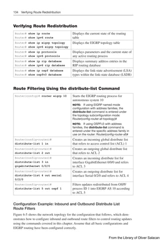
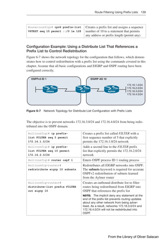
![Route Filtering Using Prefix Lists 137
NOTE: For each interface and routing process, Cisco IOS permits the following:
Q
Q One incoming global distribute list
Q
Q One outgoing global distribute list
Q
Q One incoming interface distribute list
Q
Q One outgoing interface distribute list
Q
Q One outgoing redistribution distribute list
CAUTION: For OSPF, route filters have no effect on LSAs or the LSDB. A basic
requirement of link-state routing protocols is that routers in an area must have identical
LSDBs.
NOTE: OSPF routes cannot be filtered from entering the OSPF database. The
distribute-list in command filters routes only from entering the routing table, but it
doesn’t prevent link-state packets (LSPs) from being propagated.
NOTE: The command distribute-list out works only on the routes being redistributed
by the ASBR into OSPF. It can be applied to external type-2 and external type-1 routes
but not to intra-area and interarea routes.
Route Filtering Using Prefix Lists
The general syntax for configuring IPv4 and IPv6 prefix lists is as follows:
Router(config)# ip prefix-list list-name [seq seq-value]
{deny | permit} network/len [ge ge-value] [le le-value]
Router(config)# ipv6 prefix-list list-name [seq seq-value]
{deny | permit} network/len [ge ge-value] [le le-value]
The table that follows describes the parameters for this command.
Parameter Description
list-name The name of the prefix list
seq (Optional) Applies a sequence number to the entry being created or
deleted
seq-value (Optional) Specifies the sequence number
deny Denies access to matching conditions
permit Permits access for matching conditions
network/len (Mandatory) The IPv4 or IPv6 network number and length (in bits) of
the netmask
ge (Optional) Applies ge-value to the range specified
ge-value (Optional) Specifies the lesser value of a range (the “from” portion of
the range description)
le (Optional) Applies le-value to the range specified
le-value (Optional) Specifies the greater value of a range (the “to” portion of
the range description)
TIP: You must define a prefix list before you can apply it as a route filter.
TIP: There is an implicit deny statement at the end of each prefix list.
From the Library of Oliver Salacan](https://image.slidesharecdn.com/portablecommandguide-221029235346-67760e11/85/Portable-Command-Guide-pdf-160-320.jpg)
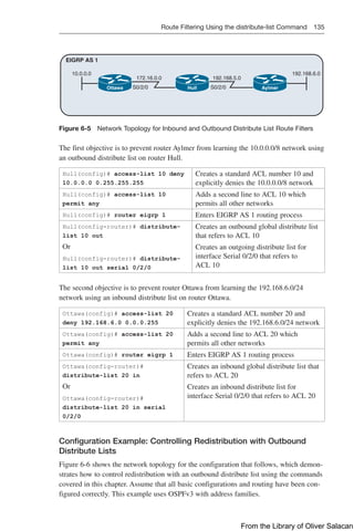
![140 Route Filtering Using Prefix Lists
TIP: You can attach prefix lists to the redistribution process either via a distribute list
or via a route map.
Verifying Prefix Lists
show ip prefix-list [detail |
summary]
show ipv6 prefix-list [detail |
summary]
Displays information on all prefix lists.
Specifying the detail keyword includes the
description and the hit count (the number
of times the entry matches a route) in the
display
clear ip prefix-list prefix-
list-name [network/length]
clear ipv6 prefix-list prefix-
list-name [network/length]
Resets the hit count shown on prefix list
entries
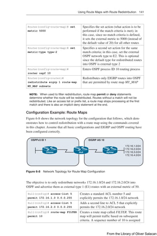
Using Route Maps with Route Redistribution
Router(config)# route-map MY_
MAP permit 10
Creates a route map called MY_MAP. This
route-map statement will be used to permit
redistribution based on subsequent criteria.
A sequence number of 10 is assigned
Router(config-route-map)# match
ip address 5
Specifies the match criteria (the conditions
that should be tested); in this case, match
addresses filtered using a standard access list
number 5
Router(config-route-map)# set
metric 500
Specifies the set action (what action is to
be performed if the match criteria is met);
in this case, set the external metric to 500
(instead of the default value of 20 for OSPF)
Router(config-route-map)# set
metric-type type-1
Specifies a second set action for the same
match criteria. In this case, set the external
OSPF network type to E1
Router(config-route-map)#
route-map MY_MAP deny 20
Adds a second statement to the MY_MAP
route map that will deny redistribution based
on subsequent criteria
Router(config-route-map)# match
ip address prefix-list MY_PFL
Specifies the match criteria (the conditions
that should be tested); in this case, match
addresses filtered using a prefix list named
MY_PFL
Router(config-route-map)#
route-map MY_MAP permit 30
Adds a third statement to the MY_MAP route
map that will permit redistribution based on
subsequent criteria
NOTE: When no “match” criteria are explicitly
specified, all other routes will be redistributed
with the following “set” criteria applied
From the Library of Oliver Salacan](https://image.slidesharecdn.com/portablecommandguide-221029235346-67760e11/85/Portable-Command-Guide-pdf-163-320.jpg)
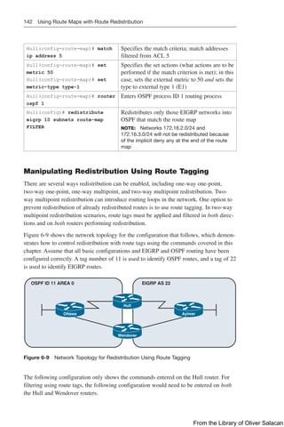
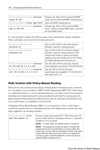
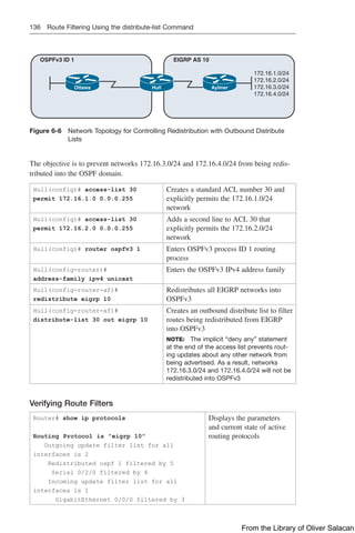
![Verifying Policy-Based Routing 145
Router(config-route-
map)# match ip
address 1
Specifies the match criteria (the conditions that should
be tested); in this case, match addresses using ACL 1
Router(config-route-
map)# set ip next-hop
209.165.201.1
Specifies the set action (what action is to be performed
if the match criteria are met); in this case, output
packets to the router at IP address 209.165.201.1
Router(config-route-
map)# set interface
serial 0/2/0
Specifies the set action (what action is to be performed
if the match criteria are met); in this case, forward
packets out interface Serial 0/2/0
NOTE: If no explicit route exists in the routing table
for the destination network address of the packet (that
is, the packet is a broadcast packet or destined to an
unknown address), the set interface command has no
effect and is ignored
NOTE: A default route in the routing table will not be
considered an explicit route for an unknown destination
address
Router(config-route-
map)# set ip default
next-hop 209.165.201.1
Defines where to output packets that pass a match
clause of a route map for policy routing and for which
the router has no explicit route to the destination address
Router(config-route-
map)# set default
interface serial 0/2/0
Defines where to output packets that pass a match
clause of a route map for policy routing and for which
the router has no explicit route to the destination address
NOTE: This is recommended for point-to-point links only
Router(config-route-
map)# exit
Returns to global configuration mode
Router(config)#
interface
gigabitethernet 0/0/0
Moves to interface configuration mode
Router(config-if)# ip
policy route-map ISP1
Specifies a route map to use for policy routing on an
incoming interface that is receiving the packets that
need to be policy routed
Router(config-if)# exit Returns to global configuration mode
Router(config)# ip
local policy route-map
ISP1
Specifies a route map to use for policy routing on all
packets originating on the router
TIP: Packets that are generated by the router are not normally policy routed. Using
the ip local policy route-map [map-name] command will make these packets adhere
to a policy. For example, you may want packets originating from the router to take a
route other than the best path according to the routing table.
Verifying Policy-Based Routing
Router# show ip policy Displays route maps that are configured on the
interfaces
Router# show route-map
[map-name]
Displays route maps
From the Library of Oliver Salacan](https://image.slidesharecdn.com/portablecommandguide-221029235346-67760e11/85/Portable-Command-Guide-pdf-168-320.jpg)
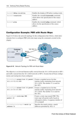
![Cisco IOS IP SLA 149
DLS1(config-ip-sla-echo)#
frequency 5
Sets the rate at which the IP SLA operation
repeats. Frequency is measured in seconds.
The default value is 60 seconds
DLS1(config-ip-sla-echo)# exit Exits IP SLA configuration mode
DLS1(config)# ip sla schedule
11 start-time now life forever
Configures the IP SLA operation scheduling
parameters to start now and continue forever
NOTE: The start time for the SLA can be set to
a particular time and day, to be recurring, to be
activated after a threshold is passed, and kept
as an active process for a configurable number
of seconds
DLS2(config)# ip sla responder Enables IP SLA responder functionality in
response to control messages from the source.
This command is entered on the target device
DLS1(config)# ip sla 12 Creates an IP SLA operation and enters IP
SLA configuration mode
DLS1(config-ip-sla)# path-
jitter 172.19.1.2 source-ip
10.1.1.1 [targetOnly]
Configures the IP SLA as an ICMP path-jitter
operation and enters path-jitter configuration
mode. ICMP path jitter provides hop-by-hop
jitter, packet loss, and delay measurement
statistics in an IP network. Adding the
targetOnly keyword bypasses the hop-by-hop
measurements and echo probes are sent to the
destination only
NOTE: The ICMP path-jitter SLA sends 10
packets per operation with a 20-ms time inter-
val between them by default. These values are
configurable
DLS1(config-ip-sla-path-
jitter)# frequency 5
Sets the rate at which the IP SLA operation
repeats. The default value is 60 seconds
DLS1(config-ip-sla-path-
jitter)# exit
Exits path-jitter configuration mode
DLS1(config)# ip sla schedule
12 recurring start-time 07:00
life 3600
Configures the IP SLA operation scheduling
parameters to start at 7 a.m. and continue for
1 hour every day. 3600 seconds is the default
life time for an IP SLA. The switch will
require accurate time and date to implement
the SLA schedule
TIP: When using udp-echo, udp-jitter, or tcp-connect IP SLA operations, you must
configure the target device as an IP SLA responder with either the udp-echo or tcp-
connect commands.
Configuring Authentication for IP SLA
Router(config)# key chain Juliet Identifies a key chain
Router(config-keychain)# key 1 Identifies the key number
Router(config-keychain)#
key-string Shakespeare
Identifies the key string
From the Library of Oliver Salacan](https://image.slidesharecdn.com/portablecommandguide-221029235346-67760e11/85/Portable-Command-Guide-pdf-172-320.jpg)


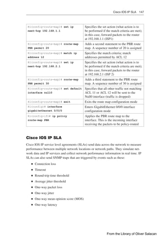
![176 Troubleshooting BGP
Router# clear ip bgp {* |
10.1.1.2} [soft in | in]
Creates a dynamic soft reset of inbound
BGP routing table updates. Routes are not
withdrawn. Updates are not stored locally.
The connection remains established. See
the notes that follow for more information
on when this command can be used
Router# debug ip bgp Displays all information related to BGP
Router# debug ip bgp events Displays all BGP event information
Router# debug ip bgp updates Displays information about the processing
of BGP update
Router# debug ip bgp ipv4 unicast Displays all IPv4 unicast address family
information
Router# debug ip bgp ipv6 unicast Displays all IPv6 unicast address family
information
NOTE: Beginning with Cisco IOS Releases 12.0(2)S and 12.0(6)T, Cisco introduced
a BGP soft reset enhancement feature known as route refresh. Route refresh is not
dependent on stored routing table update information. This method requires no pre-
configuration and requires less memory than previous soft methods for inbound routing
table updates.
NOTE: To determine whether a BGP router supports route refresh capability, use the
show ip bgp neighbors command. The following message is displayed in the output
when route refresh is supported:
Received route refresh capability from peer
NOTE: When a BGP session is reset and soft reconfiguration is used, several com-
mands enable you to monitor BGP routes that are received, sent, or filtered:
Router# show ip bgp
Router# show ip bgp neighbor address advertised
Router# show ip bgp neighbor address received
Router# show ip bgp neighbor address routes
CAUTION: The clear ip bgp * command is both processor and memory intensive and
should be used only in smaller environments. A more reasonable approach is to clear
only a specific network or a specific session with a neighbor with the clear ip bgp
specific-network command. However, you can use this command whenever the follow-
ing changes occur:
Q
Q Additions or changes to the BGP-related access lists
Q
Q Changes to BGP-related weights
Q
Q Changes to BGP-related distribution lists
Q
Q Changes in the BGP timer’s specifications
Q
Q Changes to the BGP administrative distance
Q
Q Changes to BGP-related route maps
From the Library of Oliver Salacan](https://image.slidesharecdn.com/portablecommandguide-221029235346-67760e11/85/Portable-Command-Guide-pdf-199-320.jpg)
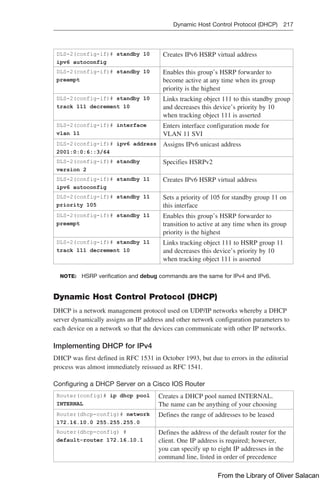
![224 Dynamic Host Control Protocol (DHCP)
Verifying and Troubleshooting DHCPv6
Router# show ipv6 dhcp binding Displays the IPv6 to MAC address bindings
Router# show ipv6 dhcp pool Displays DHCPv6 pool statistics
Router# show ipv6 dhcp
interface
Displays interface on which DHCPv6 is
enabled
Router# debug ipv6 dhcp
[detail]
Enables DHCPv6 debugging
Router# debug ipv6 dhcp relay Enables DHCPv6 relay agent debugging
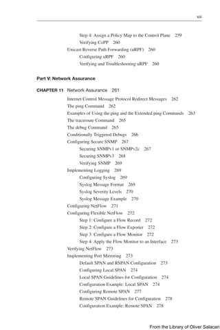
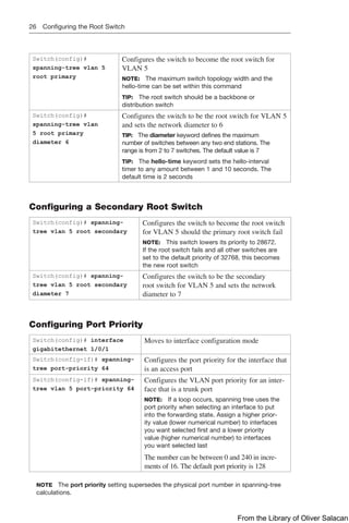
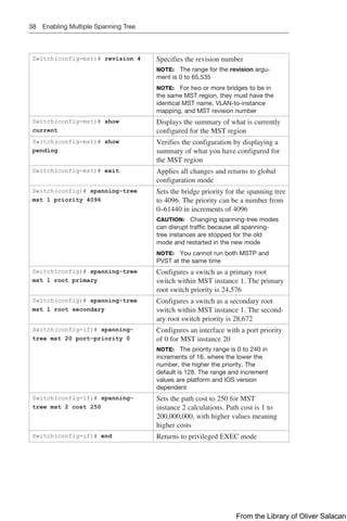
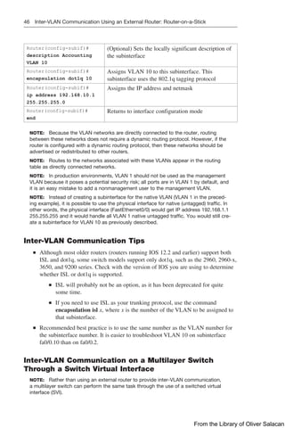
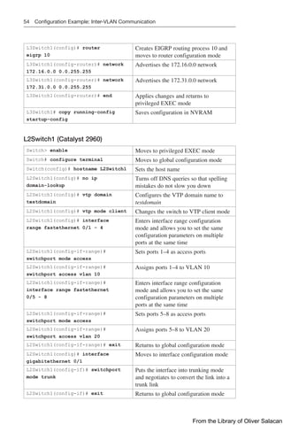
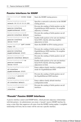
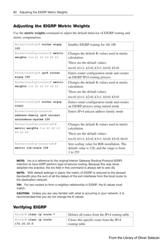
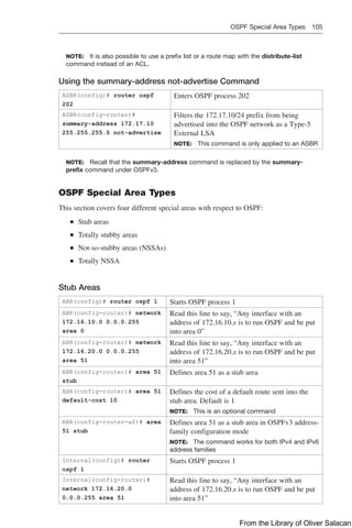
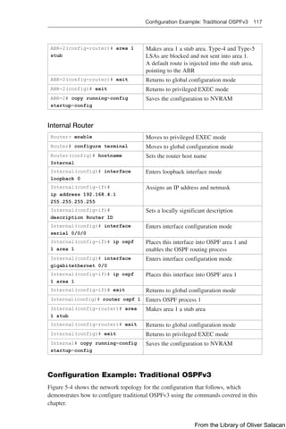
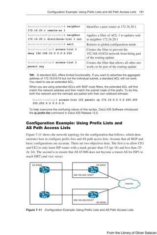
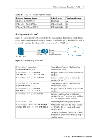
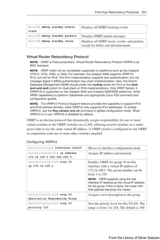
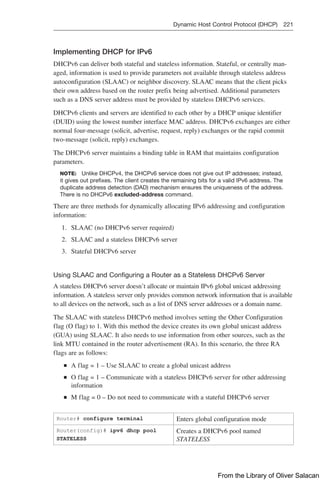
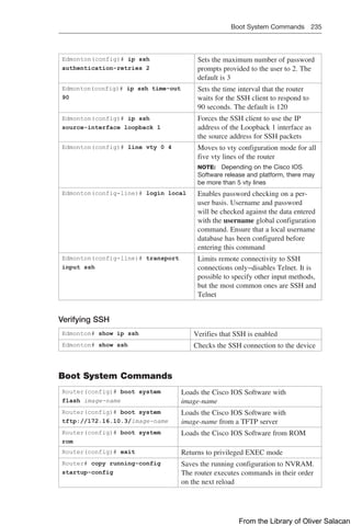
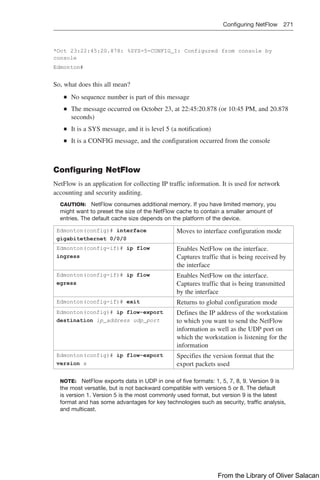
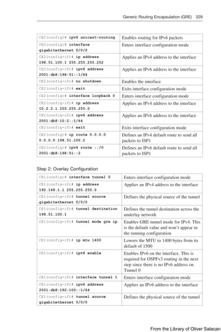
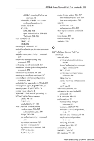
Configuration Example: DHCP for IPv4
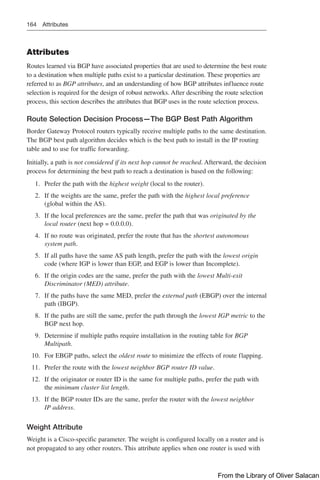
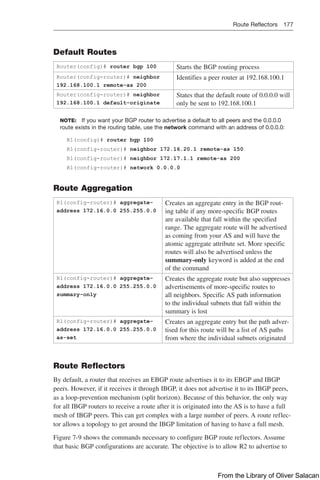
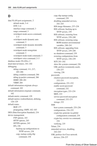
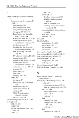
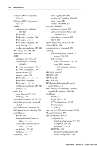
Figure 8-11 illustrates the network topology for the configuration that follows, which
shows how to configure DHCP services on a Cisco IOS router using the commands
covered in this chapter.
NetBIOS Server
10.0.0.2/8
DNS Server
10.0.0.3/8
Edmonton
is an IOS
DHCP
Server
Network 10.0.0.0/8 Network 192.168.1.0/30 Network 192.168.3.0/24
Gi0/0
10.0.0.1/24
S0/0/0
192.168.1.2/30 Gi0/0
192.168.3.1/24
192.168.1.1/30
DCE
DHCP Client
DHCP Client
S0/0/1
Edmonton
Gibbons
Figure 8-11 Network Topology for DHCP Configuration
Edmonton Router
Router enable Moves to privileged EXEC mode
Router# configure terminal Moves to global configuration mode
Router(config)# hostname Edmonton Sets the host name
Edmonton(config)# interface
gigabitethernet 0/0
Moves to interface configuration mode
Edmonton(config-if)# description
LAN Interface
Sets the local description of the interface
Edmonton(config-if)# ip address
10.0.0.1 255.0.0.0
Assigns an IP address and netmask
Edmonton(config-if)# no shutdown Enables the interface
Edmonton(config-if)# interface
serial 0/0/0
Moves to interface configuration mode
Edmonton(config-if)# description
Link to Gibbons Router
Sets the local description of the interface
From the Library of Oliver Salacan](https://image.slidesharecdn.com/portablecommandguide-221029235346-67760e11/85/Portable-Command-Guide-pdf-247-320.jpg)

![238 Deciphering IOS Image Filenames
16.09.04 Identifies the version number of the software. In this case, it is major
release 16, minor release 9, new feature release 4
SPA Indicates this software is digitally signed. There are two file extensions
possible: SPA and SSA. The first character S stands for digitally signed
software. The second character P in SPA means that this release is
meant for production. A second character S in SSA means it is a special
image and has limited use or special conditions. The third character
A indicates the key version used to digitally sign the image
.bin Represents the file extension. .bin shows that this file is a binary
executable file
NOTE: The Cisco IOS naming conventions, meanings, content, and other details are
subject to change.
Backing Up Configurations to a TFTP Server
Denver# copy running-config
startup-config
Saves the running configuration from
DRAM to NVRAM (locally)
Denver# copy running-config tftp Copies the running configuration to the
remote TFTP server
Address or name of remote
host[ ]? 192.168.119.20
The IP address of the TFTP server
Destination Filename
[Denver-confg]?
The name to use for the file saved on the
TFTP server
!!!!!!!!!!!!!!! Each bang symbol (!) = 1 datagram of data
624 bytes copied in 7.05 secs
Denver# File has been transferred successfully
NOTE: You can also use the preceding sequence for a copy startup-config tftp
command sequence.
Restoring Configurations from a TFTP Server
Denver# copy tftp running-config Merges the configuration file from
the TFTP server with the running-
config file in DRAM
Address or name of remote host[ ]?
192.168.119.20
The IP address of the TFTP server
Source filename [ ]? Denver-confg Enter the name of the file you want
to retrieve
Destination filename [running-
config]?
Pressing the Enter key will begin the
copy process
Accessing tftp://192.168.119.20/
Denver-confg...
From the Library of Oliver Salacan](https://image.slidesharecdn.com/portablecommandguide-221029235346-67760e11/85/Portable-Command-Guide-pdf-261-320.jpg)
![Restoring/Upgrading the Cisco IOS Software from a TFTP Server 239
Loading Denver-confg from
192.168.119.02 (via GigabitEthernet
0/0):
!!!!!!!!!!!!!!
[OK-624 bytes]
624 bytes copied in 9.45 secs
Denver# File has been transferred successfully
NOTE: You can also use the preceding sequence for a copy tftp startup-config
command sequence.
NOTE: When copying a file into a configuration file, the no shutdown command does
not carry over into the configuration file. You must enable the interfaces with the no
shutdown command.
Backing Up the Cisco IOS Software to a TFTP Server
Denver# copy flash: tftp: Copies from flash to a remote
TFTP server
Source filename [ ]? isr4300-
universalk9.16.09.04.SPA.bin
Name of the Cisco IOS Software
image
Address or name of remote host [ ]?
192.168.119.20
Address of the TFTP server
Destination filename [isr4300-
universalk9.16.09.04.SPA.bin]?
The destination filename is the same
as the source filename, so just press
!!!!!!!!!!!!!!!!!!!!!!!!!!!!!!!!!!!!!!
!!!!!!!!!!!!!!!!!!!!!!!!!!!!!!!!!!!!!!
!!!!!!!!
8906589 bytes copied in 263.68 seconds
Denver#
Restoring/Upgrading the Cisco IOS Software
from a TFTP Server
Denver# copy tftp: flash: Copies from a remote TFTP server
to flash
Address or name of remote host [ ]?
192.168.119.20
Source filename [ ]? isr4300-
universalk9.16.09.04.SPA.bin
Destination filename [isr4300-
universalk9.16.09.04.SPA.bin]?
From the Library of Oliver Salacan](https://image.slidesharecdn.com/portablecommandguide-221029235346-67760e11/85/Portable-Command-Guide-pdf-262-320.jpg)
![240 Restoring/Upgrading the Cisco IOS Software from a TFTP Server
Accessing tftp://192.168.119.20/
isr4300-universalk9.16.09.04.SPA.bin
Erase flash: before copying?
[confirm]
If flash memory is full, erase it first
Erasing the flash file system will
remove all files
Continue? [confirm] Press Ctrl-C if you want to cancel
Erasing device eeeeeeeeeeeeeeeeee...
erased
Each e represents data being erased
Loading isr4300-universalk9.16.09.04.
SPA.bin from 192.168.119.20
(via GigabitEthernet 0/0): !!!!!!!!!
!!!!!!!!!!!!!!!!!!!!!!!!!!!!!!!!!!!!
!!!!!!!!!!!!!!!!!!!!!!!!!!!!!!!!!!!!
!!!!!!!!!!
Each bang symbol (!) = 1 datagram
of data
Verifying Check sum
.................. OK
[OK - 8906589 Bytes]
8906589 bytes copied in 277.45 secs
Denver# Success
Restoring the Cisco IOS Software Using the ROM
Monitor Environmental Variables and tftpdnld Command
rommon 1 IP_
ADDRESS=192.168.100.1
Indicates the IP address for this unit
rommon 2 IP_SUBNET_
MASK=255.255.255.0
Indicates the subnet mask for this unit
rommon 3 DEFAULT_
GATEWAY=192.168.100.1
Indicates the default gateway for this unit
rommon 4 TFTP_
SERVER=192.168.100.2
Indicates the IP address of the TFTP server
rommon 5 TFTP_FILE=
c2900-universalk9-mz.SPA.
152-4.M1.bin
Indicates the filename to fetch from the TFTP
server
rommon 6 tftpdnld Starts the process
...output cut...
Do you wish to continue? y/n:
[n]:y
...output cut...
rommon 7 i Resets the router. The i stands for initialize
From the Library of Oliver Salacan](https://image.slidesharecdn.com/portablecommandguide-221029235346-67760e11/85/Portable-Command-Guide-pdf-263-320.jpg)
![242 Secure Copy Protocol (SCP)
NOTE: Your router does not need to be set up as an SCP server for this transfer to
work. You only need to have SSH configured.
Denver# copy flash: scp: Initiates secure copy from flash: to
a remote host
Source filename []? isr4300-
universalk9.16.09.04.SPA.bin
Enter the name of the file you want
to transfer
Address or name of remote host[]?
192.168.119.20
The IP address of the remote host
Destination username [Denver]?
superuser
The username needed for the
connection
Destination filename [isr4300-
universalk9.16.09.04.SPA.bin]?
Press Enter, as the filename is
already prompted
Writing isr4300-
universalk9.16.09.04.SPA.bin
Connection is being created and
verified
Password: Enter the password when prompted
!!!!!!!!!!!!!!!!!!!!!!!!!!!!!!!!!!!!!
!!!!!!
Each bang symbol (!) = 1 datagram
of data
Denver# File has been transferred
successfully
NOTE: As with any use of the copy command, you can enter some of the specific
details into the command itself:
Denver# copy flash:isr4300-universalk9.16.09.04.SPA.bin
scp://superuser@192.168.119.20/
Disabling Unneeded Services
Services that are not being used on a router can represent a potential security risk. If you
do not need a specific service, you should disable it.
TIP: If a service is off by default, disabling it does not appear in the running
configuration.
TIP: Do not assume that a service is disabled by default; you should explicitly disable
all unneeded services, even if you think they are already disabled.
TIP: Depending on the Cisco IOS Software release, some services are on by default;
some are off. Be sure to check the IOS configuration guide for your specific software
release to determine the default state of the service.
Table 9-2 lists the services that you should disable if you are not using them.
From the Library of Oliver Salacan](https://image.slidesharecdn.com/portablecommandguide-221029235346-67760e11/85/Portable-Command-Guide-pdf-265-320.jpg)

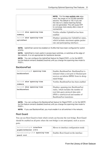
![Implementing Authentication Methods 255
form. Although IOS will still accept plaintext passwords entered at the CLI, it will not
store them as plaintext in the configuration. To enable strong password encryption
using AES, you need to enter two commands. The first, key config-key password-
encryption [master key], allows you to configure a master key that will be used to
encrypt all other keys in the router configuration. The master key is not stored in the
router configuration and cannot be seen or obtained in any way while connected to the
router. The second command, password encryption aes, triggers the actual password
encryption process.
For more on this security feature, see “Encrypt Pre-shared Keys in Cisco IOS Router
Configuration Example” at https://www.cisco.com/c/en/us/support/docs/security-vpn/
ipsec-negotiation-ike-protocols/46420-pre-sh-keys-ios-rtr-cfg.html.
TACACS+ Authentication
TACACS+ is a Cisco proprietary protocol that is not compatible with the older ver-
sions such as TACACS or XTACACS, which are now deprecated. TACACS+ allows for
greater modularity, by total separation of all three AAA functions. TACACS+ uses TCP
port 49, and thus reliability is ensured by the transport protocol itself. Entire TACACS+
packets are encrypted, so communication between Network Access Server (NAS) and
the TACACS+ server is completely secure.
Legacy Configuration for TACACS+ Servers
The traditional approach to configure a TACACS+ server on a Cisco IOS device would
be with the tacacs-server global configuration command.
Router(config)# username
admin secret cisco
Creates user with username admin and encrypted
password cisco
Router(config)# aaa
new-model
Enables AAA access control mode
Router(config)# tacacs-
server host 192.168.55.13
single-connection key C1sc0
Specifies a TACACS+ server at 192.168.55.13
with an encryption key of C1sc0. The single-
connection keyword maintains a single open TCP
connection between the switch and the server
Router(config)# aaa
authentication login TACSRV
group tacacs+ local
Sets login authentication for the TACSRV
method list to authenticate to the TACACS+
server first, and the locally defined username and
password second
Router(config)# line
console 0
Moves to console 0 configuration mode
Router(config-line)# login
authentication TACSRV
Specifies the AAA service to use the TACSRV
authentication method list when users connect to
the console port
Modular Configuration for TACACS+ Servers
Similar to the RADIUS modular configuration shown in the previous section, it is
possible to use a modular approach when configuring TACACS+. The same three steps
apply (define TACACS+ server parameters, define TACACS+ server group, and define
AAA commands).
From the Library of Oliver Salacan](https://image.slidesharecdn.com/portablecommandguide-221029235346-67760e11/85/Portable-Command-Guide-pdf-278-320.jpg)
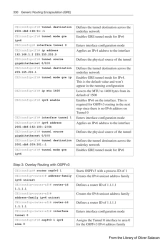
![Examples of Using the ping and the Extended ping Commands 263
Table 11-1 describes the possible ping output characters.
TABLE 11-1 ping Output Characters
Character Description
! Each exclamation point indicates receipt of a reply
. Each period indicates that the network server timed out while wait-
ing for a reply
? Unknown error
@ Unreachable for unknown reason
A Administratively unreachable. Usually means that an access con-
trol list (ACL) is blocking traffic
B Packet too big
H Host unreachable
N Network unreachable (beyond scope)
P Port unreachable
R Parameter problem
T Time exceeded
U No route to host
Examples of Using the ping and the Extended ping
Commands
Router# ping 172.16.20.1 Performs a basic Layer 3 test to IPv4 address
172.16.20.1
Router# ping paris Same as above but through the IP host name
Router# ping
2001:db8:d1a5:c900::2
Checks for Layer 3 connectivity with the device
at IPv6 address 2001:db8:d1a5:c900::2
Router# ping Enters extended ping mode; can now change
parameters of ping test
Protocol [ip]: Press to use ping for IP
Target IP address:
172.16.20.1
Enter the target IP address
Repeat count [5]: 100 Enter the number of echo requests you want to
send. The default is 5
Datagram size [100]: Enter the size of datagrams being sent. The
default is 100
Timeout in seconds [2]: Enter the timeout delay between sending echo
requests
Extended commands [n]: yes Allows you to configure extended commands
From the Library of Oliver Salacan](https://image.slidesharecdn.com/portablecommandguide-221029235346-67760e11/85/Portable-Command-Guide-pdf-286-320.jpg)
![264 Examples of Using the ping and the Extended ping Commands
Source address or interface:
10.0.10.1
Allows you to explicitly set where the pings are
originating from. An interface name may also be
used here
Type of Service [0] Allows you to set the TOS field in the IP header
Set DF bit in IP header [no] Allows you to set the DF bit in the IP header
Validate reply data? [no] Allows you to set whether you want validation
Data Pattern [0xABCD] Allows you to change the data pattern in the
data field of the ICMP echo request packet
Loose, Strict, Record,
Timestamp, Verbose[none]:
Offers IP header options. This prompt offers
more than one of the following options to be
selected:
Verbose is automatically selected along with
any other option
Record is a very useful option because it dis-
plays the address(es) of the hops (up to nine) the
packet goes through
Loose allows you to influence the path by speci-
fying the address(es) of the hop(s) you want the
packet to go through
Strict is used to specify the hop(s) that you want
the packet to go through, but no other hop(s) are
allowed to be visited
Timestamp is used to measure roundtrip time to
particular hosts
Sweep range of sizes [no]: Allows you to vary the sizes of the echo packets
that are sent
Type escape sequence to
abort
Sending 100, 100-byte ICMP
Echos to 172.16.20.1,
timeout is 2 seconds:
Packet sent with a source
address of 10.0.10.1
!!!!!!!!!!!!!!!!!!!!!!!!!!!
!!!!!!!!!!!!!!!!!!!!!!!!!!!
!!!!!!!!!!!!!!!!!!!!!!!!!!!
!!!!!!!!!!!!!!!!!!!!!!!!!!!
!!!!!!!!!!!!!!
Success rate is 100 percent
(100/100) round-trip min/
avg/max = 1/1/4 ms
TIP: If you want to interrupt the ping operation, use the Ctrl-Shift-6 keystroke combi-
nation. This ends the operation and returns you to the prompt.
From the Library of Oliver Salacan](https://image.slidesharecdn.com/portablecommandguide-221029235346-67760e11/85/Portable-Command-Guide-pdf-287-320.jpg)
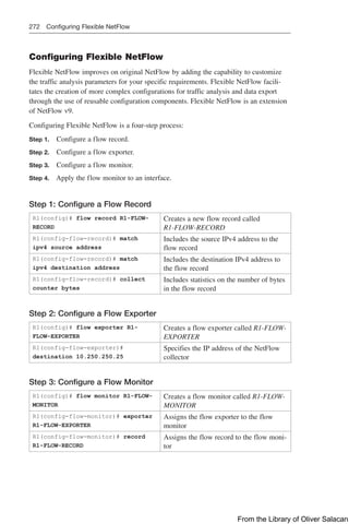
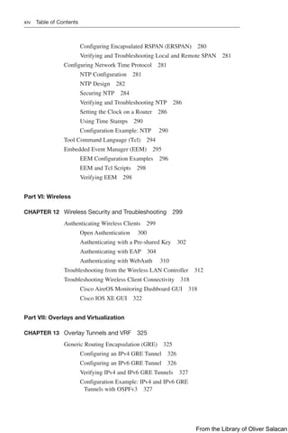
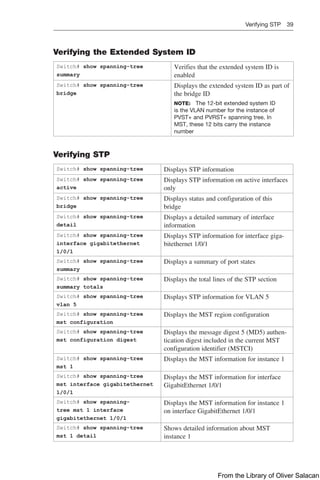
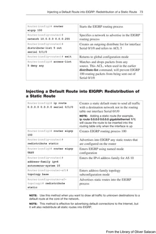
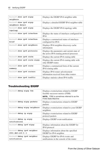
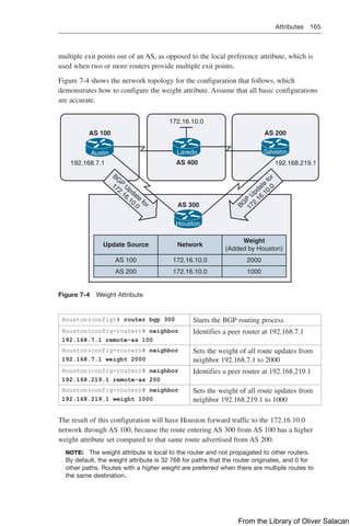
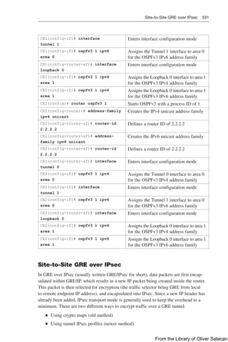
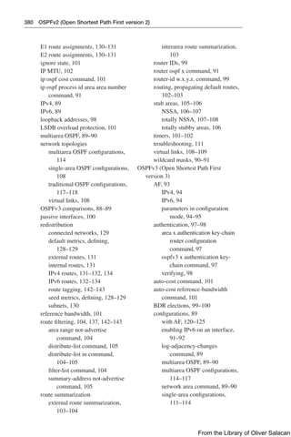
![Implementing Port Mirroring 275
Original traffic
Gi0/1 Gi0/2
Gi0/24
Copy of traffic
WS1 WS2
Sniffer
Switch
Figure 11-1 Local SPAN
Switch(config)# no monitor
session 1
Removes any existing SPAN configura-
tion on session 1. The session number is a
number between 1 and 66
Switch(config)# no monitor
session all
Removes all SPAN sessions
Switch(config)# no monitor
session local
Removes all local SPAN sessions
Switch(config)# no monitor
session remote
Removes all remote SPAN sessions
Switch(config)# monitor
session 1 source interface
gigabitethernet 0/1
Sets a new SPAN session where the
source of the traffic will be interface
GigabitEthernet 0/1
Switch(config)# monitor session 2
source gigabitethernet 0/2 rx
Configures session 2 to monitor received
traffic on interface GigabitEthernet 0/2
Switch(config)# monitor session
session_number source {interface
interface-id | vlan vlan-id} [, |
-] [both | rx | tx]
Options for this command include the fol-
lowing:
session_number: Any number between 1
and 66
interface-id: Specifies the source port to
monitor. Can be any valid physical inter-
face or port channel logical interface
vlan-id: Specifies the source VLAN to
monitor. The range is 1 to 4094
From the Library of Oliver Salacan](https://image.slidesharecdn.com/portablecommandguide-221029235346-67760e11/85/Portable-Command-Guide-pdf-298-320.jpg)
![276 Implementing Port Mirroring
, | - (optional): To be used to help specify
a series or ranges of interfaces. There
must be a space both before and after the
comma or hyphen
both (optional): Monitors both received
and sent traffic. This is the default setting
rx (optional): Monitors received traffic
tx (optional): Monitors sent traffic
NOTE: A single session can include
multiple sources (ports or VLANs),
defined in a series of commands, but you
cannot combine source ports and source
VLANs in one session
NOTE: You can use the monitor session
session_number source command multi-
ple times to configure multiple source ports
Switch(config)# monitor session 1
filter vlan 6 - 10
Limits the SPAN source traffic to VLANs
6 to 10
Switch(config)# monitor session
session_number filter vlan
vlan-id [, | -]
Options for this command include the fol-
lowing:
session_number: Must match the ses-
sion number used in the monitor session
source command
vlan-id: Specifies the source VLAN to
monitor. The range is 1 to 4094
, | - (optional): To be used to help specify
a series or ranges of interfaces. There
must be a space both before and after the
comma or hyphen
Switch(config)# monitor session 1
destination interface
gigabitethernet 0/24 encapsulation
replicate
Sets a new SPAN session where the des-
tination for the traffic will be interface
GigabitEthernet 0/24. The encapsulation
method will be retained
Switch(config)# monitor session 2
destination interface
gigabitethernet 0/24 encapsulation
replicate ingress dot1q vlan 6
Monitored traffic from session 2 will be
sent to interface GigabitEthernet 0/24. It
will have the same egress encapsulation
type as the source port, and will enable
ingress forwarding with IEEE 802.1Q
encapsulation and VLAN 6 as the default
ingress VLAN
From the Library of Oliver Salacan](https://image.slidesharecdn.com/portablecommandguide-221029235346-67760e11/85/Portable-Command-Guide-pdf-299-320.jpg)
![Implementing Port Mirroring 277
Switch(config)# monitor session
session_number destination
{interface interface-id [, |
-] [encapsulation {dot1q |
replicate}]} [ingress {dot1q vlan
vlan-id | untaggedvlan vlan-id |
vlan vlan-id}]}
Options for this command include the fol-
lowing:
session_number: Enter the session num-
ber used in the source command earlier
in this example. For local SPAN, you
must use the same session number for the
source and destination interfaces
interface-id: Specifies the destination
port. This must be a physical port; it can-
not be an EtherChannel, and it cannot be
a VLAN
, | - (optional): To be used to help specify
a series or ranges of interfaces. There
must be a space both before and after the
comma or hyphen
encapsulation dot1q: Specifies that the
destination interface use the IEEE 802.1Q
encapsulation method
encapsulation replicate: Specifies that
the destination interface replicate the
source interface encapsulation method
NOTE: If no encapsulation method is
selected, the default is to send packets
in native form (untagged)
ingress dot1q vlan vlan-id: Accept
incoming packets with IEEE 802.1Q
encapsulation with the specified VLAN as
the default VLAN
ingress untagged vlan vlan-id: Accept
incoming packets with untagged encap-
sulation with the specified VLAN as the
default VLAN
ingress vlan vlan-id: Accept incoming
packets with untagged encapsulation with
the specified VLAN as the default VLAN
NOTE: You can use the monitor ses-
sion session_number destination com-
mand multiple times to configure multiple
destination ports
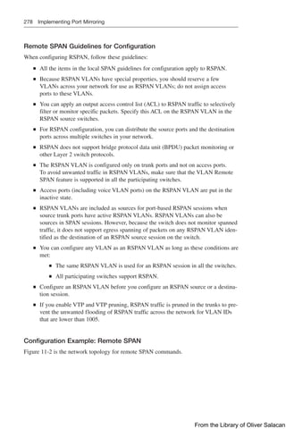
Configuring Remote SPAN
While local SPAN supports source and destination ports only on one switch, a remote
SPAN supports source and destination ports on different switches. RSPAN consists of an
RSPAN VLAN, an RSPAN source session, and an RSPAN destination session. You sepa-
rately configure RSPAN source sessions and destination sessions on different switches.
From the Library of Oliver Salacan](https://image.slidesharecdn.com/portablecommandguide-221029235346-67760e11/85/Portable-Command-Guide-pdf-300-320.jpg)
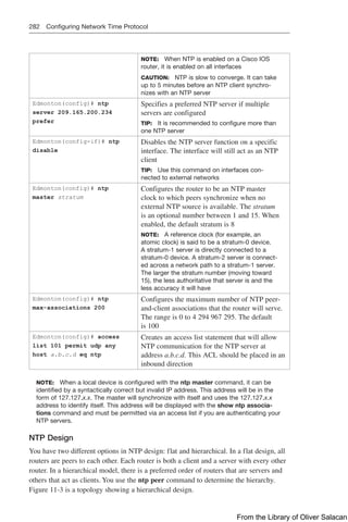
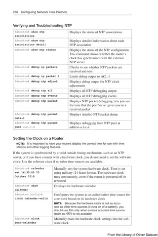
![Configuring Network Time Protocol 287
Edmonton# clock set
16:30:00 23 October
2019
Manually sets the system software clock. Time is set
using military (24-hour) format
Edmonton(config)#
clock summer-time
zone recurring [week
day month hh:mm week
day month hh:mm
[offset]]
Edmonton(config)#
clock summer-time
zone date date month
year hh:mm date month
year hh:mm [offset]
Edmonton(config)#
clock summer-time
zone date month date
year hh:mm month date
year hh:mm [offset]
Configures the system to automatically switch to sum-
mer time (daylight saving time)
NOTE: Summer time is disabled by default
Arguments for the command are as follows:
zone: Name of the time zone (see Tables 11-5 and 11-6
for alternative ways to specify the time zone)
recurring: Indicates that summer time should start and
end on the corresponding specified days every year
date: Indicates that summer time should start on the first
specific date listed in the command and end on the sec-
ond specific date in the command
week: (Optional) Week of the month (1 to 4 or last)
day: (Optional) Day of the week (Sunday, Monday, and
so on)
date: Date of the month (1 to 31)
month: (Optional) Month (January, February, and so on)
year: Year (1993 to 2035)
hh:mm: (Optional) Time (military format) in hours and
minutes
offset: (Optional) Number of minutes to add during sum-
mer time (default is 60)
Edmonton(config)#
clock timezone
zone hours-offset
[minutes-offset]
Configures the time zone for display purposes. To set
the time to Coordinated Universal Time (UTC), use the
no form of this command
zone: Name of the time zone to be displayed when stan-
dard time is in effect
hours-offset: Hours difference from UTC
minutes-offset: (Optional) Minutes difference from UTC
Edmonton(config)#
clock timezone
PST -8
Configures the time zone to Pacific Standard Time,
which is 8 hours behind UTC
Edmonton(config)#
clock timezone
NL -3 30
Configures the time zone to Newfoundland time for
Newfoundland, Canada, which is 3.5 hours behind UTC
Edmonton# clock
update-calendar
Updates the hardware clock from the software clock
Edmonton# show clock Displays the time and date from the system software
clock
Edmonton# show clock
detail
Displays the clock source (NTP, hardware) and the cur-
rent summer-time setting (if any)
From the Library of Oliver Salacan](https://image.slidesharecdn.com/portablecommandguide-221029235346-67760e11/85/Portable-Command-Guide-pdf-310-320.jpg)
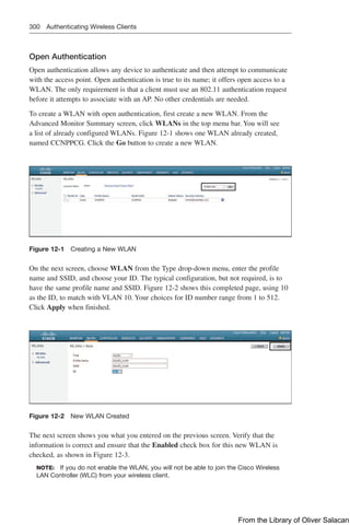
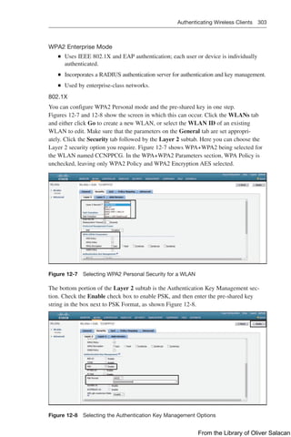
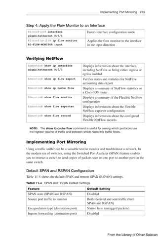
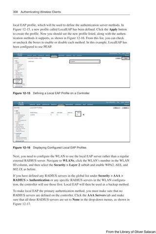
![304 Authenticating Wireless Clients
TIP: The controller will allow you to check both the WPA Policy and WPA2 Policy
check boxes. You should do this only if you have legacy equipment that requires WPA
support.
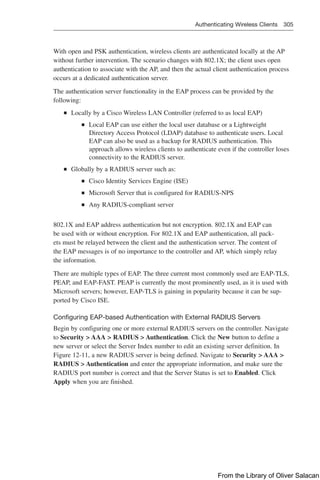
You can verify the security settings from the General tab for the WLAN. Click Apply to
commit the changes. Figure 12-9 shows the Security Policies for the CCNPPCG WLAN
have seen set to [WPA2][Auth(PSK)]. This is also shown in Figure 12-10.
Figure 12-9 Verifying PSK Authentication in WLAN Configuration
Figure 12-10 Verifying PSK Authentication in WLAN Summary Page
Authenticating with EAP
Rather than build additional authentication methods into the 802.11 standard, the
Extensible Authentication Protocol (EAP) offers a more flexible and scalable authenti-
cation framework. As its name implies, EAP is extensible and does not consist of any
one authentication method. Instead, EAP defines a set of common functions that actual
authentication methods can use to authenticate users.
EAP has another interesting quality: It can integrate with the IEEE 802.1X port-based
access control standard. When 802.1X is enabled, it limits access to a network media
until a client authenticates. This means that a wireless client might be able to associate
with an AP, but will not be able to pass data to any other part of the network until it suc-
cessfully authenticates.
From the Library of Oliver Salacan](https://image.slidesharecdn.com/portablecommandguide-221029235346-67760e11/85/Portable-Command-Guide-pdf-327-320.jpg)
![310 Authenticating Wireless Clients
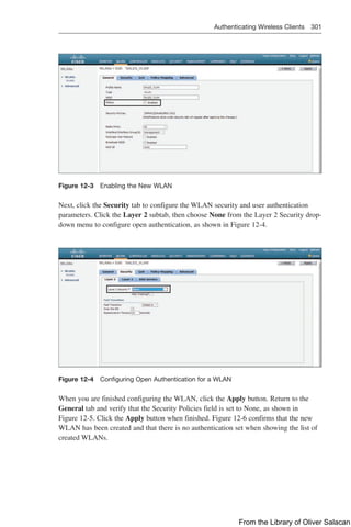
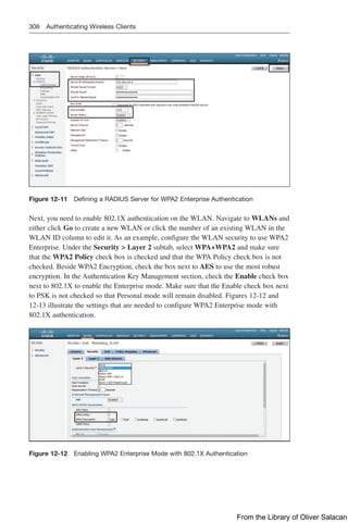
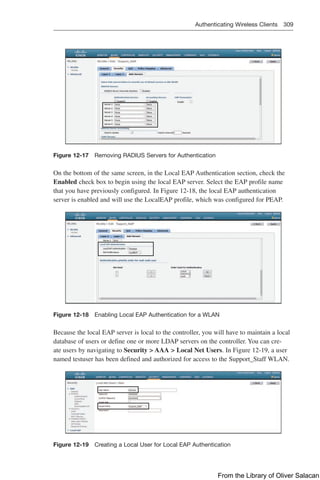
Verifying EAP-based Authentication Configuration
You can verify the WLAN and its security settings from the list of WLANs by select-
ing WLANs WLAN, as shown in Figure 12-20. For EAP-based authentication, the
Security Policies field should display [Auth(802.1X)]. You can also verify that the
WLAN status is enabled and active.
Figure 12-20 Verifying EAP Authentication on a WLAN
Authenticating with WebAuth
WebAuth is a process that allows users, typically guests, to authenticate to the network
through a web portal via a browser interface. Clients that attempt to access the WLAN
using HTTP are automatically redirected to a login page where they are prompted for
their credentials. Their credentials are then passed to an authentication server, which then
assigns the appropriate VLAN and ACLs for guest access to the Internet.
TIP: Web authentication can be handled locally on the WLC for smaller environments
through local web authentication (LWA). When there are many controllers providing
web authentication, it makes sense to use LWA with an external database on a RADIUS
server such as Cisco ISE, keeping the user database centralized.
To configure WebAuth on a WLAN, first create the new WLAN and map it to the correct
VLAN. Go to the General tab and enter the SSID string, apply the appropriate controller
interface, and change the status to Enabled.
On the Security tab, click the Layer 2 subtab to choose a wireless security scheme to be used
on the WLAN. In Figure 12-21, the WLAN is named Guest_webauth, the SSID is Guest_
webauth, and open authentication will be used because the None method has been selected.
Figure 12-21 Configuring Open Authentication for WebAuth
From the Library of Oliver Salacan](https://image.slidesharecdn.com/portablecommandguide-221029235346-67760e11/85/Portable-Command-Guide-pdf-333-320.jpg)
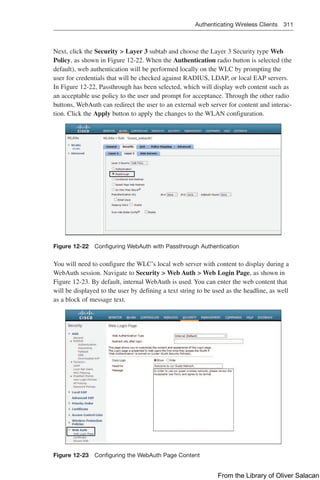
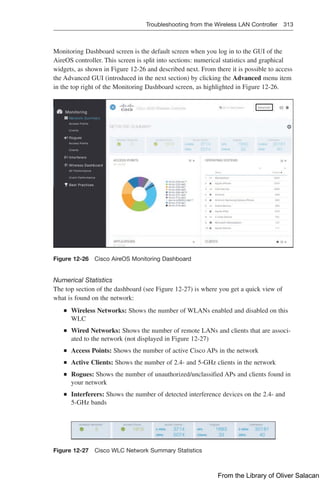
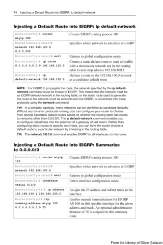
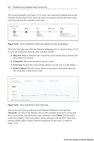
![316 Troubleshooting from the Wireless LAN Controller
Q
Q Monitoring: This menu includes options to view information about general con-
troller details, network services, and wireless APs and clients.
Q
Q Configuration: This menu includes options for configuring controller interfaces,
routing protocols, security, RF, network services, tags, profiles, and WLANs.
Q
Q Administration: This menu includes options for accessing the CLI, and configur-
ing DNS parameters, DHCP pools, licensing, software upgrades, and administra-
tive users.
Q
Q Troubleshooting: This screen enables you to access troubleshooting tools such as
syslog and debug, as well as packet capture, ping, and traceroute.
Figure 12-30 Cisco IOS XE GUI Dashboard
Cisco AireOS/IOS XE CLI
You may not always have access to the GUI of your Cisco Wireless LAN Controller,
so it is good to know a few CLI commands to quickly access important troubleshooting
information.
The Wireless LAN Controller CLI show commands to monitor the WLAN are listed in
the following table. When the show commands differ between AireOS and IOS XE, both
commands are listed in that order.
Clients
(Cisco Controller) show client
summary [ssid | ip | username |
devicetype]
Displays a summary of clients associ-
ated with a Cisco lightweight access
point
IOSXE# show wireless client summary
From the Library of Oliver Salacan](https://image.slidesharecdn.com/portablecommandguide-221029235346-67760e11/85/Portable-Command-Guide-pdf-339-320.jpg)
![Troubleshooting from the Wireless LAN Controller 317
(Cisco Controller) show client
detail mac-address
Displays client information learned
through DNS snooping, including cli-
ent username, associated AP, SSID, IP
address, supported data rates, mobility
state, security, and VLAN
IOSXE# show wireless client mac-
address mac-address detail
(Cisco Controller) show client ap
{802.11a | 802.11b} ap-name
Displays the clients on a radio for an
AP
IOSXE# show wireless client ap name
ap-name dot11 {24ghz | 5ghz}
Logs
(Cisco Controller) show traplog Displays the latest SNMP trap log
information
(Cisco Controller) show logging Displays the syslog facility logging
parameters, current log severity level,
and buffer contents
Radios
(Cisco Controller) show {802.11a |
802.11b | 802.11h}
Displays radio networking settings
(status, rates, supported, power, and
channel)
IOSXE# show ap dot11 {24ghz | 5ghz}
network
WLANs
(Cisco Controller)
IOSXE#
show wlan {apgroups | summary |
wlan-id | foreignAp | lobby-
admin-access}
Displays WLAN information (name,
security, status, and all settings).
Keywords include
apgroups: Displays access point
group information
summary: Displays a summary of all
WLANs
wlan_id: Displays the configuration of
a WLAN. The WLAN identifier range
is from 1 to 512
foreignAp: Displays the configuration
for support of foreign access points
lobby-admin-access: Displays all
WLANs that have lobby-admin-access
enabled
APs
(Cisco Controller) show ap config
{802.11a | 802.11b} [summary] ap-name
Displays AP detailed configuration
settings by radio
IOSXE# show ap dot11 {24ghz | 5ghz}
summary
From the Library of Oliver Salacan](https://image.slidesharecdn.com/portablecommandguide-221029235346-67760e11/85/Portable-Command-Guide-pdf-340-320.jpg)
![318 Troubleshooting from the Wireless LAN Controller
(Cisco Controller) show ap config
general ap-name
Displays general AP configuration
information
IOSXE# show ap name ap-name config
general
(Cisco Controller) show ap join
stats summary ap-mac
Displays MAC, IP address, name, and
join status of all APs joined
IOSXE# show ap mac-address mac-
address join stats {detailed | summary}
WLC# show ap join stats summary
(Cisco Controller)
IOSXE#
show ap summary [ap-name]
Displays APs (model, MAC, IP
address, country, and number of
clients)
(Cisco Controller) show ap wlan
{802.11a | 802.11b} ap-name
Displays WLAN IDs, interfaces, and
BSSID
IOSXE# show ap name ap-name wlan
dot11 {24ghz | 5ghz }
NOTE: When logging output from the Wireless LAN Controller, enter the config
paging disable command first to stop page breaks.
Just as with routers and switches, debug commands are available on the Cisco WLC.
One particular debug command that may be useful for troubleshooting wireless client
connectivity is debug client mac_address. It is a macro that enables eight debug com-
mands, plus a filter on the MAC address that is provided, so only messages that contain
the specified MAC address are shown. The eight debug commands show the most
important details about client association and authentication. The filter helps with situa-
tions where there are multiple wireless clients and too much output is generated, or the
controller is overloaded when debugging is enabled without the filter.
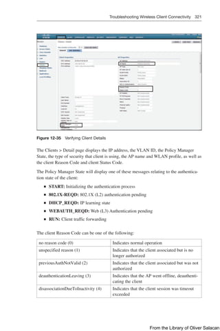
Troubleshooting Wireless Client Connectivity
If clients are reporting problems, a good place to start troubleshooting is at the Cisco
Wireless LAN Controller. This section shows the output from two different GUIs: the
Cisco AireOS Monitoring Dashboard GUI and the Cisco IOS XE GUI.
Cisco AireOS Monitoring Dashboard GUI
From the Monitoring pane along the left side of the AireOS Dashboard GUI, select
Network Summary Access Points to check if the APs are functioning correctly.
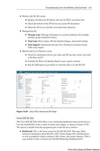
The Access Point View page, shown in Figure 12-31, is displayed when an AP is
selected. The AP details section provides tabs with information on the clients, RF
Troubleshooting with neighboring and rogue APs (2.4 and 5 GHz) found in the sur-
roundings, Clean Air with active interferers, and the tool tab to restart the AP.
From the Library of Oliver Salacan](https://image.slidesharecdn.com/portablecommandguide-221029235346-67760e11/85/Portable-Command-Guide-pdf-341-320.jpg)

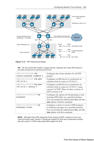
![344 VRF-Lite
Router(config-vrf-af)# exit Exits the IPv6 address family
Router(config-vrf)# exit Exits VRF configuration mode
Step 2: Assign an Interface to the VRF
Router(config)# interface
gigabitethernet 0/0/0
Enters interface configuration mode
Router(config-if)# ip vrf
forwarding GUEST
Assigns the GigabitEthernet 0/0/0
interface to the GUEST VRF using the
old CLI format
Router(config-if)# interface
gigabitethernet 0/0/1
Enters interface configuration mode
Router(config-if)# vrf forwarding
STAFF
Assigns the GigabitEthernet 0/0/1
interface to the STAFF VRF using the
new CLI format
Step 3: Enable Routing for the VRF
The following configuration examples demonstrate how IPv4 VRFs can be associated
with a routing process. The same commands would apply for IPv6 VRFs.
Router(config)# ip route vrf
GUEST 0.0.0.0 0.0.0.0 172.16.16.2
Defines a default route for the GUEST
VRF
Router(config)# router ospf 1 vrf
STAFF
Enables OSPFv2 for the STAFF VRF
Router(config)# router ospfv3 1 Enables OSPFv3
Router(config-router)# address-
family ipv4 unicast vrf STAFF
Assigns the STAFF VRF to the IPv4
unicast address family
Router(config)# router eigrp
CISCO
Enables EIGRP using named mode
configuration
Router(config-router)# address-
family ipv4 unicast vrf GUEST
autonomous-system 100
Assigns the GUEST VRF to the IPv4
unicast address family for AS 100
Router(config)# router bgp 65001 Enables BGP for AS 65001
Router(config-router)# address-
family ipv4 vrf STAFF
Assigns the STAFF VRF to the IPv4
address family
NOTE: Cisco IOS supports the old and new VRF CLI formats. Old Cisco IOS VRF con-
figuration style supports IPv4 only. New multiprotocol VRF CLI now supports both IPv4
and IPv6. Cisco IOS offers a migration tool that upgrades a VRF instance or all VRFs
configured on the router to support multiple address families under the same VRF. The
vrf upgrade-cli multi-af-mode {common-policies | non-common-policies} [vrf vrf-
name] command is issued in global configuration mode.
From the Library of Oliver Salacan](https://image.slidesharecdn.com/portablecommandguide-221029235346-67760e11/85/Portable-Command-Guide-pdf-367-320.jpg)


![[Cisco Connect 2018 - Vietnam] Cisco connect 2018 sanjay - cisco sda v1.0-h...](https://cdn.slidesharecdn.com/ss_thumbnails/ciscoconnect2018-sanjay-ciscosdav1-180504035424-thumbnail.jpg?width=640&height=640&fit=bounds)


