Qos For Ipmpls Networks Gallo Mark Zhang Raymond Alvarez Santiago
Qos For Ipmpls Networks Gallo Mark Zhang Raymond Alvarez Santiago
Qos For Ipmpls Networks Gallo Mark Zhang Raymond Alvarez Santiago
Qos For Ipmpls Networks Gallo Mark Zhang Raymond Alvarez Santiago
Qos For Ipmpls Networks Gallo Mark Zhang Raymond Alvarez Santiago
1.
Qos For IpmplsNetworks Gallo Mark Zhang Raymond
Alvarez Santiago download
https://ebookbell.com/product/qos-for-ipmpls-networks-gallo-mark-
zhang-raymond-alvarez-santiago-22009004
Explore and download more ebooks at ebookbell.com
3.
800 East 96thStreet
Indianapolis, IN 46240 USA
Cisco Press
QoS for IP/MPLS Networks
Santiago Alvarez
iii
Readers’ feedback isa natural continuation of this process. If you have any comments regarding how we could
improve the quality of this book, or otherwise alter it to better suit your needs, you can contact us through e-mail at
feedback@ciscopress.com. Please make sure to include the book title and ISBN in your message.
We greatly appreciate your assistance.
Publisher Paul Boger
Cisco Representative Anthony Wolfenden
Cisco Press Program Manager Jeff Brady
Production Manager Patrick Kanouse
Development Editor Jill Batistick
Senior Project Editor San Dee Phillips
Copy Editor Keith Cline
Technical Editors Mark Gallo, Raymond Zhang
Book and Cover Designer Louisa Adair
Composition Mark Shirar
Indexer Keith Cline
6.
iv
About the Author
SantiagoAlvarez, CCIE No. 3621, is a technical marketing engineering for Cisco Systems working on
MPLS and QoS since 2000. He joined Cisco in the blazing days of 1997. Prior to Cisco, Santiago
worked in software development for Lucent Technologies. He has been involved with computer net-
working since 1991. Santiago is a frequent speaker at Cisco Networkers and a periodic contributor to
Cisco Packet Magazine. He holds a bachelor of science degree in computer science from EAFIT Uni-
versity, a master of Science degree in computer science from Colorado State University, and a master
of science in telecommunications from the University of Colorado at Boulder. Outside work, he enjoys
the outdoors, fine food, and exploring the world as an independent traveler. He can be reached at
saalvare@cisco.com.
7.
v
About the TechnicalReviewers
Mark Gallo is a systems engineering manager at Cisco Systems within the channels organization. He
has led several engineering groups responsible for positioning and delivering Cisco end-to-end systems,
as well as designing and implementing enterprise LANs and international IP networks. He has a B.S.
degree in electrical engineering from the University of Pittsburgh and holds Cisco CCNP and CCDP
certifications. Mark resides in northern Virginia with his wife, Betsy, and son, Paul.
Raymond Zhang is a senior network architect for BT Infonet in the areas of Global IP backbone infra-
structure, routing architecture design, planning, and its evolutions. Currently, his main areas of interest
include large-scale backbone routing, traffic engineering, performance and traffic statistical analysis,
and MPLS-related technologies (including interdomain traffic engineering, GMPLS, metro Ethernet,
Diffserve, IPv6, and Multicast). Raymond participates in several IETF drafts relating to MPLS, BGP-
based MPLS VPN, Inter-AS TE, and, more recently, PCE-based work.
vii
Acknowledgments
I would liketo give special thanks to Bob Olsen and Sandeep Bajaj for sharing their technical expertise
through so many years. They have patiently tolerated my constant interruptions and have provided use-
ful insight on different topics included in the book.
Special thanks to the reviewers, Mark Gallo and Raymond Zhang. I appreciate your detailed comments.
I am to blame for any remaining inaccuracies or omissions.
Big thanks to Bruce Davie, whose responsiveness at key points encouraged me to persist in my goal. I
highly regard his unusual ability to abstract complexity and clearly illustrate the essence of intricate
technology concepts. Much of his work has directly and indirectly influenced the content of this book.
Similarly, I extend my gratitude to François Le Faucheur and Jean Philippe Vasseur. They have had the
patience to discuss with me many aspects of these technologies in numerous occasions. Merci!
Thanks to Ramesh Uppili for contributing to the presentation of key topics in multiple ways.
I also want to thank Rakesh Gandi, Prashanth Yelandur, Ashish Savla, Bobby Kaligotla, Lawrence
Wobker, Ashok Ganesan, Jay Thontakudi, and ScottYow for facilitating the discussion of Cisco IOS XR
in this book.
Special thanks to the Cisco Press team: John Kane, Chris Cleveland, Jill Batistick, San Dee Phillips, and
Elizabeth Peterson. I really appreciate your attention to detail and extraordinary patience with me. I
wish John the best in his new endeavors.
Finally, if you have read this far in search of your name, this paragraph is for you. I have to acknowledge
that numerous individuals contributed through insightful discussions. They unhappily or maybe happily
remain anonymous. Thanks!
10.
viii
This Book IsSafari Enabled
The Safari® Enabled icon on the cover of your favorite technology book means
the book is available through Safari Bookshelf. When you buy this book, you get
free access to the online edition for 45 days.
Safari Bookshelf is an electronic reference library that lets you easily search
thousands of technical books, find code samples, download chapters, and access
technical information whenever and wherever you need it.
To gain 45-day Safari Enabled access to this book:
• Go to http://www.ciscopress.com/safarienabled
• Complete the brief registration form
• Enter the coupon code 2ML4-YT1N-YR8J-D5NQ-DAH4
If you have difficulty registering on Safari Bookshelf or accessing the online
edition, please e-mail customer-service@safaribooksonline.com.
11.
ix
Contents at aGlance
Foreword xv
Introduction xvii
Chapter 1 QoS Technology Overview 3
Chapter 2 MPLS TE Technology Overview 57
Chapter 3 Cisco QoS 79
Chapter 4 Cisco MPLS Traffic Engineering 143
Chapter 5 Backbone Infrastructure 201
Appendix A Command Reference for Cisco MPLS Traffic Engineering and RSVP 265
Index 282
12.
x
Contents
Foreword xv
Introduction xvii
Chapter1 QoS Technology Overview 3
IP QoS Architectures 3
Integrated Services 4
IntServ Terminology 5
Architecture Principles 5
Service Model 6
Use of RSVP in IntServ 8
Differentiated Services 9
DiffServ Terminology 9
Architecture Principles 10
Differentiated Services Code Point 11
Nodes, Domains, and Regions 13
Traffic Classification and Conditioning 13
Per-Hop Behaviors 15
MPLS Support for IntServ 18
MPLS Support for DiffServ 19
E-LSP 20
L-LSP 22
DiffServ Tunneling Models over MPLS 25
Pipe Model 25
Short-Pipe Model 26
Uniform Model 28
Traffic-Management Mechanisms 31
Traffic Classification 31
Traffic Marking 31
Traffic Policing 32
Traffic Shaping 35
Congestion Management 37
Active Queue Management 40
Link Fragmentation and Interleaving 42
Header Compression 44
QoS Signaling 45
Resource Reservation Protocol 45
Design Principles 46
Protocol Messages 47
Protocol Operation 49
Other QoS Signaling Mechanisms 51
13.
xi
Summary 52
References 52
Chapter2 MPLS TE Technology Overview 57
MPLS TE Introduction 57
Basic Operation of MPLS TE 59
Link Information Distribution 59
Path Computation 60
TE LSP Signaling 63
Traffic Selection 64
DiffServ-Aware Traffic Engineering 64
Class-Types and TE-Classes 66
Bandwidth Constraints 68
Maximum Allocation Model 68
Russian Dolls Model 70
Fast Reroute 71
Link Protection 74
Node Protection 74
Summary 76
References 77
Chapter 3 Cisco QoS 79
Cisco QoS Behavioral Model 79
Classification Component 80
Pre-Queuing Component 80
Queuing Component 81
Enqueuing Subcomponent 81
Dequeuing Subcomponent 82
Post-Queuing Component 84
Modular QoS Command-Line Interface 84
Hardware Support for the MQC 87
Traffic-Management Mechanisms 87
Traffic Classification 88
Traffic Marking 94
Traffic Policing 100
Traffic Shaping 108
Congestion Management 115
Active Queue Management 121
Link Fragmentation and Interleaving 127
Header Compression 128
Hierarchical Configurations 129
Hierarchical Classification 129
14.
xii
Hierarchical Policies 130
Percentage-BasedRates 132
Parameter Units 133
Processing of Local Traffic 135
Summary 139
References 140
Chapter 4 Cisco MPLS Traffic Engineering 143
Basic Operation of MPLS TE 143
Enabling MPLS TE 144
Enabling MPLS TE on a Node 144
Enabling MPLS TE on an Interface 145
Defining a TE Tunnel Interface 146
Link Information Distribution 148
Using IS-IS for Link Information Distribution 148
Using OSPF for Link Information Distribution 149
Controlling Flooding 150
Configuring Link Attributes 150
Verifying Link Information Distribution 153
Path Computation 156
Configuring the TE LSP Path 156
Configuring the TE LSP Constraints 157
Path Reoptimization 159
Verifying Path Computation 160
Signaling of TE LSPs 163
Configuring RSVP 163
Verifying RSVP 164
Verifying Signaling of TE LSPs 167
Traffic Selection 172
Traffic-Selection Alternatives 172
Class-Based Tunnel Selection 173
DiffServ-Aware Traffic Engineering (DS-TE) 175
Prestandard DS-TE 175
Class-Types and TE-Class 176
Defining a DS-TE Tunnel Interface 177
Configuring Bandwidth Constraints 179
Verifying DS-TE Link Information Distribution 181
Verifying Signaling of DS-TE LSPs 182
Fast Reroute (FRR) 182
Link and Node Protection 183
Bandwidth Protection 187
15.
xiii
Verifying FRR onthe Headend 191
Verifying FRR on the PLR 193
Summary 198
References 198
Chapter 5 Backbone Infrastructure 201
Backbone Performance 201
Performance Requirements for Different Applications 202
Segmentation of Performance Targets 204
Factors Affecting Performance Targets 206
Latency Versus Link Utilization 207
Reference Network 210
Edge Nodes 210
QoS Design Alternatives 212
Best-Effort Backbone 213
Best-Effort Backbone with MPLS TE 219
DiffServ Backbone 226
DiffServ Backbone with MPLS TE 233
DiffServ Backbone with DiffServ-Aware Traffic Engineering 240
Adding MPLS TE FRR 251
What Design Should I Use? 260
Summary 261
References 261
Appendix A Command Reference for Cisco MPLS Traffic Engineering and RSVP 265
Index 282
16.
xiv
Icons Used inThis Book
Command Syntax Conventions
The conventions used to present command syntax in this book are the same conventions used in the IOS
Command Reference. The Command Reference describes these conventions as follows:
• Boldface indicates commands and keywords that are entered literally as shown. In actual
configuration examples and output (not general command syntax), boldface indicates commands
that are manually input by the user (such as a show command).
• Italics indicate arguments for which you supply actual values.
• Vertical bars (|) separate alternative, mutually exclusive elements. Note, however, that the vertical
bar (pipe operand) is also used to filter command-line interface command output; in that scenario,
the operand (|) precedes the begin, exclude, or include keywords, which are then followed by a
regular expression.
• Square brackets [ ] indicate optional elements.
• Braces { } indicate a required choice.
• Braces within brackets [{ }] indicate a required choice within an optional element.
PC PC with
Software
Sun
Workstation
Macintosh
Terminal File
Server
Web
Server
Cisco Works
Workstation
Printer Laptop IBM
Mainframe
Front End
Processor
Cluster
Controller
Modem
DSU/CSU
Router Bridge Hub DSU/CSU Catalyst
Switch
Multilayer
Switch
ATM
Switch
ISDN/Frame Relay
Switch
Communication
Server
Gateway
Access
Server
Network Cloud
Token
Ring
Token Ring
Line: Ethernet
FDDI
FDDI
Line: Serial Line: Switched Serial
17.
xv
Foreword
The phrase “IPQoS” was for many years considered an oxymoron. Indeed, much of the success of the
IP architecture could be traced to its adoption of a "best effort" service model, enabling IP to run over
just about any underlying network technology. Best effort service, however, is defined by a lack of
assurance that packets will be delivered in a timely manner, or even delivered at all. Such a service
model limits the potential of IP networks to support applications that demand timely packet delivery,
such as interactive telephony and multimedia applications.
As far back as 1979, there were proposals to extend the IP service model to support applications with
stronger QoS requirements. However, this remained a research topic until the early 1990s. By that point,
the idea of convergence—carrying many applications with diverse QoS needs on a single network—was
gaining currency, although the word “convergence” would not become a buzzword for several years.
ATM was widely expected to be the packet switching technology that would enable this convergence,
but a concerted effort to add QoS to IP was also getting underway. The seminal 1992 paper by Clark,
Shenker, and Zhang on support of real-time applications in the Internet put a serious stake in the ground
for IP QoS, and work at the IETF to standardize a set of IP QoS mechanisms began shortly thereafter.
The Integrated Services architecture and Resource Reservation Protocol resulted, and the Differentiated
Services architecture followed.
Another technical development with big implications for IP QoS was Multiprotocol Label Switching,
which grew out of work on Tag Switching at Cisco begun in 1996. There was considerable confusion
about exactly what impact MPLS would have on IP QoS, in part because of the resemblances between
MPLS and ATM, which had its own QoS model. In reality, the biggest single effect MPLS had on QoS
was to add another tool to the QoS toolbox, in the form of traffic engineering with constraint-based rout-
ing. It is for this reason more than any other that MPLS and QoS deserve to be covered in a single book.
Which brings us to the current volume. IP QoS can now be considered a mature technology, not just
something for the bleeding edge. It is also notoriously complex to understand and to configure cor-
rectly. Some of this complexity is intrinsic; some is an accident of history. On the intrinsic side, under-
standing QoS is hard because it requires the ability to operate at many different levels of abstraction.
One needs to understand the high level QoS architectures, to have a behavioral model of QoS features
inside a router, to know how those features map onto a particular piece of hardware, and to understand
the CLI that is used to control those features. This is where this book sets itself apart from the pack of
QoS books. Some cover QoS architecture and IETF standards. Some provide information on CLI com-
mands. But this is the only book I've found that walks the reader through the levels of abstraction from
high level architecture to low level CLI, with a clear explanation of the abstract QoS behavior model
that all routers support providing the bridge between the levels. By reading this book, you will under-
stand both the big picture of QoS and the details necessary to deploy it in a real network.
Another factor that made QoS difficult to manage in the past was a somewhat ad hoc approach to its
implementation. Combinations of features were sometimes implemented in a monolithic way, and
inconsistency across platforms was the norm. This situation has improved massively in recent years,
notably with the adoption of the Modular QoS CLI across most of the Cisco product line. Thus, QoS
deployment is much more straightfoward than it once was, and this book's timely coverage of the MQC
and its underlying behavioral model will make it even easier.
18.
xvi
Many readers maybe tempted to jump straight to the last chapter's guidance on how to design and
deploy a QoS strategy in a backbone network. Santiago's extensive real-world deployment experience
certainly makes this chapter especially valuable. However, the preceding four chapters are the ones that
will provide you with a fundamental understanding of QoS. Thus, rather than blindly following a QoS
"recipe," you'll be able to make the right design decisions to meet the needs of your own applications
and customers. If you really want to understand QoS fully, this is the book to read, from start to finish.
Bruce Davie
Cisco Fellow
.
19.
xvii
Introduction
The motivation behindthis book is the continued interest in the implementation of quality of service
(QoS) in IP/MPLS networks. QoS arises as a key requirement for these networks, which have become
the preferred technology platform for building converged networks that support multiple services. The
topic can be one of the most complex aspects of the network design, implementation, and operation.
Despite the importance of and interest in this topic, no other Cisco Press title provides a detailed discus-
sion of this subject. A significant amount of the content of this book also applies to pure IP networks
that do not have immediate plans to migrate to a full IP/MPLS network.
This material covers both QoS and Multiprotocol Label Switching Traffic Engineering (MPLS TE). In
particular, it covers MPLS TE as a technology that complements traditional QoS technologies. MPLS
TE can be an instrumental tool to improve the QoS guarantees that an IP/MPLS network offers. As
such, it can contribute to improving both network performance and availability. However, this book pro-
vides a concise discussion of MPLS TE. Those readers interested in further information should consult
the Cisco Press title Traffic Engineering with MPLS.
The book takes the point of view of those individuals responsible for the IP/MPLS network. Other Cisco
Press titles describe the details of the QoS implementation for those devices receiving the services that
the network offers.
You should have a basic understanding of both IP and MPLS to obtain the most benefit from this book.
That understanding should include basic IP addressing and routing, along with the basics of MPLS for-
warding. However, the book provides a technology overview of QoS and MPLS TE to help those with
less exposure to these technologies or to serve as a review/reference to those more familiar with those
topics.
This book touches a broad topic and does not pretend to address all QoS aspects of interest. You can
expect future Cisco Press books to cover important areas, including the following:
• Implementation of QoS for specific services (for instance, IP, Ethernet, ATM)
• QoS management (including monitoring and provisioning)
• Interprovider QoS
Visit this book’s website, http://www.ciscopress.com/title/1587052334, for further information.
20.
xviii
Who Should ReadThis Book?
This book’s primary audience is the technical staff of those organizations building IP/MPLS networks
as an infrastructure to provide multiple services. The material includes technology, configuration, and
operational details to help in the design, implementation, and operation of QoS in IP/MPLS networks.
Service providers are a prime example of the organizations that this book targets. However, government
agencies, educational institutions, and large enterprises pursuing IP/MPLS will find the material equally
useful.
A secondary audience for this book is those individuals in charge of service definition or those individu-
als subscribing to network services. Both types can benefit from a better understanding of the differenti-
ation capabilities that IP/MPLS networks can offer.
How This Book Is Organized
Although this book could be read cover to cover, it is designed to be flexible and allow you to easily
move between chapters and sections of chapters to cover just the material that you need more work
with. The content is roughly divided into three parts:
• Chapters 1 and 2 provide a technology overview.
• Chapters 3 and 4 discuss Cisco implemenation.
• Chapter 5 covers different backbone design options.
Here is a brief synopsis of each chapter:
Chapter 1, “QoS Technology Overview”—This chapter provides a review of QoS technology for IP
and IP/MPLS networks. The chapter initially discusses the IP QoS architectures and how they apply to
MPLS. Multiple sections elaborate on MPLS support for Differentiated Services (DiffServ), including a
detailed discussion on EXP-inferred-class link switched path (E-LSP), Label-inferred-class LSP (L-
LSP), and DiffServ tunneling models (pipe, short pipe, and uniform). This dicussion leads into a sum-
mary of traffic-management mechanisms with a detailed look at traffic policing, traffic shaping, traffic
scheduling, active queue manangemt, and so on. The chapter also discusses QoS signaling with a focus
on the Resource Reservation Protocol (RSVP).
Chapter 2, “MPLS TE Technology Overview”—This chapter reviews the basic operation of this tech-
nology with its DiffServ extensions and applicability as a traffic-protection alternative. This review
elaborates on the concepts of contraint-based routing, DiffServ-aware Traffic Engineering (DS-TE) and
fast reroute (FRR) (including link, shared-risk link group, and node protection).
Chapter 3, “Cisco QoS”—This chapter covers the Cisco QoS behavioral model and the modular QoS
command-line interface (MCQ). The chapter abstracts the platform specifics to facilitate the under-
standing of Cisco QoS and provides a complete reference of the configuration commands. In addition,
the chapter includes numerous examples to illustrate the configuration and verification of different traf-
fic-management mechanisms in Cisco IOS and Cisco IOS XR. This material is equially relevant to IP
and IP/MPLS networks.
21.
xix
Chapter 4, “CiscoMPLS Traffic Engineering”—This chapter presents Cisco implementation of
MPLS Traffic Engineering in both Cisco IOS and Cisco IOS XR. It includes multiple configuration and
verification examples illustrating the implementation of basic MPLS TE, DS-TE, and FRR.
Chapter 5, “Backbone Infrastructure”—This chapter discusses the backbone performance require-
ments and the different design options. The chapter reviews different designs, ranging from a best-effort
backbone to the most elaborate scenarios combining DiffServ, DS-TE, and FRR. Numerous configura-
tion examples illustrate their implementation using Cisco IOS and Cisco IOS XR.
23.
C H AP T E R
1
QoS Technology Overview
In this chapter, you review the following topics:
• IP QoS Architectures
• MPLS Support for IntServ
• MPLS Support for DiffServ
• Traffic-Management Mechanisms
• QoS Signaling
This chapter provides a review of the key technology components of quality of service
(QoS) in IP/MPLS networks. This review discusses the IntServ and DiffServ architectures
including their relationship with MPLS. The chapter covers the traffic management
mechanisms that enable QoS implementation and reviews different QoS signaling
alternatives in IP/MPLS with a special focus on RSVP protocol.
This book assumes that you are already familiar with the basic concepts behind these
topics. You should also be familiar with the basics of Multiprotocol Label Switching
(MPLS) in general. This chapter and Chapter 2, “MPLS TE Technology Overview,” serve
as a technology review and quick reference for later content. Chapter 3, “Cisco QoS,”
covers the specifics on Cisco implementation of QoS technology. The “References” section
at the end of this chapter lists sources of additional information on the topics that this
chapter covers.
IP QoS Architectures
Originally, IP was specified a best-effort protocol. One of the implications of this service
definition was that the network would attempt to deliver the traffic to its destination in the
shortest time possible. However, the network would provide no guarantee of achieving it.
This service definition proved successful during the early Internet years, when data
applications constituted the bulk of Internet traffic. Generally, these applications used TCP
and therefore adapted gracefully to variations in bandwidth, latency, jitter, and loss. The
amount of interactive traffic was minimal, and other applications requiring stricter
guarantees were at an experimental stage.
24.
4 Chapter 1:QoS Technology Overview
However, a new generation of applications with new service requirements emerged as the
Internet grew in success. The increasing reach and capacity of the Internet made it an
attractive infrastructure to support an increasing number of applications. In addition,
corporations, governments, and educational institutions, among others, found the IP
protocol an appealing option to build their private data networks. Many of the new IP
applications (for example, voice and video) had a real-time nature and limited tolerance to
variations in bandwidth, latency, jitter, and loss. The service expectations of network users
and their application requirements made the best-effort service definition insufficient.
The definition of a QoS architecture started in the middle of the 1990s. Since then, the
Internet Engineering Task Force (IETF) has defined two QoS architectures for IP:
Integrated Services (IntServ) and Differentiated Services (DiffServ). The IntServ
architecture was the initial proposed solution. Subsequently, the DiffServ architecture came
to life. MPLS later incorporated support for the DiffServ architecture, which the IETF had
defined exclusively for IP.
These two architectures use different assumptions and take different approaches to bringing
QoS to IP.Although sometimes considered opposite and competing architectures, they tend
to complement each other. Moreover, the QoS mechanisms used ultimately to manipulate
traffic are essentially the same in both architectures.
Integrated Services
The IntServ working group was responsible for developing the specifications of this
architecture at the IETF. The group met for the first time during the twenty-ninth IETF in
1994. The architecture specifications have a close relationship with the work of the IntServ
over Specific Link Layers (ISSLL) and the Resource Reservation Protocol (RSVP) working
groups. The ISSLL working group defined the implementation of IntServ over different
link-layer protocols (for example, Ethernet and ATM). The RSVP working group defined
the RSVP protocol that the IntServ group selected as the signaling protocol. The three
working groups collectively produced 32 RFCs, of which 24 are in the IETF standards
track. The working groups eventually closed between the years 2000 and 2002.
The IETF decided to modify the original Internet architecture to support real-time
applications. The IETF considered simpler alternatives, but they offered less-complete
solutions. For instance
• Fair-queuing algorithms solved the unfairness between data and real-time
applications, but they could not guarantee the delay and jitter.
• The use of separate networks for separate services was less efficient due to the lower
levels of statistical multiplexing.
• Bandwidth overprovisioning was not a realistic solution when bandwidth was offered
as a service.
25.
IP QoS Architectures5
• A simple priority mechanism could not prevent a growing number of real-time flows
from causing degradation of all flows.
• The rate and delay adaptation of real-time applications had limits, especially when no
admission control was used.
IntServ Terminology
This section lists several important terms that IntServ introduces. The next two sections
provide more detail about these abstractions:
• Flow—An identifiable stream of packets that a network node associates with the same
request for QoS. A flow may span a single or multiple application sessions.
• Traffic specification (TSpec)—Characterization of the traffic pattern of a flow over
time.
• Service request specification (RSpec)—Characterization of the QoS a flow desires.
• Flow specification (flowspec)—Combination of a TSpec and an RSpec. Network
nodes use the flowspec as input for admission-control decisions.
Architecture Principles
A crucial principle of the IntServ architecture is the requirement for resource reservation.
This requirement implies admission control to manage finite resources. IntServ nodes need
to avoid accepting unauthorized requests or requests that can affect existing reservations
with service commitments. Different types of users are expected to have different rights to
reserve network resources. In addition, the network load has to be controlled to meet the
quantitative specification of the service-quality commitments of existing flows. IntServ
leaves the selection of the QoS to the application rather than the network.
The architecture defines a flow as the basic service unit. This abstraction represents a
distinguishable stream of packets that requires the same QoS. Flows are unidirectional.
They have a single source and one or many destinations. IntServ requires the use of per-
flow state in network nodes. This requirement results from the flow granularity and the use
of resource reservation with admission control. Having network nodes maintaining per-
flow state represents a significant change to the original IP architecture that left per-flow
state to end systems. The architecture recommends the use of a signaling protocol to set up
and refresh the state to preserve the robustness of the IP protocol. RFC 1633 introduces the
architecture. Figure 1-1 shows a simple example of an IntServ network.
26.
6 Chapter 1:QoS Technology Overview
Figure 1-1 Overview of a Network Implementing IntServ
Service Model
The IntServ architecture defines an extensible service model with a common framework.
An important component of the definition of a service is the information that the receiver,
which requests the service, must specify to the network.A service request includes a TSpec
and, possibly, an RSpec. When a service request is accepted, the network nodes must
guarantee the service as long as the TSpec continues to describe the flow. The combination
of a TSpec and an RSpec receives the name of flowspec.
The architecture service model uses a common TSpec definition. Four parameters
characterize the traffic:
• A token bucket (r, b)—The token bucket includes a token rate (r) and a token bucket
size (b).
• A peak rate (p)—Flow traffic may not arrive at a rate higher than the peak rate.
• A minimum policed unit (m)—Network nodes treat packets of a size smaller than
the minimum policed unit as packets of size m. This term facilitates the estimation of
the actual bandwidth that a flow requires (including the Layer 2 header overhead).
• A maximum packet size (M)—A node considers packets with a size larger than M
as packets that do not conform to the traffic specification. Those nonconforming
packets might not receive the same service as conforming packets.
RSVP
Endpoint
RSVP
Endpoint
Flow
Signaling
Message
RSVP
State
RSVP
State
RSVP
State
Signaling
Message
27.
IP QoS Architectures7
Table 1-1 summarizes the TSpec parameters.
NOTE The token bucket is an important concept in traffic management. The sections “Traffic
Policing” and “Traffic Shaping” describe it in more detail later in this chapter.
The architecture defined two services: Guaranteed Service (GS) and Controlled Load
Service (CLS). They complement the best-effort service that is part of the definition of the
IP protocol. IntServ does not introduce any changes to the operation of the best-effort
service. In addition, the IntServ service model does not mandate a particular implemen-
tation for the traffic-management mechanisms that implement a service. The next two
sections explain the GS and CLS services, focusing on their end-to-end behavior and their
flow specifications.
NOTE RFC 2997 later defined a Null Service type. Applications can use this service to let the
network determine the appropriate service parameters for the flow. This service type has
special applicability for the integration of IntServ and DiffServ architectures.
Guaranteed Service
GS provides flows with a delay and bandwidth guarantee. GS ensures a firm bound on the
maximum end-to-end queuing delay for packets that conform to the flowspec. Furthermore,
a properly policed flow should not experience queuing drops in the absence of network
failures or routing changes. The service does not consider fixed-delay components that are
a property of the flow path (for example, propagation delay or serialization delay). A flow
receives guaranteed service if all nodes along the path support the service. GS does not
guarantee an average or minimum delay, just a maximum bound. Therefore, this service
does not provide any jitter guarantees. RFC 2212 defines GS.
Table 1-1 TSpec Parameters
Parameter Description
r Token rate
b Token bucket size
p Peak rate
m Minimum policed unit
M Maximum packet size
28.
8 Chapter 1:QoS Technology Overview
A receiver provides a TSpec and an RSpec when requesting GS. The RSpec contains a
service rate (R) and a time slack (S). Network nodes must approximate the service that a
dedicated line at that rate would provide to the flow. Nodes make available the margin of
error of their approximation. Applications can use this information to compute the
maximum end-to-end delay that the flow will experience. The slack term in the RSpec
specifies the incremental end-to-end delay that the sender can tolerate if a node modifies
the flow resource allocation. Applications can adjust the flowspec if the delay bound is not
acceptable. Table 1-2 summarizes the RSpec parameters.
Control Load Service
CLS approximates the behavior of best-effort service during unloaded conditions. Network
nodes satisfy this behavior even in the presence of congestion.Applications can assume that
the network will deliver a high percentage of all packets to their final destination. In
addition, applications can assume that a high percentage of the delivered packets will
experience a delay that will not greatly exceed the minimum delay of any packet.
Applications do not receive any target values for packet delay or loss. This service supports
those applications that operate satisfactorily with a best-effort service but are highly
sensitive to congestion conditions. Applications do not require an RSpec to request CLS,
only the flow TSpec. RFC 2211 introduces CLS.
Use of RSVP in IntServ
IntServ can use RSVP as the reservation setup protocol. One of the principles of this
architecture is that applications communicate QoS requirements for individual flows to the
network. These requirements are used for resource reservation and admission control.
RSVP can perform this function. However, RSVP is frequently but inaccurately equated to
IntServ. RSVP and IntServ share a common history, but they are ultimately independent.
Two separate working groups at the IETF developed their specifications. RSVP has
applicability as a signaling protocol outside IntServ. Similarly, IntServ could use other
signaling mechanisms. The section “Resource Reservation Protocol” explains the protocol
details later in this chapter. RFC 2210 describes how IntServ uses RSVP and defines the
RSVP objects to implement the IntServ service model.
Table 1-2 RSpec Parameters
Parameter Description
R Service rate
S Time slack
29.
IP QoS Architectures9
Differentiated Services
The DiffServ working group was responsible for the definition of this architecture at the
IETF. The group met for the first time during the forty-first IETF in 1998. The working
group was created with a charter to produce an architecture with a simple and coarse QoS
approach that applied to both IPv4 and IPv6. The charter explicitly excluded microflow
identification and signaling mechanisms (marking an explicit departure from the approach
taken by IntServ). The working group produced 12 RFCs, with five of them being in the
standards track and the rest being informational. The group eventually closed after its last
meeting in 2001.
NOTE An IP traffic stream with a unique combination of source address, destination address,
protocol, source port, and destination port defines a microflow.
DiffServ Terminology
The DiffServ architecture introduces many new terms. This section presents a simplified
definition of a selected few of them. The upcoming sections explain the terms in more
detail. RFC 2475 and 3260 introduce the complete list of terms:
• Domain—A network with a common DiffServ implementation (usually under the
same administrative control).
• Region—A group of contiguous DiffServ domains.
• Egress node—Last node traversed by a packet before leaving a DiffServ domain.
• Ingress node—First node traversed by a packet when entering a DiffServ domain.
• Interior node—Node in a DiffServ domain that is not an egress or ingress node.
• DiffServ field—Header field where packets carry their DiffServ marking. This field
corresponds to the six most significant bits of the second byte in the IP header
(formerly, IPv4 TOS [Type-of-Service] octet and IPv6 Traffic Class octet).
• Differentiated Services Code Point (DSCP)—A specific value assigned to the
DiffServ field.
• Behavior aggregate (BA)—Collection of packets traversing a DiffServ node with the
same DSCP.
• Ordered aggregate (OA)—A set of BAs for which a DiffServ node must guarantee
not to reorder packets.
• BA classifier—Classifier that selects packets based on DSCP.
• Multifield (MF) classifier—Classifier that selects a packet based on multiple fields
in the packet header (for example, source address, destination address, protocol, and
protocol port).
30.
10 Chapter 1:QoS Technology Overview
• Per-hop behavior (PHB)—Forwarding behavior or service that a BA receives at a
node.
• Per-hop behavior group—One or more PHBs that are implemented simultaneously
and define a set of related forwarding behaviors.
• PHB scheduling class (PSC)—A set of PHBs for which a DiffServ node must
guarantee not to reorder packets.
• Traffic profile—Description of a traffic pattern over time. Generally, in terms of a
token bucket (rate and burst).
• Marking—Setting the DSCP in a packet.
• Metering—Measuring of a traffic profile over time.
• Policing—Discarding of packet to enforce conformance to a traffic profile.
• Shaping—Buffering of packets to enforce conformance to a traffic profile.
• Service level agreement (SLA)—Parameters that describe a service contract
between a DiffServ domain and a domain customer.
• Traffic-conditioning specification—Parameters that implement a service level
specification.
• Traffic conditioning—The process of enforcing a traffic conditioning specification
through control functions such as marking, metering, policing, and shaping.
NOTE This DiffServ section is consistent with the original architecture terms. Note, however, that
Cisco documentation considers metering an implicit component of traffic shaping and
policing. Furthermore, it regards dropping as just one of three possible actions (transmit,
drop, mark) of a policer. The remainder of the book follows the policing and shaping
definitions used in Cisco documentation.
Architecture Principles
The DiffServ architecture relies on the definition of classes of traffic with different service
requirements. A marking in the packet header captures the traffic classification. Further
network nodes inspect this marking to identify the packet class and allocate network
resources according to locally defined service policies. The service characteristics are
unidirectional with a qualitative description in terms of latency, jitter, and loss. DiffServ
nodes are stateless from a QoS point of view and have no knowledge of individual flows.
Relatively few packet markings are possible with respect to the number of microflows that
a node may be switching at a given point in time. However, the concept of grouping or
aggregating traffic into a small number of classes is inherent to DiffServ. The architecture
intentionally makes a tradeoff between granularity and scalability. RFC 2475 introduces the
architecture.
31.
IP QoS Architectures11
Providing different levels of service using aggregate classification and marking is not a
novel concept. As an analogy, consider a transoceanic commercial flight with multiple
classes of service. During the check-in process, the passenger needs to provide some
identification information (classification criteria). Based on this information, the agent
identifies the passenger class (for instance, first, business, or tourist) and provides a
boarding pass that reflects the assigned class (marking). The customer class influences the
service the passenger receives during the duration of the flight (including access to airline
lounge, boarding priority, in-flight service, and deboarding priority). The reduced number
of classes allows the airline to provide some differentiation to customers without having to
provide a totally individualized service to each passenger. As you can probably recognize,
this is not the only instance of aggregate classification and marking used in real life.
Differentiated Services Code Point
Previous specifications of the IP protocol had already reserved header bits for QoS
purposes. The IP version 4 specifications in RFC 791 defined the second header octet as the
TOS octet. Also, the IP version 6 specifications in RFC 2460 defined the second header
octet as the Traffic Class octet but with an undefined structure. In the original TOS octet in
IP version 4, the three most significant bits specified the packet precedence (an indication
of the relative importance or priority). The next 3 bits in the TOS octet indicated the delay,
throughput, and reliability requirements. The final two (least significant) bits were
undefined and set to zero. RFC 1349 introduced a small change in the TOS octet by defining
a field that included a cost bit plus the existing delay, throughput, and reliability bits.
Similarly, the IP version 6 specifications in RFC 2460 define the second header octet as the
Traffic Class octet but with an undefined structure. Figure 1-2 illustrates these now-obsolete
definitions.
The DiffServ architecture redefines the IPv4 TOS octet and the IPv6 Traffic Class octet.
RFC 2474 and RFC 3260 name the DiffServ field as the six most significant bits in the
previous IPv4 TOS and IPv6 Traffic Class octets. A particular value of the DiffServ field
represents a DSCP. A DiffServ node services packets according to this code point. A group
of packets sharing the same DSCP and traversing a link in a specific direction constitutes a
BA. A class of traffic may include one or more BAs.
The architecture defines three code point pools for the DiffServ field. Two pools,
representing 32 out of the 64 possible values, are reserved for experimental or local use.
The existing DiffServ specifications provide recommendations for 21 out of the 32 code
points available in the third pool.
The section “Per-Hop Behaviors” in this chapter introduces these values and their service
definitions. Eight (class selector) code points provide backward compatibility with the
previous Precedence field in the TOS octet. The DiffServ field does not provide any
backward compatibility with the TOS field (delay, throughput, and reliability bits)
previously defined in the TOS octet. Figure 1-3 shows the structure of the new DiffServ
field, the code point pools, and the class selector code points.
32.
12 Chapter 1:QoS Technology Overview
Figure 1-2 Previous Definitions of the TOS Octet for IPv4 and IPv6 That DiffServ Makes Obsolete
Figure 1-3 DiffServ Field, Code Point Pools, and Class Selector Code Points
Precedence D
0 1 2 3 4 5 6 7
T R 0 0
RFC 791
Precedence
111 – Network Control
110 – Internetwork Control
101 – CRITIC / ECP
100 – Flash Override
011 – Flash
010 – Immediate
001 – Priority
000 – Routine
Delay (D)
0 – Normal
1 – Low
Throughput (T)
0 – Normal
1 – High
Reliability (R)
0 – Normal
1 – High
T r a f f i c c l a s s
0 1 2 3 4 5 6 7
RFC 2460
Precedence
0 1 2 3 4 5 6 7
T O S 0
RFC 1349
Precedence
111 – Network Control
110 – Internetwork Control
101 – CRITIC / ECP
100 – Flash Override
011 – Flash
010 – Immediate
001 – Priority
000 – Routine
TOS Field
1000 – minimize delay
0100 – maximize throughput
0010 – maximize reliability
0001 – minimize monetary cost
0000 – normal service
D i f f S e r v F i e l d
0 1 2 3 4 5 6 7
RFC 2474
RFC 3260
DiffServ Field
Codepoint Pools
xxxxx0 – Standard
xxxx11 – Experimental or local use
xxxx01 – Future standard,
experimental or local use
DiffServ Codepoints
111000 – Class Selector 7
110000 – Class Selector 6
101000 – Class Selector 5
100000 – Class Selector 4
011000 – Class Selector 3
010000 – Class Selector 2
001000 – Class Selector 1
000000 – Class Selector 0
33.
IP QoS Architectures13
Nodes, Domains, and Regions
The DiffServ architecture defines a hierarchy that goes from a single device, to a network,
to a group of networks. A set of nodes with a common DiffServ implementation forms a
domain. The nodes inside a domain perform similar service definitions and policies. A
domain is typically under a single administrative control. A set of contiguous domains
defines a DiffServ region. The domains within the region must be able to provide DiffServ
to traffic traversing the different domains in the region. Individual domains may use
different service definitions, policies, and packet markings. In those cases, the domains
must have peering agreements that specify how traffic is handled when crossing domains.
Boundary nodes and interior nodes constitute the two main types of nodes that reside in a
DiffServ domain. Boundary nodes interface with the outside of the domain and ensure that
any traffic is properly classified, marked, and within the agreed amounts. DiffServ defines
these operations as traffic classification and conditioning. Boundary and interior nodes
implement local service policies according to the packet marking. These local policies
provide different levels of service to each BA that DiffServ calls PHBs. The section “Per-
Hop Behaviors” discusses this concept in detail. A domain may have some nodes that do
not support DiffServ. The service impact of these nodes depends on their number and their
location within a domain. Figure 1-4 illustrates a DiffServ region with two domains.
Traffic enters a domain at an ingress boundary node and leaves the domain at an egress
boundary node. The ingress boundary node typically performs the traffic-classification and
conditioning function according to a specification or contract. Boundary nodes generally
act as both ingress and egress nodes because traffic differentiation is desirable for the traffic
that flows in both directions.
Traffic Classification and Conditioning
Traffic classification and conditioning identifies the traffic that will receive a differentiated
service and ensures that it conforms to a service contract. Outside nodes connecting to the
DiffServ domain have agreed to some service terms that the architecture defines as an SLA.
The boundary node enforces this SLA, or contract, using traffic classification and
conditioning. This enforcement uses a combination of packet classification, marking,
metering, shaping, and policing to ensure that the traffic conforms to the contract terms.
34.
14 Chapter 1:QoS Technology Overview
Figure 1-4 Functional View of Nodes and Domains in a DiffServ Region
NOTE RFC 3260 refined the initial DiffServ definition of SLA and introduced a new term, service
level specification (SLS). Even though the term clarification is useful, this book uses the
term SLA (which is more commonly used).
Traffic classification is the first action that a boundary node performs on traffic entering the
domain. The boundary node examines the packet and, according to the SLA terms,
implements an appropriate action (for example, marking, metering, policing). The
architecture describes two types of classifiers: BA classifier and MF classifier. The BA
classifier classifies packets using the DSCP in the packet. The MF classifier classifies
packets using one or more fields of the packet header (for example, source IP address,
destination IP address, protocol, source port, destination port) and other packet information
(for example, input interface). The final result of packet classification is the local
association of each packet with a class.
NOTE The DiffServ architecture did not consider packet payload as input for packet classification.
Actual implementations support packet classification using payload inspection and other
classification criteria.You can consider those classifiers as an extension of the MF classifiers.
Region
Direction of Traffic Flow
Ingress
Boundary
Node
Egress
Boundary
Node
Interior
Node
Upstream
Domain
Downstream
Domain
Ingress
Boundary
Node
Egress
Boundary
Node
Interior
Node
35.
IP QoS Architectures15
The boundary node conditions packets according to the SLA after classification. Traffic
conditioning involves a combination of one or more of the following mechanisms:
metering, marking, policing, or shaping. This conditioning process uses the result of the
packet classification as input. Conditioning may vary from class to class. SLAs typically
define a limit on the amount of traffic that the boundary node will take for each class. In
those cases, the boundary node measures the traffic and makes a marking, dropping, or
buffering decision on the packet. Conditioning must set the DSCP of each packet to an
appropriate value. Downstream nodes typically rely on this DSCP for fast packet
classification. The sections “Traffic Policing” and “Traffic Shaping” provide more details
on conditioning mechanisms.
Traffic classification and conditioning may happen at different points of a packet path. In
general, boundary nodes perform these tasks. However, the architecture does not preclude
interior nodes from doing complex classification and conditioning if needed (for example,
on international links). Figure 1-5 shows an example in which the ingress boundary node
of the upstream domain uses MF classifiers and conditions separately the traffic that A and
B generate. Marking packets close to the source facilitates application differentiation and
simplifies classification on downstream nodes. In this example, the ingress boundary node
of the downstream domain conditions the aggregate traffic that it receives. The ingress node
relies on the classification and marking that the upstream domain performed. The egress
boundary nodes may also perform traffic conditioning.
Figure 1-5 Illustration of SLA Enforcement Across Two DiffServ Domains
Per-Hop Behaviors
The DiffServ architecture defines a PHB as the forwarding behavior that a node applies to
a BA. It represents a qualitative description of the latency, jitter, or loss characteristics that
a BA will experience while traversing a DiffServ node. The PHB definition does not
BA classification and
aggregate conditioning
enforce SLA between
domains
MF classification and
conditioning enforce a
separate SLA for each
source.
A
B
Ingress
Boundary
Node
Egress
Boundary
Node
Upstream
Domain
Downstream
Domain
Ingress
Boundary
Node
Egress
Boundary
Node
IP
36.
16 Chapter 1:QoS Technology Overview
quantify these characteristics. A PHB group contains one or more related PHBs that are
implemented simultaneously.
DiffServ nodes map packets to PHBs according to their DSCP. Table 1-3 shows the
mappings that the architecture specifications recommend. DiffServ does not mandate these
DSCP-to-PHB mappings. It provides the flexibility to confiugure arbitrary mappings if
desired. Class selectors are the only exception, because the architecture defines them for
backward compatibility with the use of the Precedence field in the IPv4 TOS octet. DiffServ
domains not using the recommended mappings are more likely to have to re-mark traffic
when interfacing with other DiffServ domains and experience greater operational
complexity.
Table 1-3 IETF-Recommended Mapping Between PHBs and DSCPs
PHB DSCP (Decimal) DSCP (Binary)
EF 46 101110
AF43 38 100110
AF42 36 100100
AF41 34 100010
AF33 30 011110
AF32 28 011100
AF31 26 011010
AF23 22 010110
AF22 20 010100
AF21 18 010010
AF13 14 001110
AF12 12 001100
AF11 10 001010
CS7 56 111000
CS6 48 110000
CS5 40 101000
CS4 32 100000
CS3 24 011000
CS2 16 010000
CS1 8 001000
Default 0 000000
37.
IP QoS Architectures17
A number of PHB or PHB groups are part of the current DiffServ specifications: Expedited
Forwarding (EF), Assured Forwarding (AF1, AF2, AF3, and AF4), Class Selector (CS),
and Default. A node may support multiple PHB groups simultaneously. Nodes implement
these PHBs using packet-buffering and scheduling mechanisms that the section “Traffic-
Management Mechanisms” discusses.
Expedited Forwarding
The EF PHB defines a low-latency, low-jitter, and low-loss behavior that a DiffServ node
may implement. This PHB acts as a building block for the transport of real-time traffic over
a DiffServ domain. To support this behavior, a DiffServ node must serve EF traffic at a rate
that is higher than its arrival rate, independently of the amount of non-EF traffic. This
difference between the EF arrival and service rate helps ensure that EF traffic encounters
empty or near-empty queues, which minimizes the queuing latency. This type of latency is
generally the main contributor to packet latency and jitter during normal node operation.
Minimization of queuing latency results in not only low latency and low jitter but also in
low loss, because it prevents exhaustion of packet buffers. A DiffServ node should not
cause any packet reordering within EF microflows. RFC 3246 and RFC 3247 define and
discuss this PHB in detail.
Assured Forwarding
The AF family of PHB groups defines four different levels of forwarding guarantee that a
DiffServ node may support. In simpler terms, these groups define how a DiffServ node may
support different packet-loss guarantees. TheAF PHB groups receive the names:AF1,AF2,
AF3, and AF4. Each of these groups supports three drop-precedence levels. The higher the
drop precedence, the more likely a DiffServ node will drop the packet if the group exhausts
its allocated resources (bandwidth and buffers).
A total of 12 PHBs are associated with AF. Table 1-4 lists these PHBs with their respective
drop precedence. RFC 2597 provides the detailed specifications for this set of PHB groups.
The AF PHB groups operate independently of each other. No implied ordering of
forwarding guarantee exists between them. Furthermore,AF groups do not have an implicit
latency or jitter characterization. The actual guarantees provided by each group depend on
the forwarding resources that the node allocated, the amount of traffic of that group arriving
Table 1-4 AF PHBs and Their Respective Drop Precedence
Drop Precedence AF1 AF2 AF3 AF4
Low AF11 AF21 AF31 AF41
Medium AF12 AF22 AF32 AF42
High AF13 AF23 AF33 AF43
38.
18 Chapter 1:QoS Technology Overview
at the node, and the relative drop precedence of the packet. The resources the node allocates
are bandwidth and buffering space. The specifications mandate that nodes forward with
higher probability those packets within an AF group that have lower drop precedence. A
DiffServ node must not reorder packets of the same microflow within an AF group.
Class Selectors
DiffServ defines CS PHBs to offer backward compatibility with the use of IP precedence
in the IPv4 TOS octet. Class selectors maintain the same relative ordering of IP precedence
(a higher value implies a higher relative order). A node should provide a higher probability
of forwarding to higher CSs. There is no latency, jitter, or loss characterization. Table 1-5
shows the mapping between CSs and IP precedence.
Default PHB
A DiffServ domain must provide a Default PHB that offers best-effort service. More
precisely, the architecture defines the Default PHB as the existing best-effort service that
RFC 1812 specifies. That is, the DiffServ domain will forward as many packets as possible,
as soon as possible. There is no latency, jitter, and loss characterization. The
implementation of other PHBs should preclude the operation of applications that rely on
best-effort service.
MPLS Support for IntServ
MPLS support for IntServ remains undefined. The fact that RSVP can perform MPLS label
distribution does not imply support for IntServ. As mentioned previously, the IntServ
architecture makes use of RSVP, but the protocol signaling capabilities go beyond the
IntServ requirements. However, you can find current efforts at the IETF to specify the
Table 1-5 Relationship Between IP Precedence Values and DiffServ CSs
PHB
DSCP
(Decimal)
DSCP
(Binary)
Precedence
Name
Precedence
(Binary)
Precedence
(Decimal)
CS7 56 111000 Network Control 111 7
CS6 48 110000 Internetwork Control 110 6
CS5 40 101000 Critic/ECP 101 5
CS4 32 100000 Flash Override 100 4
CS3 24 011000 Flash 011 3
CS2 16 010000 Immediate 010 2
CS1 8 001000 Priority 001 1
CS0 0 000000 Routine 000 0
39.
MPLS Support forDiffServ 19
interaction of aggregate IntServ reservations with MPLS networks. This proposal allows
aggregate reservations to take advantage of the capabilities of MPLS networks without
forcing those networks to provide full IntServ support. The “References” section at the end
of this chapter lists reading material on the subject that currently constitutes work in
progress.
MPLS Support for DiffServ
MPLS supports DiffServ with minimal adjustments to the MPLS and DiffServ architectures.
MPLS does not introduce any modifications to the traffic-conditioning and PHB concepts
defined in DiffServ. A label switching router (LSR) uses the same traffic-management
mechanisms (metering, marking, shaping, policing, queuing, and so on) to condition and
implement the different PHBs for MPLS traffic. An MPLS network may use traffic
engineering to complement its DiffServ implementation. RFC 3270 defines MPLS support
for the DiffServ architecture.
An MPLS network may implement DiffServ to support a diverse range of QoS
requirements and services in a scalable manner. MPLS DiffServ is not specific to the
transport of IP traffic over an MPLS network. An MPLS network may be carrying other
types of traffic for which DiffServ does not apply (for example, ATM or Frame Relay). An
MPLS DiffServ implementation is concerned only with supporting the PHBs that can
satisfy the QoS requirements of all the types of traffic it carries. In addition, an MPLS
network can grow without having to introduce major changes to its DiffServ design as the
number of label switched paths (LSPs) in the network increases. These characteristics play
an important role in the implementation of large MPLS networks that can transport a wide
spectrum of traffic.
MPLS support for DiffServ introduces two types of LSPs with different service
characteristics and operation. The first type, EXP-inferred-class LSP (E-LSP), can transport
simultaneously multiple classes of traffic. The second type, Label-inferred-class LSP
(L-LSP), transports a single class. They rely on different mechanisms to encode the
DiffServ marking of the packet. In general, MPLS uses a label stack encoding based on
shim headers that RFC 3032 defines. Figure 1-6 illustrates the fields contained in the shim
header. The specifications for MPLS DiffServ define two encodings for the DiffServ code
point. In addition, these LSP types impose different LSP signaling requirements. The
changes in the encoding of DiffServ marking and the use of signaling are the two important
areas where MPLS DiffServ differs from the original specification.
NOTE RFC 3270 formally defines E-LSPs as EXP-inferred-PSC LSPs and L-LSP as Label-only-
inferred-PSC LSPs. The section “DiffServ Terminology” provided a formal definition of a
PSC earlier in this chapter. You can simply equate the term to a class of traffic.
40.
20 Chapter 1:QoS Technology Overview
Figure 1-6 MPLS Shim Header
NOTE ATM LSRs, Frame Relay LSRs, and LSRs with label switching controlled ATM (LC-ATM)
interfaces use a native encoding for the top label rather than the shim header. This has
important implications for the implementation of DiffServ on those devices. Given their
decreasing use, this book does not focus on their details.
E-LSP
MPLS support for DiffServ defines E-LSP as a type of LSP that can carry simultaneously
multiple classes of traffic. LSRs use the EXP field in the shim header to infer the PHB that
a packet requires. As Figure 1-6 shows, the EXP contains three bits that can take eight
possible values. The size of this field implies that an E-LSP can transport up to eight classes
of service. An E-LSP carries fewer classes if some of those classes consume multiple
markings (for example, AF1 which may use two or three markings). The specifications do
not define recommended EXP values for the existing DiffServ PHBs (EF, AFn, CSn,
Default). Furthermore, they do not define any structure on the three-bit field. LSRs may set
up E-LSPs with bandwidth reservation (generally for the purpose of admission control).
Figure 1-7 illustrates a network using E-LSPs. In this case, there are two E-LSPs between
node A and D. The network supports three classes: EF, AF1, and AF2. From top to bottom,
the first E-LSP carries EF traffic; the second LSP multiplexes traffic of the three classes.
Even though E-LSPs may carry multiple classes, the first E-LSP transports only EF traffic
in this scenario.According to the E-LSP rules, all nodes perform PHB determination based
on the EXP value of the packet. Notice that some EF traffic follows one E-LSP, whereas the
rest follows the other E-LSP. Node A can split EF traffic if the node does not split EF
microflows. Node C serves EF traffic without consideration of what LSP carries the EF
traffic.
Label EXP TTL
S
0 1 2 3 4 5 6 7 8 9 0 1 2 3 4 5 6 7 8 9 0 1 2 3 4 5 6 7 8 9 0 1
0 1 2 3
MPLS Shim Header
Label: MPLS Label Value
EXP: Experimental Use
S: Bottom of Stack
TTL: Time to Live
RFC 3032
41.
MPLS Support forDiffServ 21
Figure 1-7 MPLS Network Using an E-LSP
MPLS support for DiffServ defines mechanisms for E-LSPs to signal mappings between
EXP values and PHBs. An LSR associates EXP-to-PHB mappings for input labels and
PHB-to-EXP mappings for output labels. Signaling is optional and takes place during LSP
setup. RFC 3270 defines extensions to LDP (DiffServ TLV [Type, Length, Value] for Label
Request, Label Mapping, Label Release, and Notification messages) and RSVP (DiffServ
object for Path messages) and their appropriate processing. The signaling identifies the LSP
as an E-LSP and specifies the mappings between EXP values and PHBs that it will use.
LSRs can use static but configurable mappings to avoid these signaling extensions for
E-LSPs. An LSR should map all EXP values to the Default PHB if the LSP signaling did
not specify a mapping and no preconfigured mapping exists.
NOTE ATM LSRs, Frame Relay LSRs, and LSRs with LC-ATM interfaces do not forward packets
using an MPLS shim header encapsulation. The absence of a shim header implies the
absence of the EXP field. Therefore, those devices cannot support E-LSPs. This restriction
also applies to nonpacket networks that use generalized MPLS (GMPLS).
IP/MPLS
C
B
D
A
EF Packet AF1 Packet AF2 Packet
42.
22 Chapter 1:QoS Technology Overview
L-LSP
MPLS support for DiffServ defines L-LSP as a type of LSP that can only transport of a
single class of traffic. LSRs infer the class associated with the a packet from the label and
determine the exact PHB using the label in combination with the EXP field. Table 1-6
illustrates the mandatory mapping between <classes, EXP> and PHBs. LSRs learn the
association between L-LSP labels and classes during LSP setup. L-LSPs require the use of
DiffServ signaling extensions. In this case, LSRs use a different format of the LDP DiffServ
TLV and RSVP DiffServ object. The signaling identifies the LSP as an L-LSP and specifies
the class that the L-LSP will transport. As with E-LSPs, LSRs may set up L-LSPs with
bandwidth reservation.
Table 1-6 Mandatory PHB Mappings for L-LSPs
Class EXP (Decimal) EXP (Binary) PHB
EF 0 000 EF
AF4 3 011 AF43
AF4 2 010 AF42
AF4 1 001 AF41
AF3 3 011 AF33
AF3 1 010 AF32
AF3 3 001 AF31
AF2 2 011 AF23
AF2 1 010 AF22
AF2 3 001 AF21
AF1 2 011 AF13
AF1 1 010 AF12
AF1 1 001 AF11
CS7 0 000 CS7
CS6 0 000 CS6
CS5 0 000 CS5
CS4 0 000 CS4
43.
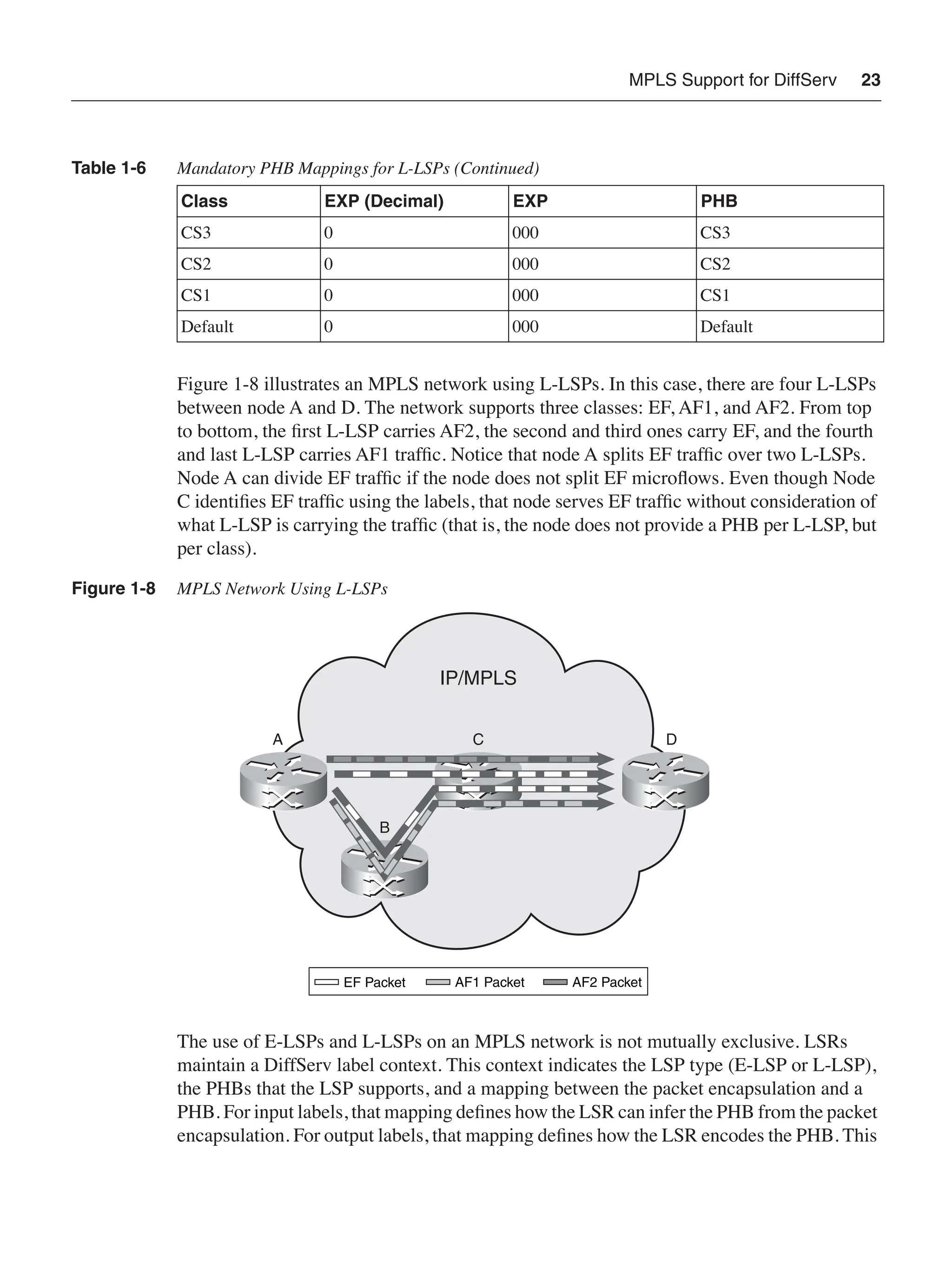
MPLS Support forDiffServ 23
Figure 1-8 illustrates an MPLS network using L-LSPs. In this case, there are four L-LSPs
between node A and D. The network supports three classes: EF, AF1, and AF2. From top
to bottom, the first L-LSP carries AF2, the second and third ones carry EF, and the fourth
and last L-LSP carries AF1 traffic. Notice that node A splits EF traffic over two L-LSPs.
Node A can divide EF traffic if the node does not split EF microflows. Even though Node
C identifies EF traffic using the labels, that node serves EF traffic without consideration of
what L-LSP is carrying the traffic (that is, the node does not provide a PHB per L-LSP, but
per class).
Figure 1-8 MPLS Network Using L-LSPs
The use of E-LSPs and L-LSPs on an MPLS network is not mutually exclusive. LSRs
maintain a DiffServ label context. This context indicates the LSP type (E-LSP or L-LSP),
the PHBs that the LSP supports, and a mapping between the packet encapsulation and a
PHB. For input labels, that mapping defines how the LSR can infer the PHB from the packet
encapsulation. For output labels, that mapping defines how the LSR encodes the PHB. This
Class EXP (Decimal) EXP PHB
CS3 0 000 CS3
CS2 0 000 CS2
CS1 0 000 CS1
Default 0 000 Default
Table 1-6 Mandatory PHB Mappings for L-LSPs (Continued)
IP/MPLS
C
B
D
A
EF Packet AF1 Packet AF2 Packet
44.
24 Chapter 1:QoS Technology Overview
context is populated with preconfigured mappings or through DiffServ information learned
during LSP setup. Table 1-7 compares E-LSPs and L-LSPs.
Figure 1-9 shows an MPLS network using L-LSPs and E-LSPs simultaneously. In this
example, there are two E-LSPs between node E and node D and two L-LSPs between node
A and D. The network supports three classes: EF, AF1, and AF2. In this example, node C
transports both E-LSPs and L-LSPs. This node uses the DiffServ label context to determine
the LSP type and the exact mapping that it should use to infer the PHB from the packet
encapsulation. LSRs serve the packets according to their PHB regardless of the LSP and its
type. The LSP details influence the PHB determination, but the PHB ultimately determines
the packet treatment. In this example, nodes A and E use one type of LSPs exclusively.
However, each of them could alternatively use a combination of E-LSPs and L-LSPs to
reach node D.
Figure 1-9 MPLS Network Combining L-LSPs and E-LSPs
Table 1-7 Comparing E-LSPs and L-LSPs
E-LSP L-LSP
One or more classes per LSP One class per LSP
PHB inferred from EXP field PHB inferred from Label and EXP field
Signaling optional Signaling required
IP/MPLS
C
B
D
A
E
EF Packet AF1 Packet AF2 Packet
E-LSP L-LSP
45.
MPLS Support forDiffServ 25
NOTE ATM LSRs, Frame Relays LSRs, and LSRs with LC-ATM interfaces do not forward
packets using an MPLS shim header encapsulation. The absence of a shim header implies
the absence of the EXP field. However, those devices can still support DiffServ using their
native encapsulation to implement L-LSPs.ATM LSRs and LSRs with LC-ATM interfaces use
the native label encoding and the ATM CLP (Cell Loss Priority) bit for PHB determination.
Frame Relay LSRs use their native label encoding and the Frame Relay DE bit for PHB
determination. RFC 3270 describes in detail the procedures that apply in those cases.
DiffServ Tunneling Models over MPLS
MPLS LSPs support for DiffServ defines three models of interaction between DiffServ
markings in different layers of encapsulation. A simple example is an IP packet that has
received the MPLS encapsulation. There is one PHB marking in the MPLS encapsulation
and a PHB marking in the DiffServ field of the IP packet. There are three models to handle
the interaction between multiple markings: the pipe, short-pipe, and uniform models. The
models define the procedures that an LSR can apply when a packet (either IP or MPLS)
with an existing PHB marking enters and exits an LSP. The three models do not introduce
any changes to the normal label swapping behavior of an LSR or any signaling
requirements. These models apply equally to E-LSPs and L-LSPs.
NOTE The MPLS DiffServ tunneling models extend the concepts introduced in RFC 2983. That
RFC defines the operation of DiffServ over IP tunnels. In many aspects, LSPs resemble IP
tunnels.
NOTE RFC 3270 defines the MPLS DiffServ tunneling models for the transport of IP and MPLS
traffic. However, the underlying concepts can apply to the transport of other types of traffic
(for example, Ethernet) over an MPLS network.
Pipe Model
The pipe model conceals the tunneled PHB marking between the LSP ingress and egress
nodes. This model guarantees that there are no changes to the tunneled PHB marking
through the LSP; even if an LSR along the path performs traffic conditioning and re-marks
the traffic. All LSRs that the LSP traverses use the LSP PHB marking and ignore the
tunneled PHB marking. This model proves useful when an MPLS network connects other
DiffServ domains. The MPLS network can implement DiffServ and still be transparent for
the connected domains. RFC 3270 defines this model as mandatory for MPLS networks
supporting DiffServ.
46.
26 Chapter 1:QoS Technology Overview
Figure 1-10 illustrates the operation of the pipe model. The LSP ingress determines the LSP
PHB marking it will encode in the pushed encapsulation. It may consider the existing PHB
marking of the packet for this purpose. It preserves the tunneled PHB marking when
pushing the new label encapsulation. Be aware that the packet entering the LSP may be an
IP or an MPLS packet. The LSP egress serves the packet according to the LSP PHB
marking. This action implies that this node infers the packet PHB before the pop operation.
Moreover, the LSP egress does not modify the tunneled PHB marking that the pop
operation exposes. An LSP using the pipe model cannot use penultimate hop popping
(PHP) because the LSP egress will not have access to the LSP PHB marking.
Figure 1-10 Pipe Tunneling Model
Short-Pipe Model
The short-pipe model represents a small variation of the pipe model. It also guarantees that
there are no changes to the tunneled PHB marking, even if an LSR re-marks the LSP PHB
marking. The short-pipe model shares the same ability of the pipe model to allow an MPLS
network to be transparent from the DiffServ point of view. The short-pipe model differs,
however, on how the LSP egress infers the packet PHB. The LSP egress uses the tunneled
PHB marking to infer the packet PHB and serve the packet consequently. Given this
difference with the pipe model, an MPLS network may implement LSPs using the short-
pipe model regardless of whether LSRs perform PHP.
Label Label
IP/MPLS
LSP
Ingress
LSP
Egress
LSP PHB
Marking
IP or MPLS
Packet
Tunneled PHB
Marking
Push Pop
LSP PHB Marking
Defines Packet PHB
47.
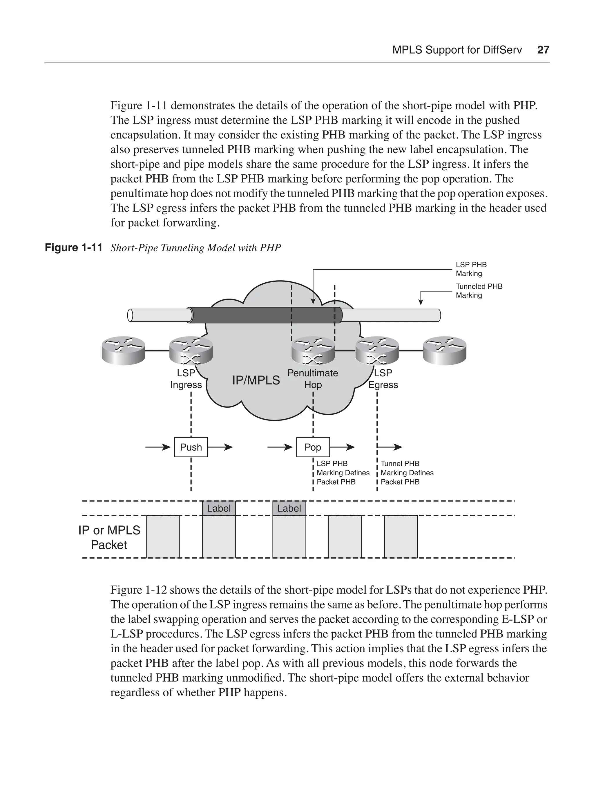
MPLS Support forDiffServ 27
Figure 1-11 demonstrates the details of the operation of the short-pipe model with PHP.
The LSP ingress must determine the LSP PHB marking it will encode in the pushed
encapsulation. It may consider the existing PHB marking of the packet. The LSP ingress
also preserves tunneled PHB marking when pushing the new label encapsulation. The
short-pipe and pipe models share the same procedure for the LSP ingress. It infers the
packet PHB from the LSP PHB marking before performing the pop operation. The
penultimate hop does not modify the tunneled PHB marking that the pop operation exposes.
The LSP egress infers the packet PHB from the tunneled PHB marking in the header used
for packet forwarding.
Figure 1-11 Short-Pipe Tunneling Model with PHP
Figure 1-12 shows the details of the short-pipe model for LSPs that do not experience PHP.
The operation of the LSP ingress remains the same as before. The penultimate hop performs
the label swapping operation and serves the packet according to the corresponding E-LSP or
L-LSP procedures. The LSP egress infers the packet PHB from the tunneled PHB marking
in the header used for packet forwarding. This action implies that the LSP egress infers the
packet PHB after the label pop. As with all previous models, this node forwards the
tunneled PHB marking unmodified. The short-pipe model offers the external behavior
regardless of whether PHP happens.
Label Label
IP/MPLS
LSP
Ingress
LSP
Egress
Penultimate
Hop
LSP PHB
Marking
IP or MPLS
Packet
Tunneled PHB
Marking
Push Pop
LSP PHB
Marking Defines
Packet PHB
Tunnel PHB
Marking Defines
Packet PHB
48.
28 Chapter 1:QoS Technology Overview
Figure 1-12 Short-Pipe Tunneling Model Without PHB
Uniform Model
The uniform model makes the LSP an extension of the DiffServ domain of the encapsulated
packet. In this model, a packet only has a single meaningful PHB marking (which resides
in the most recent encapsulation). LSRs propagate the packet PHB to the exposed encap-
sulation when they perform a pop operation. This propagation implies that any packet
re-marking is reflected on the packet marking when it leaves the LSP. The LSP becomes an
integral part of the DiffServ domain of the packet as opposed to the transparent transport
that the pipe and short-pipe models provided. This model proves useful when an MPLS
network connects other DiffServ domain and all networks (including the MPLS network)
need to behave as a single DiffServ domain.
Label Label
IP/MPLS
LSP
Ingress
LSP
Egress
LSP PHB
Marking
IP or MPLS
Packet
Tunneled PHB
Marking
Push Pop
Tunneled PHB Marking
Defines Packet PHB
49.
MPLS Support forDiffServ 29
Figure 1-13 illustrates the operation of the uniform model with PHP. The LSP ingress
encodes the existing packet PHB marking in the pushed encapsulation. When the packet
receives the new encapsulation, the encapsulated PHB marking becomes irrelevant. The
penultimate hop infers the packet PHB before the pop operation and encodes it in the
exposed encapsulation.
Figure 1-13 Uniform Tunneling Model with PHP
Figure 1-14 shows the details of the uniform model for LSPs without PHP. The operation
of the LSP ingress remains the same. The penultimate hop performs a regular label
swapping operation. The LSP egress always infers the PHB before the pop operation and
propagates the PHB marking to the exposed encapsulation. The uniform model offers the
same external behavior regardless of whether the LSP uses PHP. Tables 1-8 and 1-9
summarize the operation of the three tunneling modes with PHP and without PHP,
respectively.
Label Label
IP/MPLS
LSP
Ingress
LSP
Egress
Penultimate
Hop
LSP PHB
Marking
IP or MPLS
Packet
Push Pop
LSP PHB
Marking Defines
Packet PHB
(Propagated
Down)
50.
30 Chapter 1:QoS Technology Overview
Figure 1-14 Uniform Tunneling Model Without PHP
Table 1-8 DiffServ Tunneling Models over MPLS with PHP
Model LSP Ingress Penultimate Hop LSP Egress
Pipe Not possible. Not possible. Not possible.
Short-pipe Preserve tunneled PHB
and set PHB in pushed
encapsulation.
Determine PHB before
pop.
Determine PHB using
forwarding header.
Uniform Copy existing packet
PHB to pushed
encapsulation.
Determine PHB before
pop and propagate it
down.
Determine PHB using
received header.
Table 1-9 Tunneling Models over MPLS Without PHP
Model LSP Ingress LSP Egress
Pipe Preserve tunneled PHB and set PHB in
pushed encapsulation.
Determine PHB before pop operations.
Short-pipe Preserve tunneled PHB and set PHB in
pushed encapsulation.
Determine PHB after pop using
forwarding header.
Uniform Copy existing packet PHB to pushed
encapsulation.
Determine PHB before pop
and propagate it down.
Label Label
IP/MPLS
LSP
Ingress
LSP
Egress
LSP PHB
Marking
IP or MPLS
Packet
Push Pop
LSP PHB Marking
Defines Packet PHB
(Propagated Down)
51.
Traffic-Management Mechanisms 31
Traffic-ManagementMechanisms
The implementation of QoS ultimately relies on a collection of traffic-management
mechanisms. The evolution of packet switched networks introduced the need for the
development of suitable traffic-management mechanisms. These mechanisms help network
nodes avoid and manage congestion. Frame Relay and, especially,ATM networks make use
of some of these or similar techniques. This section summarizes the key concepts behind
traffic management within the context of IP and MPLS networks. These mechanisms
represent the building blocks that network nodes use to implement QoS using both the
DiffServ and IntServ architectures.
Traffic Classification
Network nodes generally perform traffic classification before applying traffic-management
mechanisms. The aggregate traffic that traverses a node typically combines traffic with
different QoS requirements. In those cases, network nodes need to classify the traffic to
provide the expected level of differentiation.
Traffic classification can be in the form of an MF or BA classifier in the context of DiffServ.
Classification can also be in the form of filter specification in IntServ. Traffic classification
typically involves stateless inspection of packet headers. In some cases, nodes perform
packet payload inspection or even stateful inspection of packets. However, the complexity
and processing impact of those two types of classification limits its applicability to
particular devices in the network.
Traffic Marking
Packet marking involves assigning a new value to a QoS-related field in the header of a
packet. This marking typically associates the packet with a class or a drop precedence. As
discussed earlier, the DiffServ architecture relies on packet marking to indicate the PHB for
each packet. Several Layer 2 technologies also make use of packet marking for QoS
purposes, as follows:
• Ethernet uses a 3-bit priority field in the VLAN header.
• ATM uses a 1-bit field to indicate the drop precedence of a cell (cell loss priority or
CLP).
• Frame Relay uses an equivalent 1-bit field to capture the drop precedence of a frame
(Discard Eligible or DE).
yellow. S. anemonæflòrais of various colours, and very similar to
Anemòne.
Tritònia, a genus of about twenty-five species. Few of them
deserve culture in regard to their beauty. T. crocàta is in our
collections, as I. crocàta, which is amongst the finest, and T.
zanthospìla has white flowers curiously spotted with yellow.
Watsònia, a genus containing several species of showy flowers,
several of which are in our collections, under the genus Gladíolus,
but the most of the species may easily be distinguished from it by
their flat shell formed bulbs. W. iridifòlia is the largest of the genus,
and has flowers of a flesh colour. W. ròsea is large growing, the
flowers are pink, and on the stem in a pyramid form. W. humilis is a
pretty red flowering species. W. fúlgida, once Antholyza fúlgens, has
fine bright scarlet flowers. W. rùbens is an esteemed red flowering
species, but scarce.
These six genera are in general cultivation. There are several of
others of merit that our limits will not admit of inserting. We have no
doubt there are some splendid species that have not come under
our observation, and others which may be obtained from the Cape
of Good Hope not known in any collection. Many hundreds of superb
bulbs indigenous to that country, and of the same nature and habit
of the above, have not been seen in collections. The flowers of those
which we have specified are from one to four inches in diameter,
ringent, tubular, or campanulate. Pots from four to seven inches
diameter, according to the size of the roots, will be large enough.
Give them very little water until they begin to grow; then supply
moderately, and keep them near the light. Of the Holland or Dutch
bulbs, the Hyacinth is the favourite to bloom in the Green-house. A
few of the Tulip, Narcissus, Iris, and Crocus, may for variety be also
planted with any other that curiosity may dictate. When these are
grown in pots, the soil should be four-eighths loam, two-eighths leaf
mould, one-eighth decomposed manure, one-eighth sand, well
compounded; plant in pots from four to seven inches, keep the
crown of the bulb above the surface of the soil, except of the Tulip,
54.
which should becovered two inches. When these roots are potted,
plunge them in the garden about three inches under ground; mark
out a space sufficient to contain them; throw out the earth about
four inches deep, place the pots therein, covering them with earth to
the above depth, making it in the form of a bed. Leave a trench all
round to carry off the rain. By so doing, the bulbs will root strong,
the soil will be kept in a congenial state about them, and they will
prove far superior than if done in the common method. Lift them
from this bed on the approach of frost, or not later than the second
week of December, wash the pots and take them to the Green-
house.
OF REPOTTING.
Vibúrnum. This is a good period to repot all the flowering plants
of this genus. For a full description of them, see Green-house,
March. The repotting is only intended for young plants that are
wanted to grow freely. When the V. tìnus is much encouraged, it
does not flower profusely.
Lìlium, Lily. There are four species of this splendid genus kept in
the Green-house. It has always been our practice to repot them
when they begin to grow, though it is said by some that, when
removed at that time, they will not flower perfectly. They will not do
to be kept above a few weeks out of the ground, and we think they
ought never to be kept out any period. We place them here, that a
choice may be made by the cultivator of either of the periods, which
is not material; observing in either case, that excess of moisture is
injurious while they are dormant. L. longiflòrum grows about one
foot high, with one or more flowers. L. longiflòrum suavèolens, is
sweet-scented, and has only one flower. L. japònicum is the most
magnificent, grows about two feet high, with three or more flowers
on one stem. L. lancifòlium; we incline to class this with L.
speciòsum, there being no apparent distinction in any character. The
flowers are all of the purest white. They require from five to seven
inch pots.
56.
Flower Garden.
SEPTEMBER.
OF DAHLIAS.
Seethat all these plants are supported with proper stakes, rods,
&c., that the wind may have no effect in breaking down or otherwise
destroying the flower stems. Strictly observe their respective heights
and colours, that they may be duly disposed and interspersed next
year, if not done so this. If the early part of the month is dry, give
them liberal supplies of water.
GENERAL CARE OF PLANTS IN POTS.
All the flowers that are in pots, and intended to be kept in frames
during winter, should have a top-dressing, and a general preparation
for their winter quarters, by tieing up, &c. The carnation and pink
layers that were lifted and potted last month must be brought from
the shade as soon as they begin to grow; and those that are not
lifted, have them done forthwith, that they may be rooted afresh
before the frost sets in. All Wall-flowers and Stocks should be lifted
this month, and planted in five to seven inch pots, and treated as
directed for carnation layers last month, until they begin to grow,
when they must be fully exposed.
PREPARE BEDS AND BORDERS FOR BULBOUS ROOTS.
Bulbous roots of every character delight in deep free soil;
consequently, wherever they are desired to be planted, due attention
must be paid to put the soil in proper order, to have them in
57.
perfection. Where thereare a quantity intended to be planted, to
have them in beds is the general and preferable method. These
ought to be dug from eighteen inches to two feet deep, at the
bottom of which place three or four inches of decayed manure.
Where the soil is poor it should be enriched with well decomposed
manure and earth from the woods, incorporating both well with the
soil, breaking it all fine. This being done, allow it to stand until the
middle of next month, which see for farther directions.
GENERAL OBSERVATIONS.
Tie up carefully all the Chrysánthemums, Tuberoses, &c. Clear
away the stems or haulm of any decayed annuals or herbaceous
plants, that nothing unsightly may appear. Be attentive to the
collecting of all kinds of seeds.
58.
Rooms.
SEPTEMBER.
Where there isa quantity of plants to be kept in these
apartments, they should be disposed to the best effect, and at the
same time in such a manner as will be most effectual to their
preservation. A stage of some description is certainly the best, and,
of whatever shape or form, it ought to be on castors, that it may, in
severe nights of frost, be drawn to the centre of the room. The
shape may be either concave, a half circle, or one square side. The
bottom step or table should be six inches apart, keeping each
successive step one inch farther apart, to the desired height, which
may be about six feet. Allowing the first step to be about two feet
from the floor, there will be five or six steps, which will hold about
fifty pots of a common size. A stage in the form of half a circle will
hold more, look the handsomest, and be most convenient. We have
seen them circular, and when filled appeared like a pyramid. These
do very well, but they must be turned every day, or the plants will
not grow regularly. With this attention it is decidedly the best. Green
is the most suitable colour to paint them.
GENERAL OBSERVATIONS.
The directions given for the Green-house this month are equally
applicable here. The Tasseled White Chrysanthemum, and a few
other late blooming sorts, are particularly adapted for rooms. If
there is no convenience to plunge the pots with Dutch bulbs in the
garden, as described in the Green-house of this month, give them
very little water until they begin to grow.
60.
Hot-House.
OCTOBER.
Very few directionsremain to be given to the department of the
Hot-house. The supplies of water for this and the two preceding
months are, according to the state and nature of tropical plants,
more limited than at any other period of the year. This is the first
month of what may be called their dormant state. Observe the
herbaceous plants, that they are, as soon as their foliage decays, set
aside, in case of being too liberally supplied with water. Airing is
highly essential about this period, that the plants may be gradually
hardened; but guard against injuring them. The temperature should
not be under fifty degrees; when the days are cool, and the wind
chilling, airing is not necessary; and when air is admitted, always
close up early in the afternoon, whilst the atmosphere is warm, to
supersede the necessity of fire as long as possible. If at any time
you have recourse to it in this month, use it with great caution.
Examine all the shutters and fastenings, and see that they are in
good substantial order, and where deficient repair them instantly,
that they may be in readiness. Remove all leaves, and give
syringings twice a week. Clear off, sweep out, and wash clean, that
every part may be in the neatest order.
61.
Green-House.
OCTOBER.
OF TAKING INAND ARRANGING THE PLANTS.
As observed in the previous month, let the housing of Green-
house plants now be attended to. Have all in before the eighth of
the month, except a few of the half hardy sorts, which may stand
until convenient. Begin by taking in all the tallest first, such as
Oranges, Lemons, Myrtles, Oleanders, &c. Limes ought to be kept in
the warmest part of the house, otherwise they will throw their
foliage. In arrangement, order is necessary to have a good effect;
and in small houses it ought to be neat and regular, placing the
tallest behind, and according to their size graduating the others
down to the lowest in front. Dispose the different sorts in varied
order over the house, making the contrast as striking as possible.
Having the surface of the whole as even as practicable, with a few of
the most conspicuous for shape and beauty protruding above the
mass, which will much improve the general appearance, and greatly
add to the effect. All succulents should be put together. They will do
in a dark part of the house, where other plants would not grow,
studying to have the most tender kinds in the warmest part, and
giving gentle waterings every three or four weeks. When all are
arranged, give them a proper syringing, after which wipe clean all
the stages, benches, &c. sweeping out all litter, and wash clean the
pavement, which will give to all a neat and becoming appearance.
Let the waterings now be done in the mornings, as often and in
such quantities as will supply their respective wants, examining the
plants every day.
62.
During the continuanceof mild weather, the circulation of air
must be as free as possible, opening the doors and front and top
sashes regularly over the house. But observe in frosty nights, and
wet, cloudy weather, to keep all close shut. Be attentive in clearing
off decayed leaves and insects.
Any plants of Lagerstræmia, Stercùlia, Hydrángea, Pomegranate,
and others equally hardy, that are deciduous, may be kept perfectly
in a dry, light, airy cellar, giving frequent admissions of air.
OF REPOTTING.
Anemònes. Where A. nemoròsa flòre plèno and A. thalictròides
flòre plèno are kept in pots in the Green-house, they should be
turned out of the old earth, and planted in fresh soil. They are both
pretty, low growing, double white flowering plants, and require a
shaded situation. The latter is now called Thalíctrum anemonoídes.
Dáphne, is a genus of diminutive shrubs, mostly evergreens, of
great beauty and fragrance. Very few species of them are in our
collections. D. odòra, frequently called D. índica, is an esteemed
plant for the delightful odour of its flowers, and valuable for the
period of its flowering, being from December to March, according to
the situation; leaves scattered, oblong, lanceolate, smooth; flowers
small, white, in many-flowered terminale heads. D. hybrida is a
species in high estimation at present in Europe, but little known
here, being only in a few collections; flowers rose-coloured, in
terminale heads, and lateral bunches in great profusion, and very
similar to the former in habit and shape of flower; blooms from
January to May, and is of a peculiar fragrance. D. oleoídes is what
may be termed "ever-blooming;" flowers of a lilac colour; leaves
elliptic, lanceolate, smooth. D. laurèola, Spurge laurel; D. póntica, D.
alpìna, and D. Cneòrum, are all fine species, and in Europe are
esteemed ornaments in the shrubbery, but we are not certain if they
will prove hardy in our vicinity.
63.
Prímula. There area few fine species and varieties in this genus,
adapted either for the Green-house or Rooms. All the species and
varieties will keep perfectly well in a frame, except the China sorts.
Having previously observed a few of the other species and varieties,
we will observe the treatment of these. P. sinénsis, now prænitens,
known commonly as China Primrose; flowers pink, and in large
proliferous umbels, flowering almost through the whole year, but
most profusely from January to May. Keep them in the shade, and
be careful that they are not over-watered during summer. As the
stems of the plant become naked, at this repotting a few inches
should be taken off the bottom of the ball, and placing them in a
larger pot will allow the stems to be covered up to the leaves. P. p.
albiflòra, colour pure white and beautiful. P. p. dentiflòra. There is
also a white variety of this, both similar to the two former, only the
flower indented. All these require the same treatment. As they only
live a few years, many individuals, to propagate them, divide the
stems, which in most cases will utterly destroy them. The best, and
we may say the only method to increase them, is from seed, which
they produce in abundance every year.
Pæonia, is a magnificent genus. There are four varieties of them,
half hardy and half shrubby. They will bear the winter if well
protected, but are better in the Green-house. These are P. moután,
Tree Pæony; the flower is about four inches in diameter, of a blush
colour, and semi-double; P. M. Bànksii is the common Tree Pæony,
and called in our collection P. Moutàn; it has a very large double
blush flower, and is much admired. P. M. papaveràcea is a most
magnificent variety; has large double white flowers, with pink
centres; P. M. ròsea is a splendid rose-coloured double variety, and is
scarce. These plants ought not to be exposed to the sun while in
flower, as the colours become degenerated, and premature decay
follows.
If the Dutch bulbs intended for flowering during winter are not
potted, have them all done as soon as possible, according to
directions given last month.
64.
CAMELLIAS.
These plants oughtto have a thorough examination, and those
that were omitted in repotting before they commenced growing,
may be done in the early part of this month; but it is not adviseable,
except the roots are matted round the ball of earth, which should be
turned out entire. Examine all the pots, stir up the surface of the
earth, and take it out to the roots, supplying its place with fresh soil.
Destroy any worms that may be in the pots, as they are very
destructive to the fibres. Look over the foliage and with a sponge
and water clear it of all dust, &c. Frequently the buds are too
crowded on these plants, especially the Double white and
Variegated. In such case pick off the weakest, and where there are
two together, be careful in cutting, so that the remaining bud may
not be injured.
This is the best period of the year to make selections of these, as
they now can be transported hundreds of miles without any material
injury, if they are judiciously packed in close boxes. In making a
choice of these, keep in view to have distinctly marked varieties,
including a few of those that are esteemed as stocks for producing
new kinds, which are undoubtedly indispensable; and will reward the
cultivator in a few years with new sorts. Besides, it will afford
unbounded gratification to behold any of these universally admired
ornaments of the Green-house improving by our assistance and
under our immediate observation. There is nothing to prevent any
individual from producing splendid varieties in a few years. Mr. Hogg
correctly observes, "It is very probable in a few years we shall have
as great a variety of Camellias, as there are of Tulips, Hyacinths,
Carnations, Auriculas, &c."
It has been often said that these plants are difficult of cultivation.
This is unfounded, indeed they are the reverse if put in a soil
congenial to their nature. When highly manured soils are given,
which are poisonous to the plants, sickness or death will inevitably
ensue; but this cannot be attributed to the delicacy of their nature.
We can unhesitatingly say there is no Green-house plant more hardy
65.
or easier ofcultivation, and they are equally so in the parlour, if not
kept confined in a room where there is a continuance of drying fire
heat, their constitution not agreeing with an arid atmosphere.
66.
Flower-Garden.
OCTOBER.
OF PLANTING VARIOUSBULBOUS FLOWER ROOTS.
From the middle of October to the beginning of November is the
best period for a general planting of Dutch bulbs.
Cròcuses are the earliest in flower, and may be planted about six
inches off the edgings, about four inches apart and two deep, or in
beds four feet wide; the varieties selected and planted across the
bed in rows of distinct colours, they flowering so early, and in that
manner have a grand effect. There are above sixty varieties to be
had.
Hyacinths. The ground that was prepared for these last month,
should be all divided into beds four feet wide, leaving between each
alleys of twenty inches. Skim off three inches of the surface of the
former into the latter, level the bed smoothly with the rake, and
mark it off in rows eight inches apart. Plant the roots in the row
eight inches asunder. Thus they will be squares of eight inches, and
by planting the different colours alternately the bed will be
beautifully diversified. Press each root gently down with the hand,
that in covering up they may not be displaced. Put about four inches
of earth over the crowns, which will make the beds from two to
three inches higher than the alleys. The beds before and after
planting should be gently rounded from the middle to each side to
let the rain pass off. Finish all by raking evenly, straighten the
edgings with the line, and clear out the alleys or pathways.
Tulips like a lighter and richer earth than Hyacinths. Prepare the
beds in the same manner, and so as the roots will stand nine inches
67.
apart each way;cover them five inches deep, as the new bulbs are
produced above the old.
If it is intended to screen either of these while in flower, the beds
should be made wider. Where two beds are to be shaded under one
awning, make the alleys alternately two or three feet wide; the one
two feet wide to be under the awning.
Polyanthus and Italian Narcissus, may be planted in every respect
as Hyacinths, only they require a lighter and richer soil.
Jonquils. Plant these in the same soil as Tulips, six inches apart,
and cover three inches deep. They do not flower so well the first
year as in the second and third, therefore should only be lifted every
third year.
Anemones and Ranunculuses. These roots like a fresh rich, well
pulverized, loamy soil. In light sandy soils they will languish in early
droughts, and sometimes do not show their flowers fully. Cow
manure is the best to use for enriching the soil. The whole should be
well mixed and incorporated to the depth of eighteen or twenty
inches. The roots may be planted in four-foot beds, or in such a
manner as a low frame of boards can be placed over them, when
the winter sets in very severe. If intended to be shaded while in
flower, leave a sufficiency of space in the alleys as directed for Tulips
and Hyacinths. Do not raise the beds above one inch higher than the
alleys, and form the surface level, in order to detain rather than
throw off moisture. Then draw drills exactly two inches deep and six
inches apart across the bed. In these place the roots, claws down,
about four inches distant from each other. The roots of the
Anemones are flat, and the side on which there are small
protuberances, is that from which the stems proceed. Press each
root a little down with the hand, and cover all carefully so as not to
displace them. Smooth the surface with the rake, leaving the bed
quite level.
Many other bulbous flowers might be added to the above; but as
their culture is so similar, it would be superfluous to say more of
68.
them. They shouldbe allowed space and depth according to the size
of the bulb; a covering of two inches for the smallest, and five for
the largest, will generally answer, and the intermediate roots in
proportion. We will enumerate a few of the different kinds, Starch
and Musk Hyacinths; of Narcissus, the Paper, Grand Monarque, and
Nodding, with the two previously mentioned, are the most profuse in
flower. Some of them will have above twelve flowers on one stem.
Of Lilies, all the varieties of Mártagon, Tigrìnum and Chalcedónicum,
with our native species and varieties. Of Iris, Lusitánica, two
varieties, yellow and blue; Xiphioídes, or Ziphioídes; and Pérsica, are
the finest of the bulbous sorts. Snow-drop with several other minor
bulbs.
All of these flowering bulbs may be advantageously planted in
patches through the garden by taking out about one square foot of
earth. Break it well, and if poor enrich it. Plant four bulbs in each of
the same colour, and the clumps that are contiguous to contain
different colours.
PLANTING AND TRANSPLANTING.
This is a very proper period to plant the beautiful and early
flowering Pyrus japónica, now called Cydónia japónica. The blossoms
are of a rich scarlet colour. It is the earliest flowering shrub of the
garden, and deciduous, though said by some to be "an evergreen."
The plant is bushy, and well adapted for single plants in grass plats,
or forming low ornamental hedges. There is likewise C. j. álba, a fine
white variety of the same habit, and both are of the hardiest nature
—also for the various species of Anemònes and all the herbaceous
Pæonias.
Of the latter there are above nineteen species and twenty-two
varieties, a few of which are particularly esteemed, and exceedingly
handsome. P. èdulis whitlíji is a splendid large double P èdulis white;
P. Hùmei is a beautiful large double dark blush; P. èdulis fràgrans is a
fine large double scarlet, rose-scented variety. These three plants
69.
ought to bein every garden. The flowers are full in the centre, and
frequently above six inches in diameter; P. álba chinènsis is said to
be the largest and finest of the herbaceous sorts; colour pure white,
with pink at the bottom of the petals—it is a scarce variety; P.
paradóxa fimbàtria, fringed double red, and esteemed; P. officinális
rúbra is the common double red. There are several other very fine
single species and varieties, the flowers of which are principally red
or blush, but none so magnificent as the above mentioned. This is
perhaps a more favourable period to plant Dodecátheon than March;
for its character see that month of this department. Asclèpias
tuberòsa should now be planted.
Double Primroses, Polyanthus, Daisies, &c. Any of these that
were planted in shaded situations in spring, and have been
preserved through the summer, should have for their farther
protection a bed well sheltered from the north west, in which they
should be planted four inches apart. Give them a few sprinklings of
water in the morning, and have a temporary frame of rough boards
put together to place over them during the severity of winter. The
frame may be covered with the same in place of glass, which must
be kept over them while they are in a frozen state.
Any other plants that are in the ground, which are intended to be
protected with frames through the winter, ought to be immediately
lifted and potted; and treated as directed for all new potted plants.
GRASS AND GRAVEL WALKS.
The former should be trimly cut and well rolled this month, that
they may appear neat all winter. Never allow decayed leaves to lay
any time upon them, as they are apt to rot out the grass. The latter
should be divested of every weed, and receive a firm rolling. Clear
them at all times of leaves and other litter. These, if on a declivity,
and have not a firm substantial bottom, will be subject to be cut up
with every heavy rain. A break should be put in every twenty, forty,
70.
or eighty feet,to throw off the water. A strong plank will answer
perfectly well, but in such situations we would prefer grass-walks.
PLANTING EVERGREENS.
This month is the best period in autumn to plant these shrubs,
and where there is a great extent to be planted it would be
advisable to do a part of it now; but we give the preference to April,
which see for directions.
GENERAL OBSERVATIONS.
When the plantings of bulbs, &c. are finished, every part of the
garden should have a thorough cleaning. All annual flowers will have
passed the season of their beauty; therefore, remove the decayed
flower stems or haulm, and trim off the borders. Dig all vacant
ground, especially that intended to be planted with shrubs in the
ensuing spring, which ought to be dug from one to two feet deep.
Roses delight in a deep light soil.
71.
Rooms.
OCTOBER.
Have a stageor stages, as described last month, in the situations
where they are intended to remain all winter; place the plants on
them from the first to the eighth of this month, beginning with the
tallest on the top, graduating to the bottom. It is desirable to place
flats or saucers under each, to prevent the water from falling to the
floor, and the water should be emptied from the flats of all except
those of Cálla and Hydrángea. The latter while dormant should be
kept only a little moist.
Previous to taking in the plants, they should be divested of every
decayed leaf, insects, and all contracted dust, having their shoots
neatly tied up, and every one in correct order. Every leaf of the
Caméllias ought to be sponged, and the plants placed in a cool airy
exposure, shaded from the direct rays of the sun. If the flower buds
are too crowded, picking off the weakest will preserve the remainder
in greater perfection, and prevent them in part from falling off. Do
not on any occasion keep them in a room where there is much fire
heat, as the flower buds will not expand in an arid atmosphere. See
Green-house this month more largely on this subject.
OF BULBOUS ROOTS.
Those that are intended to flower in glasses, should be placed
therein this month and kept in a cool room. After the fibres begin to
push a few shoots, the glasses may be taken to the warmest
apartments to cause them to flower early. Bring a few from the
coldest to the warmest every two weeks, and thus a succession of
bloom may be kept up from January to March. Where the roots
72.
intended for potsare still out of the ground, the sooner they are
planted the better. (See last month for directions.)
Cape Bulbs. All that are unplanted and offering to grow, should
be put in pots forthwith. Ample directions are given for the planting
of these in the two preceding months.
Repot Rùbus rosæfòlius, or Bramble-rose. They should have pots
one size larger than those they are now in. To make them flower
profusely, when done blooming in May, divide them and put only a
few stems in one pot, and repot them in this month, as above
directed.
GENERAL OBSERVATIONS.
Any herbaceous plants in the collection ought to be set aside,
and the water in part withheld. When the stems and foliage are
decayed, the plants may be put in a cool cellar, where they will not
be in danger of frost, and be permitted to remain there until they
begin to grow; then bring them to the light, and treat as directed for
these kinds of plants. Deciduous plants may be treated in a similar
manner.
73.
Welcome to ourwebsite – the perfect destination for book lovers and
knowledge seekers. We believe that every book holds a new world,
offering opportunities for learning, discovery, and personal growth.
That’s why we are dedicated to bringing you a diverse collection of
books, ranging from classic literature and specialized publications to
self-development guides and children's books.
More than just a book-buying platform, we strive to be a bridge
connecting you with timeless cultural and intellectual values. With an
elegant, user-friendly interface and a smart search system, you can
quickly find the books that best suit your interests. Additionally,
our special promotions and home delivery services help you save time
and fully enjoy the joy of reading.
Join us on a journey of knowledge exploration, passion nurturing, and
personal growth every day!
ebookbell.com


![xiv
Icons Used in This Book
Command Syntax Conventions
The conventions used to present command syntax in this book are the same conventions used in the IOS
Command Reference. The Command Reference describes these conventions as follows:
• Boldface indicates commands and keywords that are entered literally as shown. In actual
configuration examples and output (not general command syntax), boldface indicates commands
that are manually input by the user (such as a show command).
• Italics indicate arguments for which you supply actual values.
• Vertical bars (|) separate alternative, mutually exclusive elements. Note, however, that the vertical
bar (pipe operand) is also used to filter command-line interface command output; in that scenario,
the operand (|) precedes the begin, exclude, or include keywords, which are then followed by a
regular expression.
• Square brackets [ ] indicate optional elements.
• Braces { } indicate a required choice.
• Braces within brackets [{ }] indicate a required choice within an optional element.
PC PC with
Software
Sun
Workstation
Macintosh
Terminal File
Server
Web
Server
Cisco Works
Workstation
Printer Laptop IBM
Mainframe
Front End
Processor
Cluster
Controller
Modem
DSU/CSU
Router Bridge Hub DSU/CSU Catalyst
Switch
Multilayer
Switch
ATM
Switch
ISDN/Frame Relay
Switch
Communication
Server
Gateway
Access
Server
Network Cloud
Token
Ring
Token Ring
Line: Ethernet
FDDI
FDDI
Line: Serial Line: Switched Serial](https://image.slidesharecdn.com/11004502-250519054220-aad40b60/75/Qos-For-Ipmpls-Networks-Gallo-Mark-Zhang-Raymond-Alvarez-Santiago-16-2048.jpg)


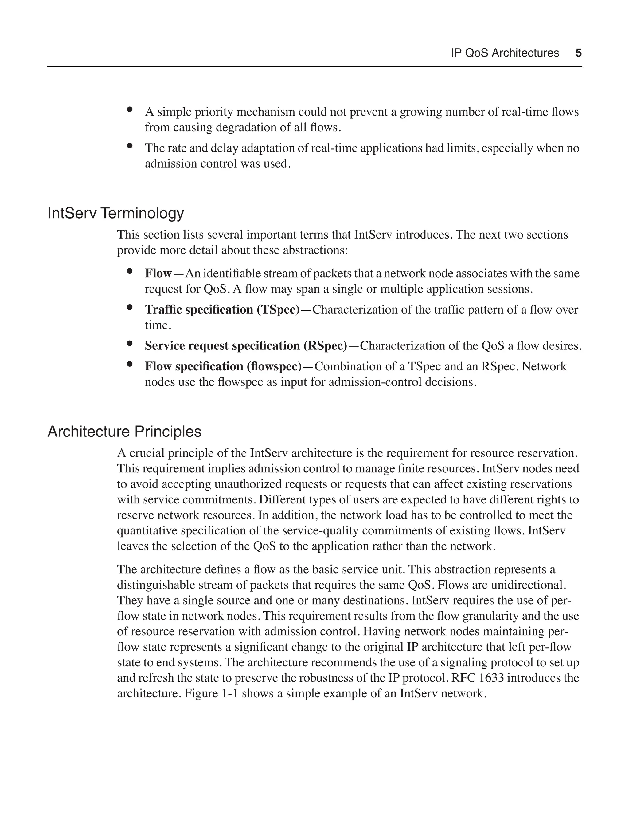

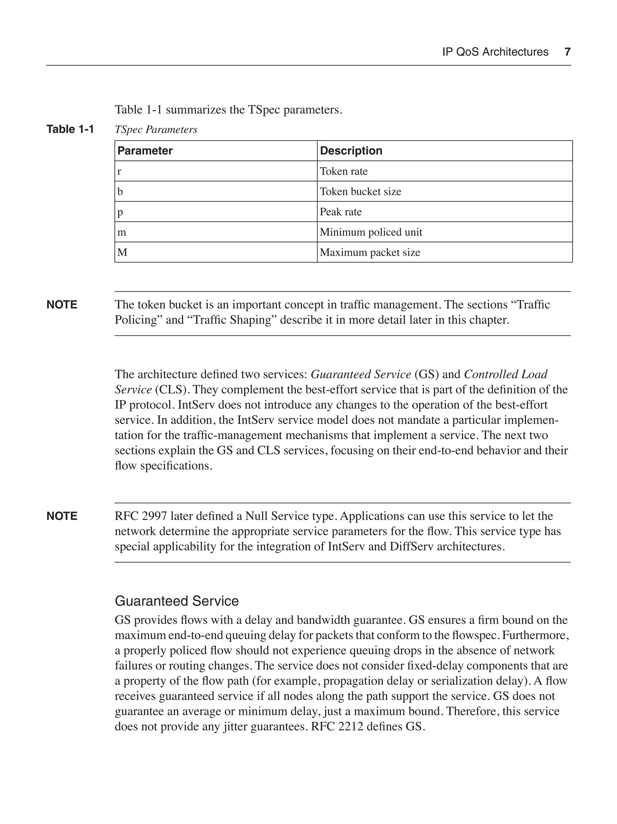

![IP QoS Architectures 9
Differentiated Services
The DiffServ working group was responsible for the definition of this architecture at the
IETF. The group met for the first time during the forty-first IETF in 1998. The working
group was created with a charter to produce an architecture with a simple and coarse QoS
approach that applied to both IPv4 and IPv6. The charter explicitly excluded microflow
identification and signaling mechanisms (marking an explicit departure from the approach
taken by IntServ). The working group produced 12 RFCs, with five of them being in the
standards track and the rest being informational. The group eventually closed after its last
meeting in 2001.
NOTE An IP traffic stream with a unique combination of source address, destination address,
protocol, source port, and destination port defines a microflow.
DiffServ Terminology
The DiffServ architecture introduces many new terms. This section presents a simplified
definition of a selected few of them. The upcoming sections explain the terms in more
detail. RFC 2475 and 3260 introduce the complete list of terms:
• Domain—A network with a common DiffServ implementation (usually under the
same administrative control).
• Region—A group of contiguous DiffServ domains.
• Egress node—Last node traversed by a packet before leaving a DiffServ domain.
• Ingress node—First node traversed by a packet when entering a DiffServ domain.
• Interior node—Node in a DiffServ domain that is not an egress or ingress node.
• DiffServ field—Header field where packets carry their DiffServ marking. This field
corresponds to the six most significant bits of the second byte in the IP header
(formerly, IPv4 TOS [Type-of-Service] octet and IPv6 Traffic Class octet).
• Differentiated Services Code Point (DSCP)—A specific value assigned to the
DiffServ field.
• Behavior aggregate (BA)—Collection of packets traversing a DiffServ node with the
same DSCP.
• Ordered aggregate (OA)—A set of BAs for which a DiffServ node must guarantee
not to reorder packets.
• BA classifier—Classifier that selects packets based on DSCP.
• Multifield (MF) classifier—Classifier that selects a packet based on multiple fields
in the packet header (for example, source address, destination address, protocol, and
protocol port).](https://image.slidesharecdn.com/11004502-250519054220-aad40b60/75/Qos-For-Ipmpls-Networks-Gallo-Mark-Zhang-Raymond-Alvarez-Santiago-29-2048.jpg)
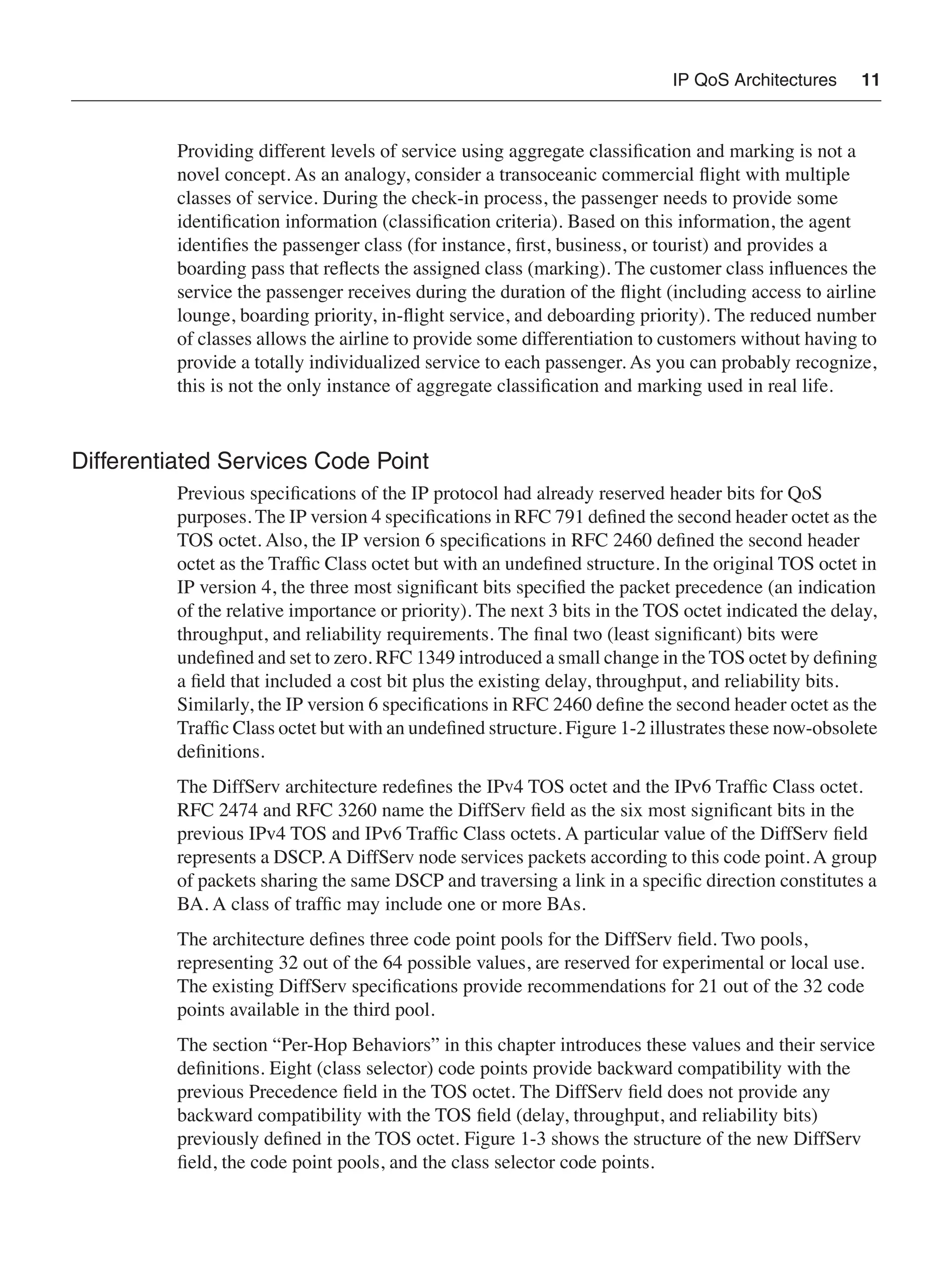

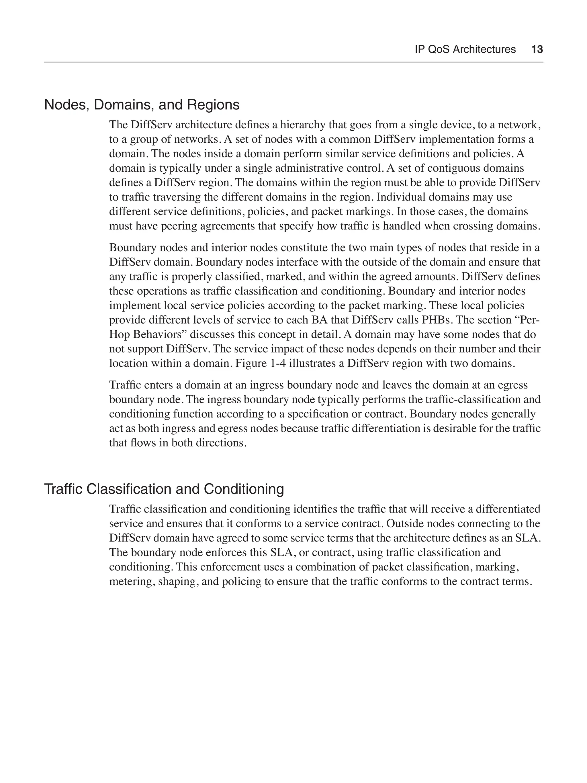


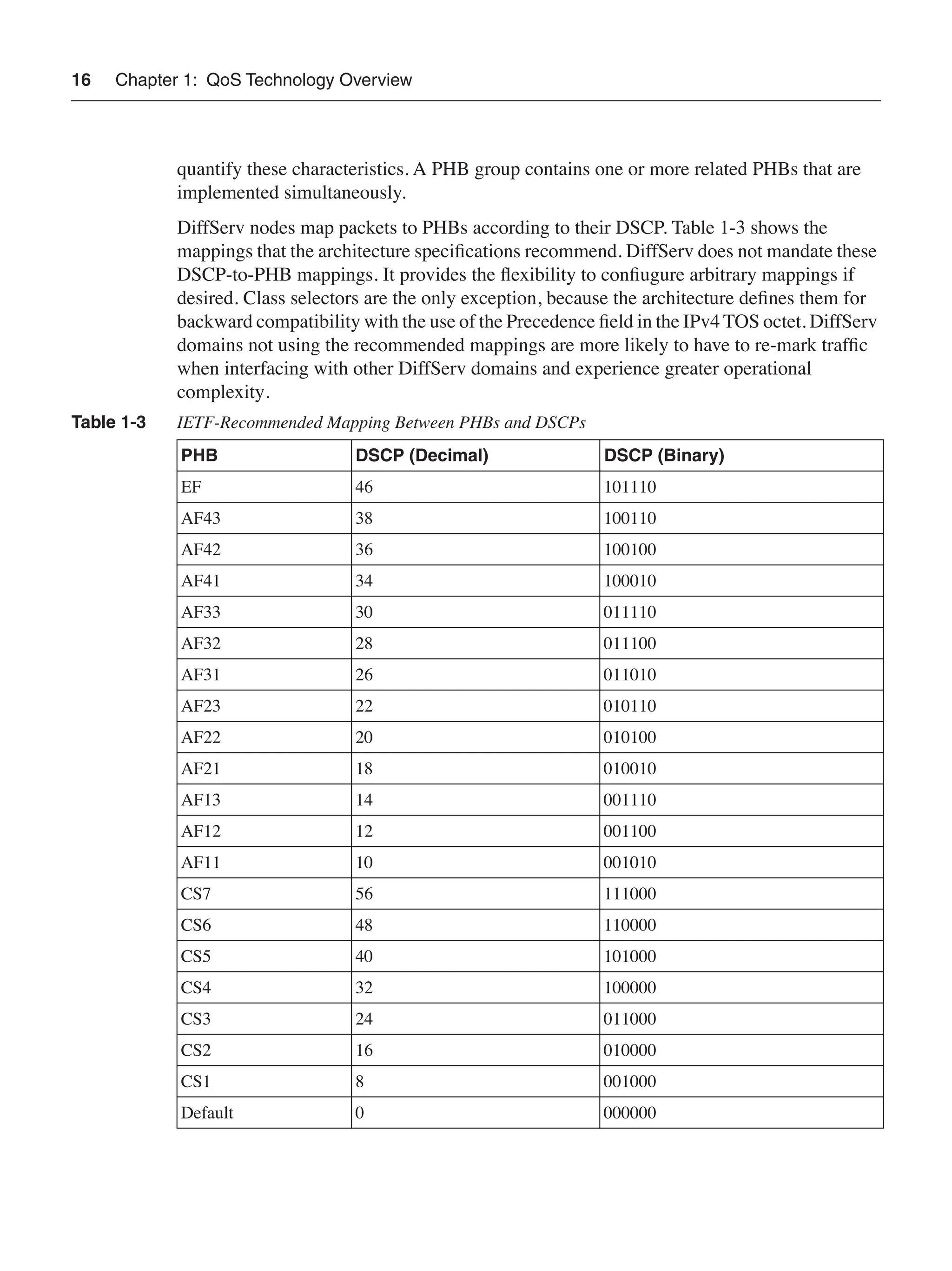
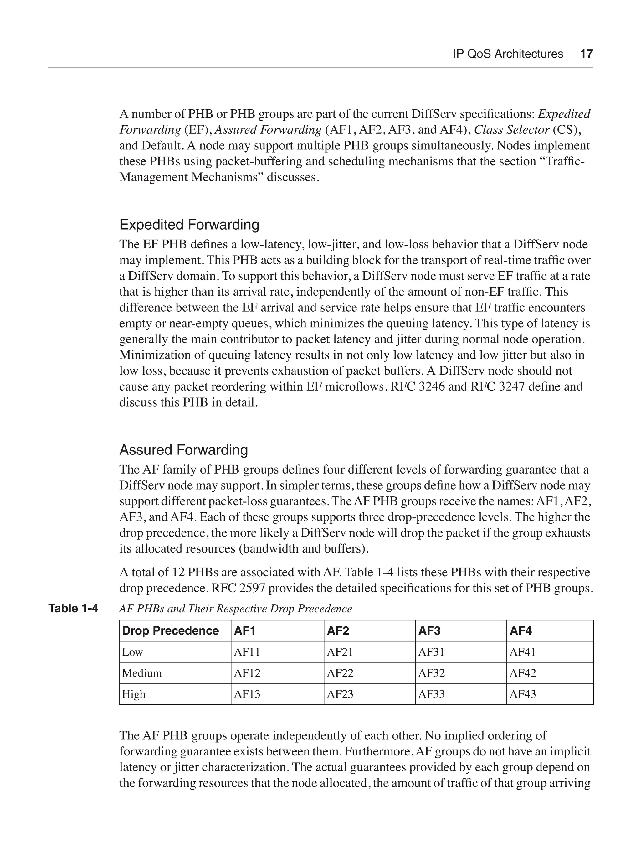

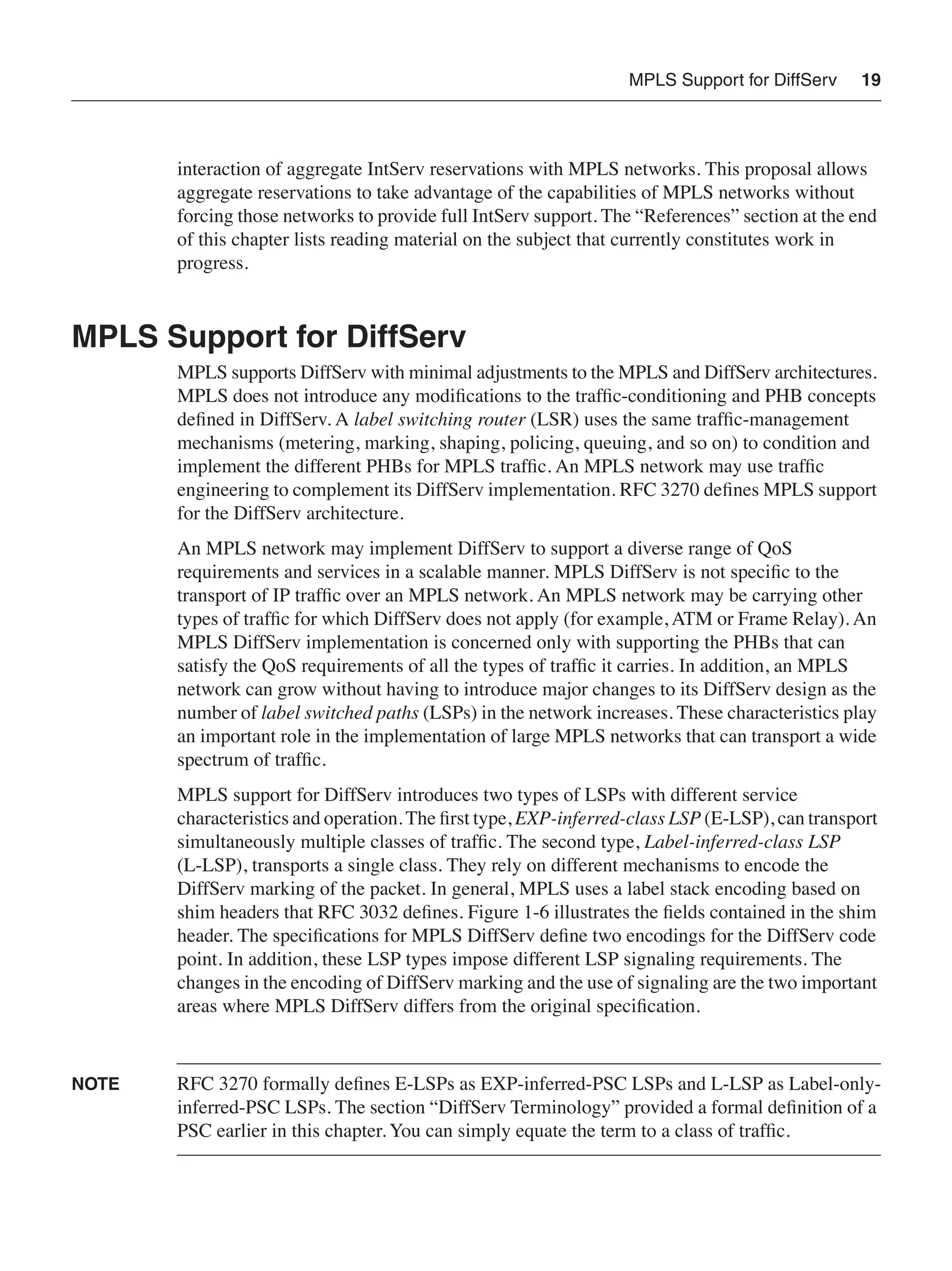
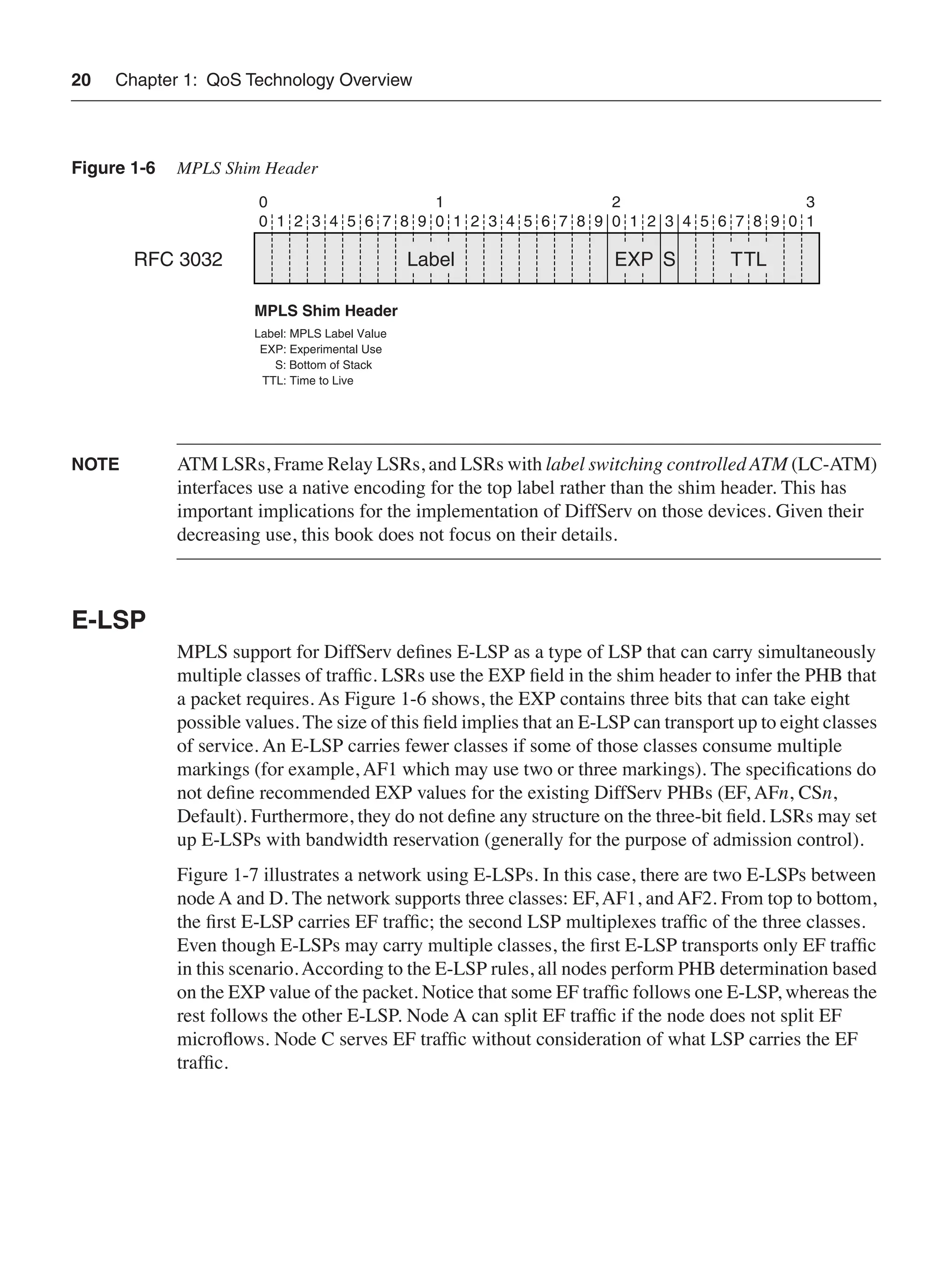
![MPLS Support for DiffServ 21
Figure 1-7 MPLS Network Using an E-LSP
MPLS support for DiffServ defines mechanisms for E-LSPs to signal mappings between
EXP values and PHBs. An LSR associates EXP-to-PHB mappings for input labels and
PHB-to-EXP mappings for output labels. Signaling is optional and takes place during LSP
setup. RFC 3270 defines extensions to LDP (DiffServ TLV [Type, Length, Value] for Label
Request, Label Mapping, Label Release, and Notification messages) and RSVP (DiffServ
object for Path messages) and their appropriate processing. The signaling identifies the LSP
as an E-LSP and specifies the mappings between EXP values and PHBs that it will use.
LSRs can use static but configurable mappings to avoid these signaling extensions for
E-LSPs. An LSR should map all EXP values to the Default PHB if the LSP signaling did
not specify a mapping and no preconfigured mapping exists.
NOTE ATM LSRs, Frame Relay LSRs, and LSRs with LC-ATM interfaces do not forward packets
using an MPLS shim header encapsulation. The absence of a shim header implies the
absence of the EXP field. Therefore, those devices cannot support E-LSPs. This restriction
also applies to nonpacket networks that use generalized MPLS (GMPLS).
IP/MPLS
C
B
D
A
EF Packet AF1 Packet AF2 Packet](https://image.slidesharecdn.com/11004502-250519054220-aad40b60/75/Qos-For-Ipmpls-Networks-Gallo-Mark-Zhang-Raymond-Alvarez-Santiago-41-2048.jpg)