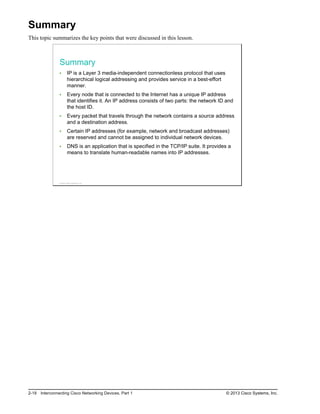
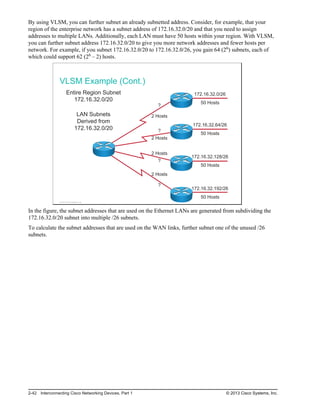
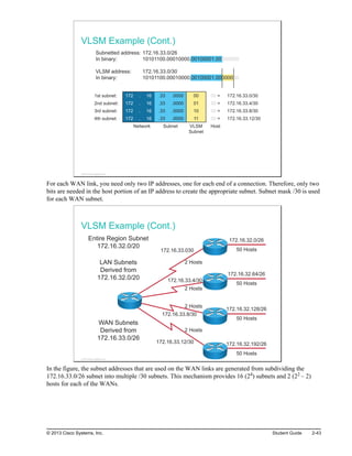
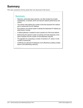
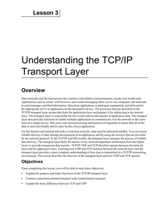
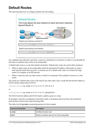
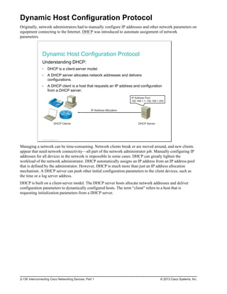
Here are the key points from the overview:
- Understanding the benefits of computer networks and how they function is important in maximizing communication channels among end users.
- This lesson provides a high-level introduction to networking concepts including what a network is, its basic physical components, how networks are represented in diagrams, and how user applications impact networks.
- Characteristics of networks such as bandwidth, latency, reliability and security are described. Physical and logical network topologies are also introduced.
- The lesson provides a foundation for understanding more advanced networking topics covered later in the course.


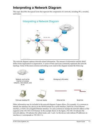
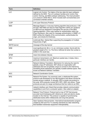
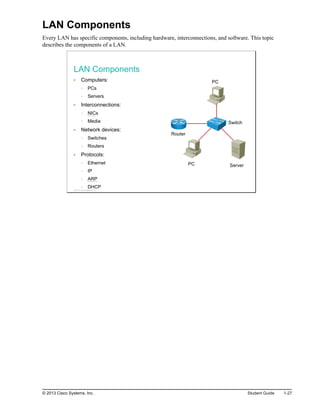
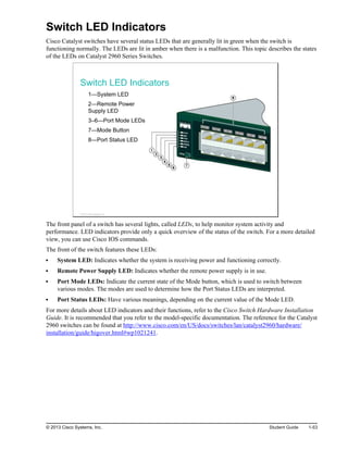
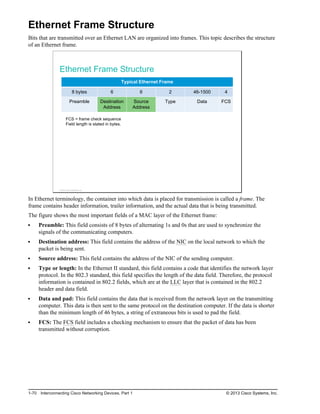
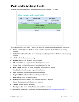
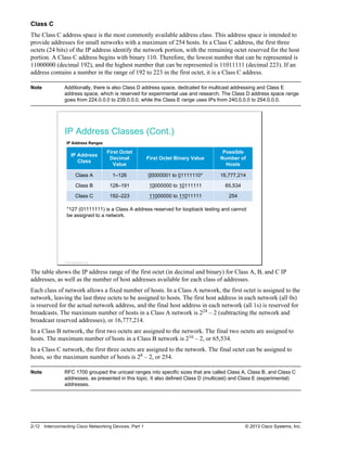
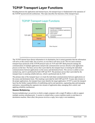
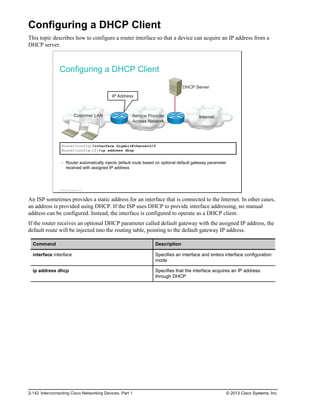
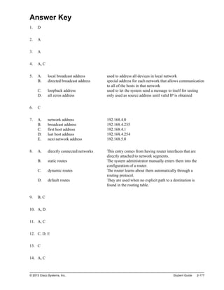
![Characteristics of a Network
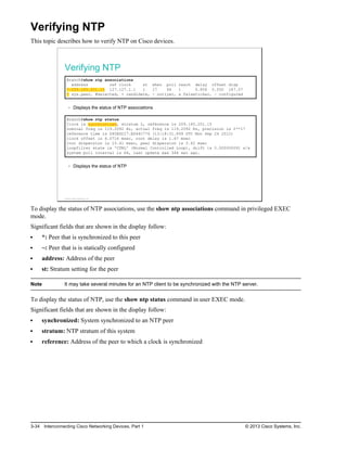
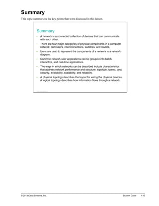
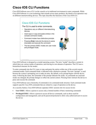
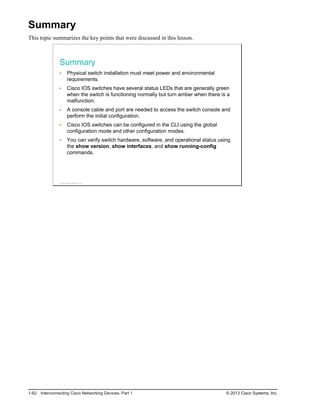
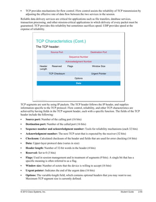
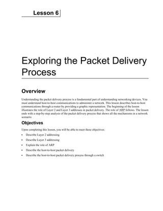
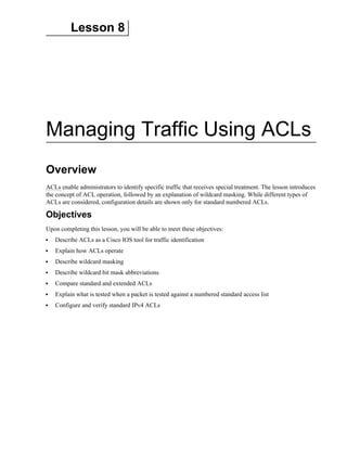
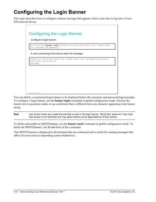
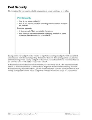
This topic describes the characteristics of a network.
Characteristics of a Network
Topology
Speed
Cost
Security
Availability
Scalability
Reliability
© 2013 Cisco Systems, Inc.
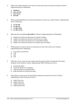
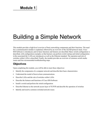
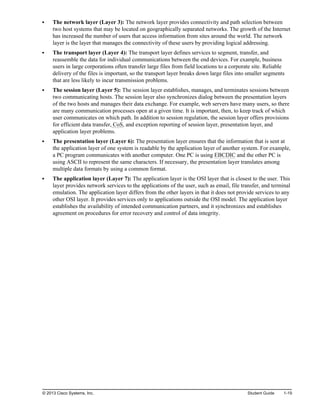
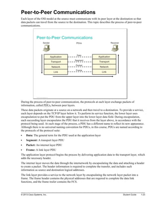
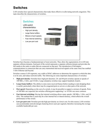
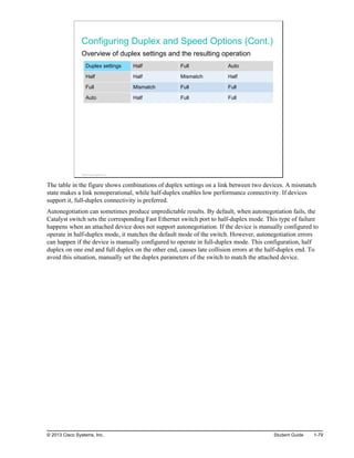
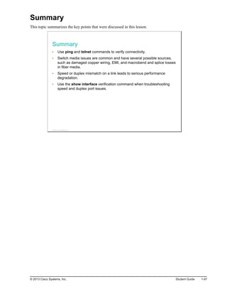
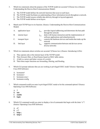
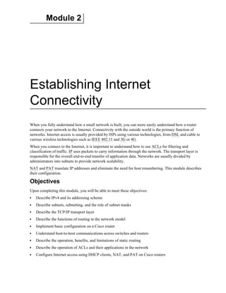
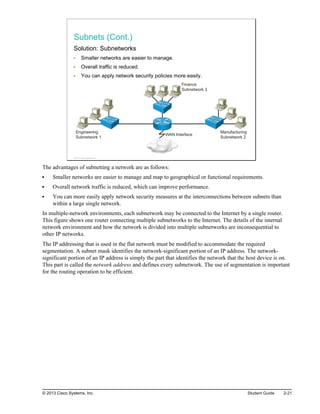
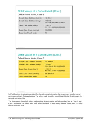
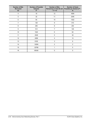
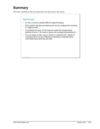
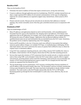
You can describe a network according to performance and structure:
Topology: In networks, there are physical and logical topologies. The physical topology is the
arrangement of the cables, network devices, and end systems. The logical topology is the path over
which the data is transferred in a network. For example, a physical topology describes how the network
devices are actually interconnected with wires and cables. A logical topology describes how the
network devices appear connected to network users.
Speed: Speed is a measure of the data rate in bits per second of a given link in the network.
Cost: Cost indicates the general expense for the purchasing of network components and installation
and maintenance of the network.
Security: Security indicates how protected the network is, including the information that is transmitted
over the network. The subject of security is important, and techniques and practices are constantly
evolving. You should consider security whenever you take actions that affect the network.
Availability: Availability is a measure of the probability that the network will be available for use
when it is required. For networks that are meant to be used 24 hours per day, 7 days per week, 365 days
per year, availability is calculated by dividing the time that it is actually available by the total time in a
year and then multiplying by 100 to get a percentage.
For example, if a network is unavailable for 15 minutes per year because of network outages, you can
calculate its percentage availability as follows:
([Number of minutes in a year – down time] / [number of minutes in a year]) * 100 = percentage
availability
([525600 – 15] / [525600]) * 100 = 99.9971
© 2013 Cisco Systems, Inc. Student Guide 1-9](https://image.slidesharecdn.com/interconnectingcisconetworkingdevices-220917054712-ee97341f/85/Interconnecting_Cisco_Networking_Devices-pdf-27-320.jpg)


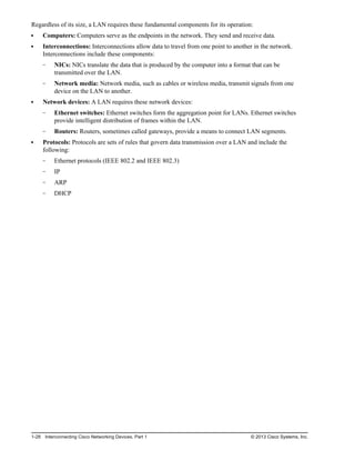

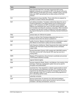
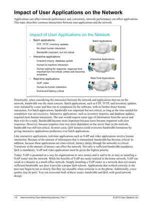
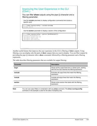
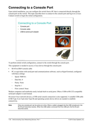
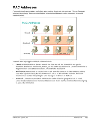
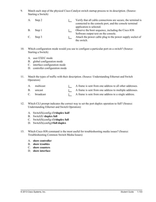
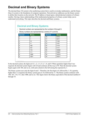
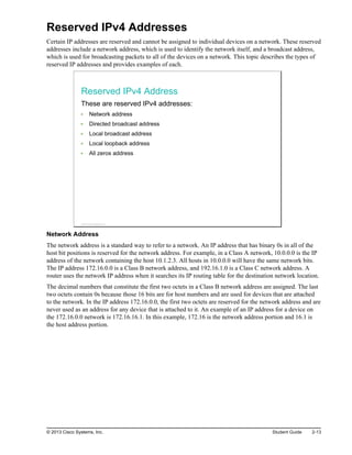
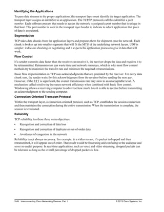
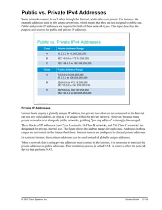
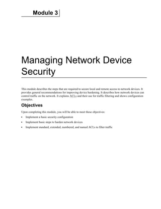
![Managing Cisco IOS Configuration (Cont.)
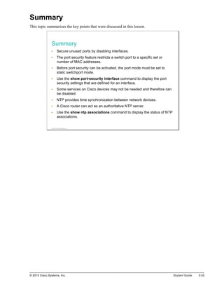
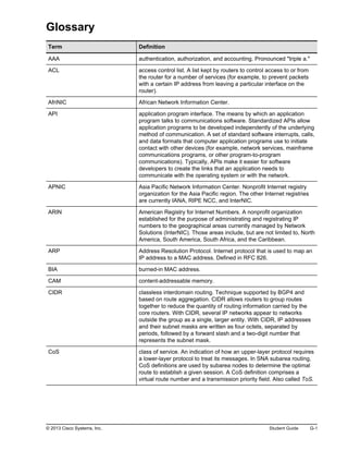
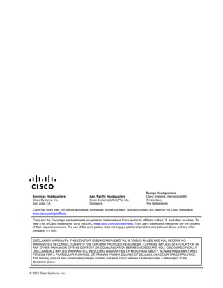
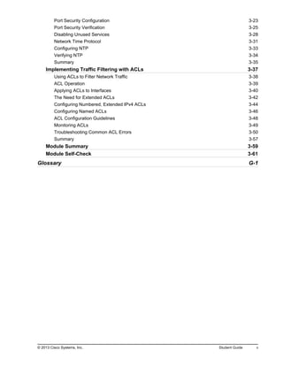
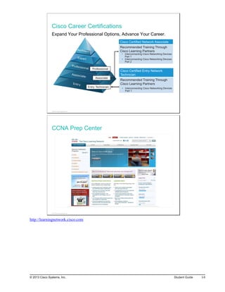
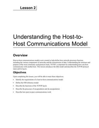
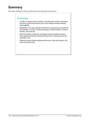
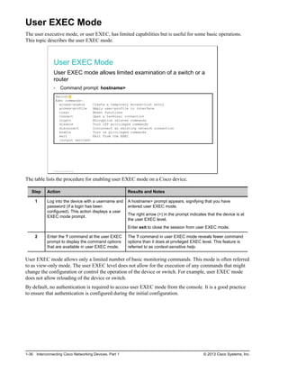
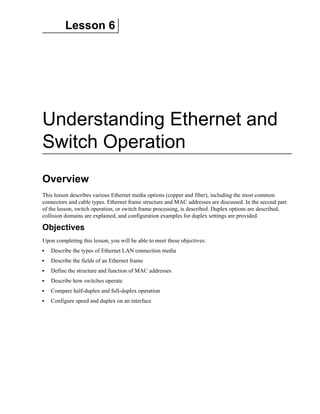
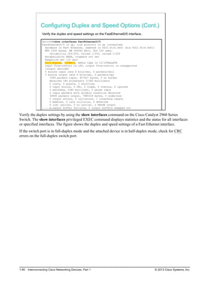
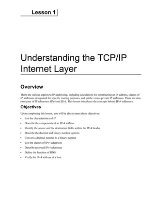
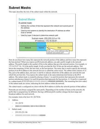
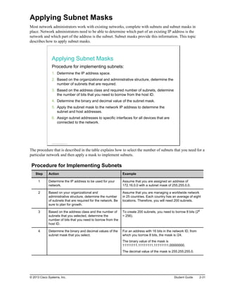
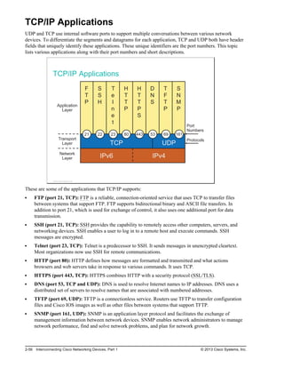
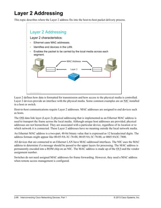
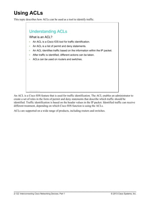
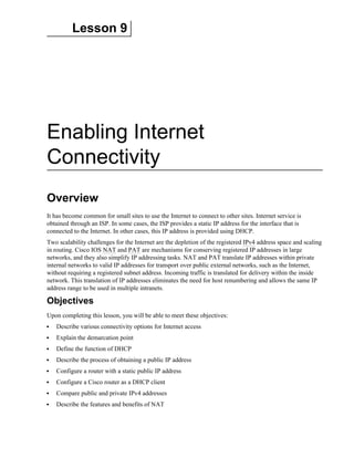
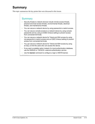
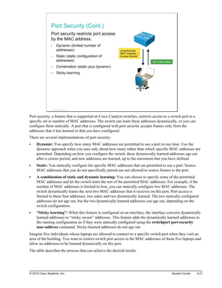
This is how you can save a device configuration:
Switch#copy running-config startup-config
Destination filename [startup-config]?
Building configuration...
[OK]
This is how you back up a configuration to the TFTP server:
Switch#copy running-config tftp:
Address or name of remote host []? 10.1.1.1
Destination filename [running-config]? config.cfg
!!!
1684 bytes copied in 13.300 secs (129 bytes/sec)
© 2013 Cisco Systems, Inc.
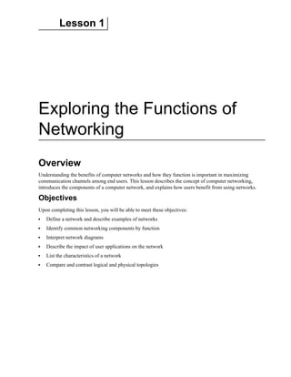
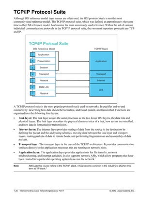
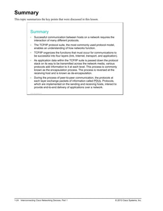
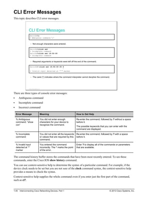
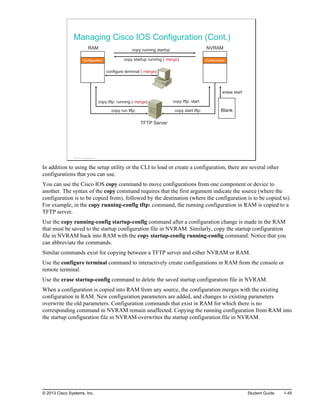
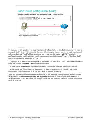
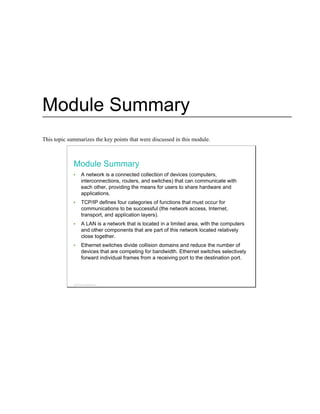
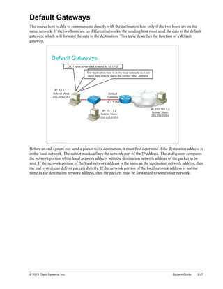
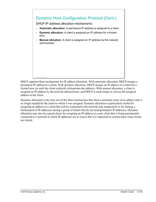
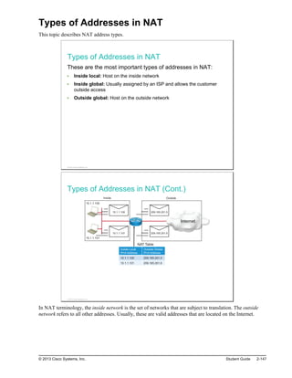
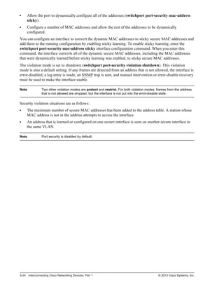
After the commands to configure the router or switch have been entered, you must save the running
configuration to NVRAM with the copy running-config startup-config command. If the configuration is
not saved to NVRAM and the router or switch is reloaded, the configuration will be lost and the router or
switch will revert to the last configuration saved in NVRAM.
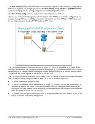
You can use the TFTP servers to store configurations in a central place, allowing centralized management
and updating. Regardless of the size of the network, there should always be a copy of the current running
configuration online as a backup.
The copy running-config tftp: command allows the current configuration to be uploaded and saved to a
TFTP server. The IP address or name of the TFTP server and the destination filename must be supplied.
During the copying process, a series of exclamation marks shows the progress of the upload.
The copy tftp: running-config command downloads a configuration file from the TFTP server to the
running configuration of the RAM. Again, the address or name of the TFTP server and the source and
destination filenames must be supplied. In this case, because you are copying the file to the running
configuration, the destination filename should be running-config. This is a merge process, not an overwrite
process.
1-46 Interconnecting Cisco Networking Devices, Part 1 © 2013 Cisco Systems, Inc.](https://image.slidesharecdn.com/interconnectingcisconetworkingdevices-220917054712-ee97341f/85/Interconnecting_Cisco_Networking_Devices-pdf-64-320.jpg)
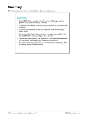

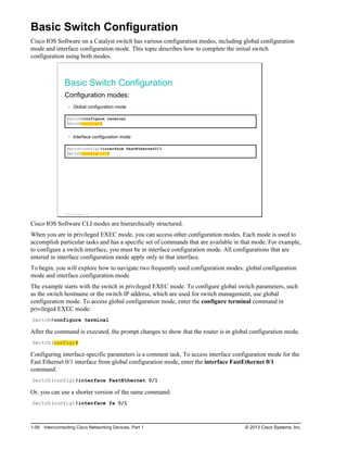
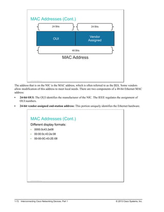


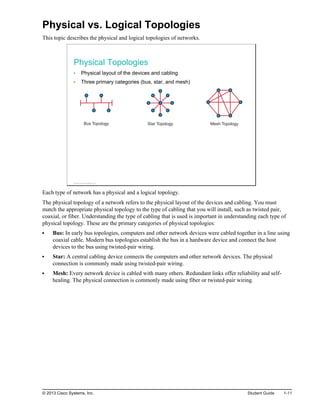
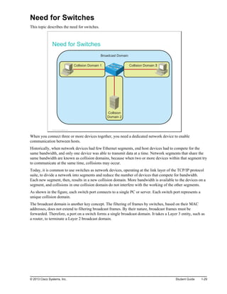
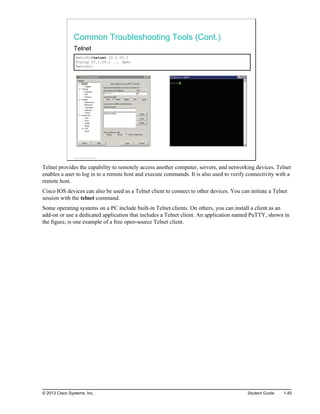
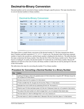
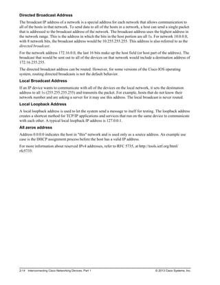
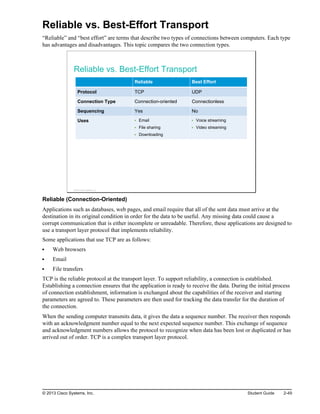
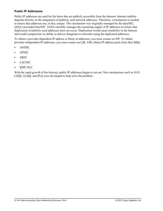
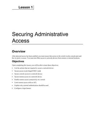
![Common Troubleshooting Tools
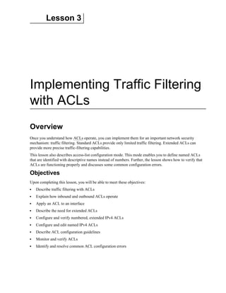
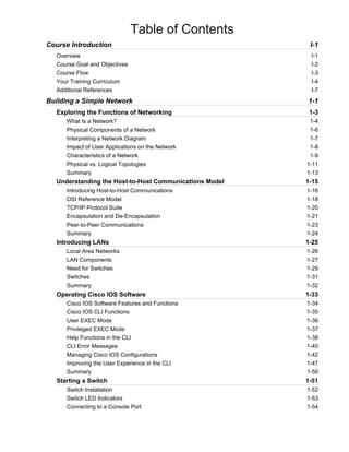
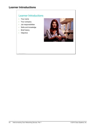
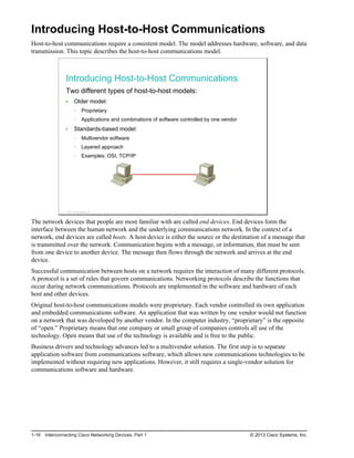
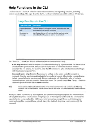
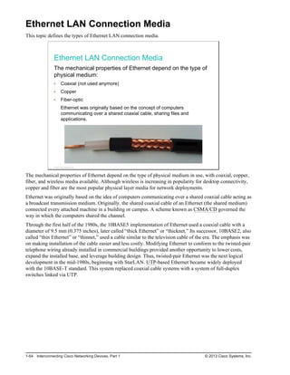
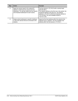
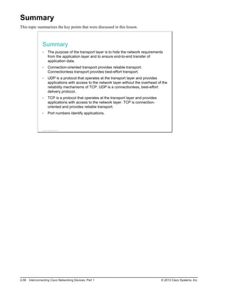
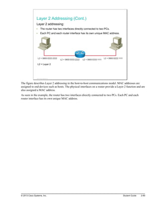
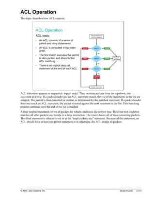
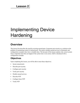
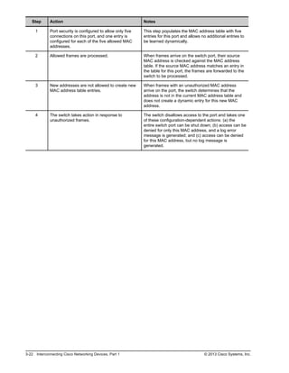
This topic describes common troubleshooting tools that can be used when verifying network connectivity.
Common Troubleshooting Tools
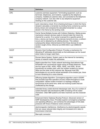
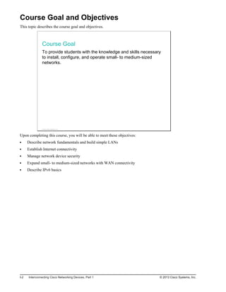
ping command
Switch#ping 10.1.1.100
Type escape sequence to abort.
Sending 5, 100-byte ICMP Echos to 10.1.1.100, timeout is 2 seconds:
!!!!!
Success rate is 100 percent (5/5), round-trip min/avg/max = 1/203/1007 ms
C:>ping example.com
Pinging example.com [192.0.43.10] with 32 bytes of data:
Reply from 192.0.43.10: bytes=32 time=107ms TTL=243
Reply from 192.0.43.10: bytes=32 time=107ms TTL=243
Reply from 192.0.43.10: bytes=32 time=137ms TTL=243
Reply from 192.0.43.10: bytes=32 time=107ms TTL=243
Ping statistics for 192.0.43.10:
Packets: Sent = 4, Received = 4, Lost = 0 (0% loss),
Approximate round trip times in milli-seconds:
Minimum = 107ms, Maximum = 137ms, Average = 114ms
© 2013 Cisco Systems, Inc.
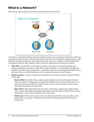
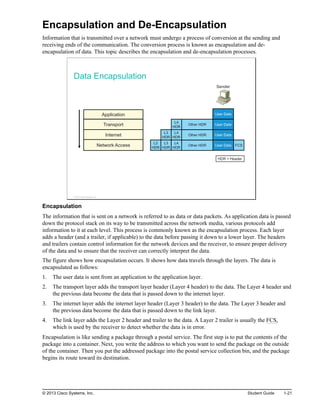
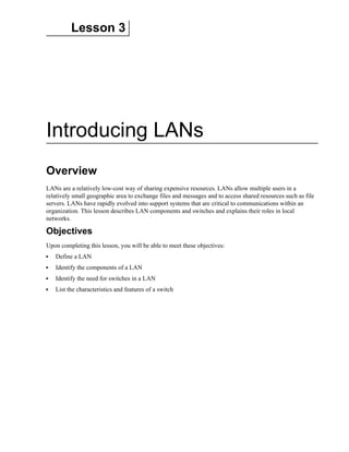
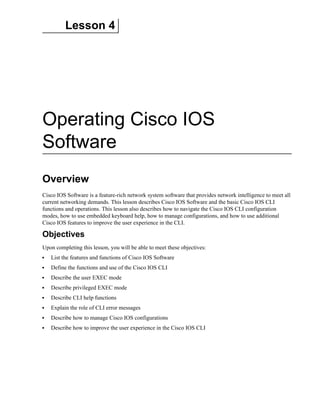
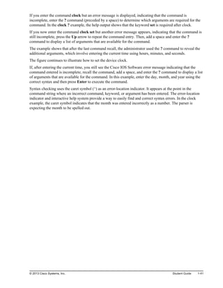
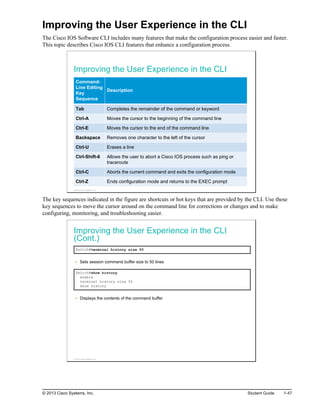
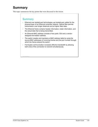
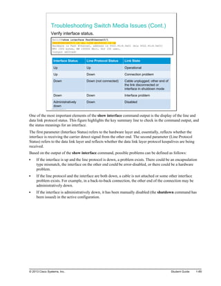
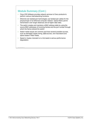
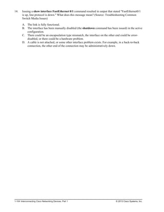
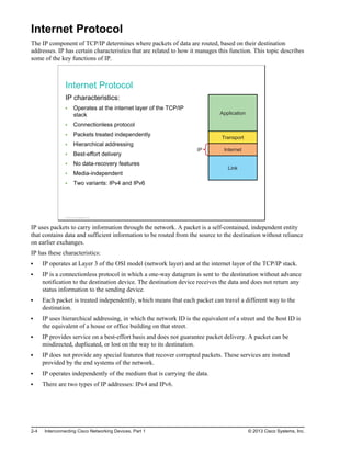
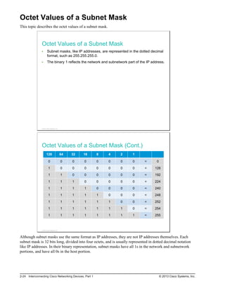
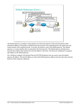
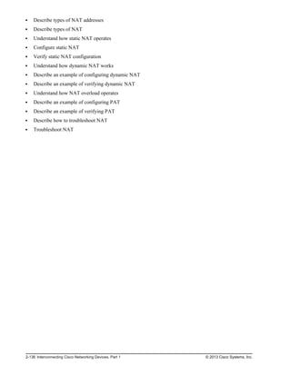
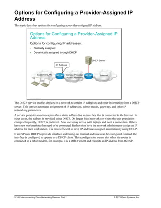
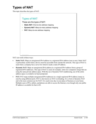
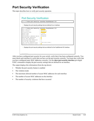
The ping command is a utility for testing IP connectivity between hosts. It sends out requests for responses
from a specified host address. The ping command uses a Layer 3 protocol that is a part of the TCP/IP suite
called ICMP, and it uses the ICMP echo request and ICMP echo reply packets.
If the host at the specified address receives the ICMP echo request, it responds with an ICMP echo reply
packet. For each packet sent, the ping command measures the time that is required to receive the response.
As each response is received, the ping command displays the time between the request being sent and when
the response is received. By using interval timing and response rates, the ping command estimates the RTT,
generally in milliseconds, and the packet-loss rate between hosts. The RTT is a measure of the network
performance.
The ping command is supported on most devices connected to the network, including network devices such
as switches and routers, and different operating systems running on a PC such as Windows, Mac, or Linux.
In the figure, the first output illustrates the use of the ping command on the Cisco Catalyst switch, while the
second output shows ping verification on a PC running Windows.
1-84 Interconnecting Cisco Networking Devices, Part 1 © 2013 Cisco Systems, Inc.](https://image.slidesharecdn.com/interconnectingcisconetworkingdevices-220917054712-ee97341f/85/Interconnecting_Cisco_Networking_Devices-pdf-102-320.jpg)
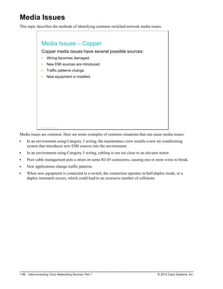


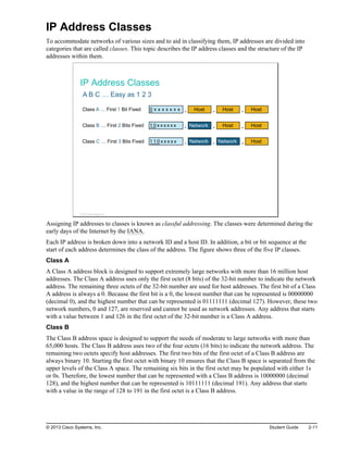
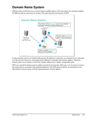
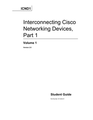
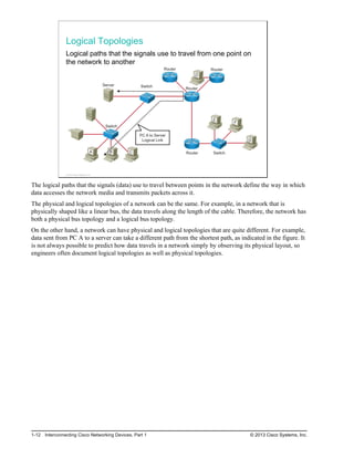
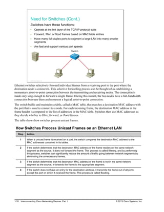
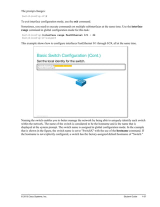
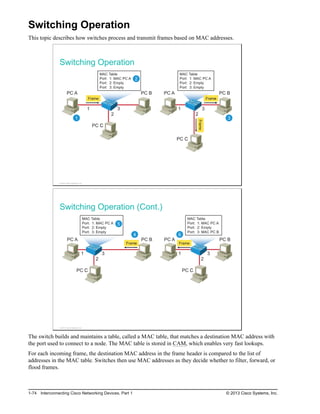
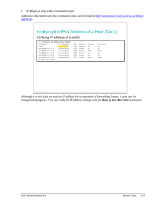
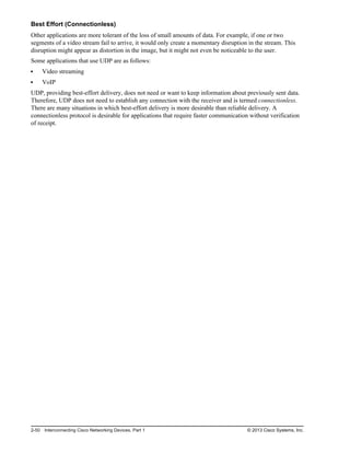
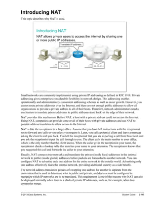
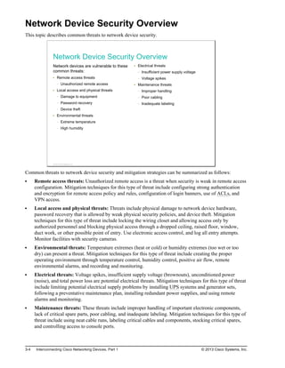
![Verifying the IPv4 Address of a Host
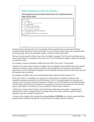
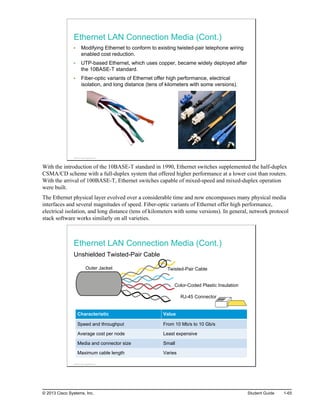
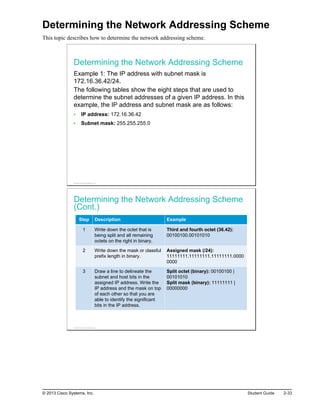
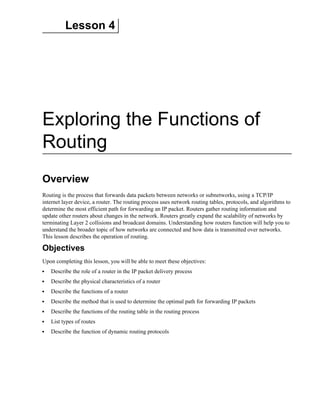
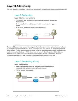
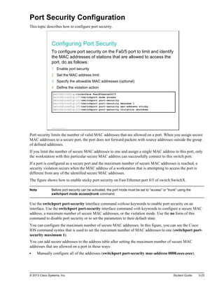
Most operating systems and devices connected to a network provide a set of tools that can be used to verify
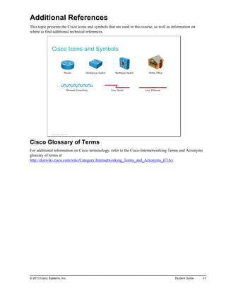
host addressing. This topic focuses on the tools available on the Microsoft Windows platform. Additionally,
it also describes how to verify the IP address of a switch acting as a host.
Verifying the IPv4 Address of a Host
Windows Platform
© 2013 Cisco Systems, Inc.
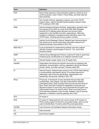
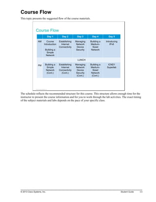
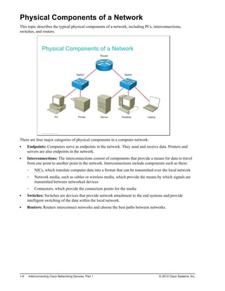
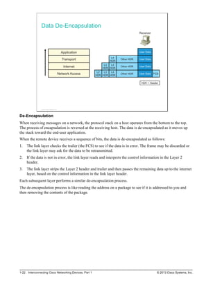
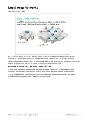
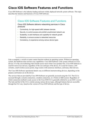
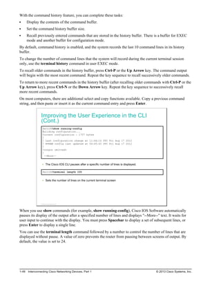
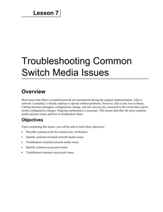
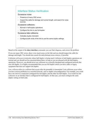
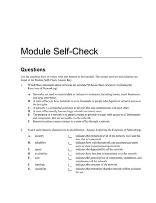
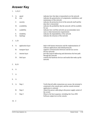
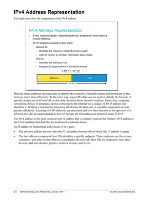
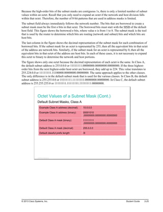
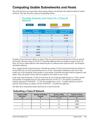
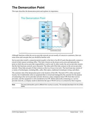
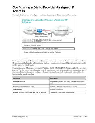
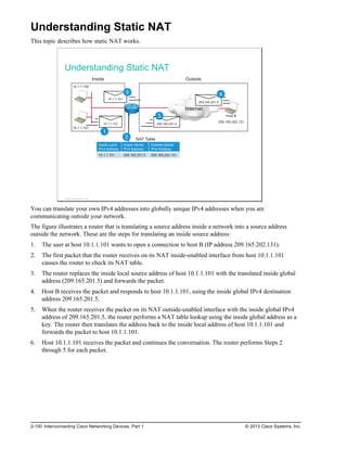
The following describes the syntax for the ipconfig command:
On a PC with the Microsoft Windows operating system, the ipconfig command can be used to display all
current TCP/IP network configuration values at the command line. Using various parameters, the command
can also be used to refresh DHCP and DNS settings. Used without parameters, the ipconfig command
displays the IP address, subnet mask, and default gateway for all adapters.
ipconfig [/all] [/renew [Adapter]] [/release [Adapter]] [/flushdns]
These parameters are commonly used:
/all: Displays the complete TCP/IP configuration for all adapters. Without this parameter, the ipconfig
command displays only the IP address, subnet mask, and default gateway values for each adapter.
Adapters can represent physical interfaces, such as installed network adapters, or logical interfaces,
such as dial-up connections.
/renew [Adapter]: Renews the DHCP configuration for all of the adapters (if an adapter is not
specified) or for a specific adapter if the Adapter parameter is included. This parameter is available
only on computers with adapters that are configured to obtain an IP address automatically. To specify
an adapter name, type the adapter name that appears when you use the ipconfig command without
parameters.
/release [Adapter]: Sends a DHCPRELEASE message to the DHCP server to release the current
DHCP configuration and discard the IP address configuration for either all of the adapters (if an adapter
is not specified) or for a specific adapter if the Adapter parameter is included. This parameter disables
TCP/IP for adapters that are configured to obtain an IP address automatically. To specify an adapter
name, type the adapter name that appears when you use the ipconfig command without parameters.
2-16 Interconnecting Cisco Networking Devices, Part 1 © 2013 Cisco Systems, Inc.](https://image.slidesharecdn.com/interconnectingcisconetworkingdevices-220917054712-ee97341f/85/Interconnecting_Cisco_Networking_Devices-pdf-140-320.jpg)


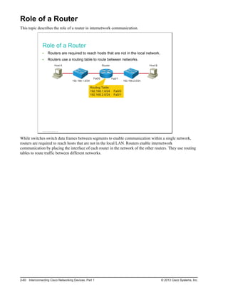
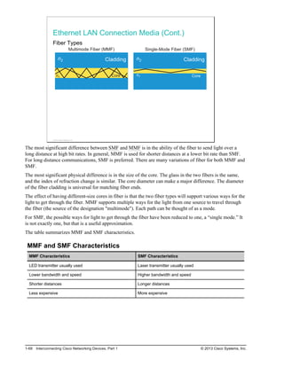
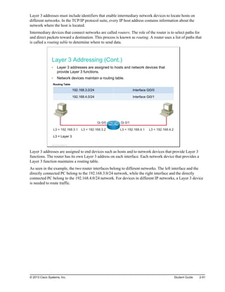
![Management port (console, Ethernet, auxiliary [AUX]): The router uses a console port to attach
to a terminal that is used for management, configuration, and control. High-end routers have a
dedicated Ethernet port used only for management. An IP address is assigned to the Ethernet port
and the router may be accessed from the management subnet. The AUX interface is used for
remote management of the router. Typically, a modem is connected to the AUX interface for dial-
in access. From a security standpoint, enabling the option to connect remotely to a network device
carries with it the responsibility of vigilant device management.
Network port: The router has a number of network ports, including various LAN or WAN media
ports, which may be copper or fiber cable.
2-62 Interconnecting Cisco Networking Devices, Part 1 © 2013 Cisco Systems, Inc.](https://image.slidesharecdn.com/interconnectingcisconetworkingdevices-220917054712-ee97341f/85/Interconnecting_Cisco_Networking_Devices-pdf-186-320.jpg)
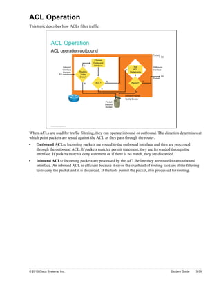
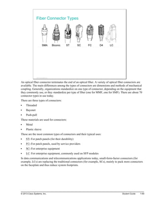
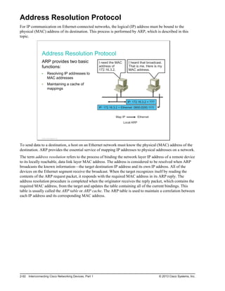
![Router Functions
This topic describes the two most important functions of routers, path determination and packet forwarding.
Router Functions
Path determination
Packet forwarding
RouterA#show ip route
Codes: L - local, C - connected, S - static, R - RIP, M - mobile, B - BGP
D - EIGRP, EX - EIGRP external, O - OSPF, IA - OSPF inter area
N1 - OSPF NSSA external type 1, N2 - OSPF NSSA external type 2
E1 - OSPF external type 1, E2 - OSPF external type 2
<output omitted>
Gateway of last resort is not set
172.17.0.0/16 is variably subnetted, 8 subnets
O 172.17.14.0/24 [110/51] via 172.17.100.22, 1d05h
B 172.17.25.0/24 [200/0] via 172.17.100.22, 6d05h
D 172.17.43.0/24 [90/30720] via 172.17.50.4, 3d20h, GigabitEthernet0/0
C 172.17.50.0/24 is directly connected, GigabitEthernet0/0
L 172.17.50.2/32 is directly connected, GigabitEthernet0/0
S 172.17.92.0/24 [1/0] via 172.17.50.4
C 172.17.100.0/24 is directly connected, GigabitEthernet0/1
L 172.17.100.12/32 is directly connected, GigabitEthernet0/1
Routing table on RouterA
© 2013 Cisco Systems, Inc.
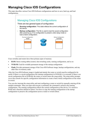
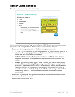
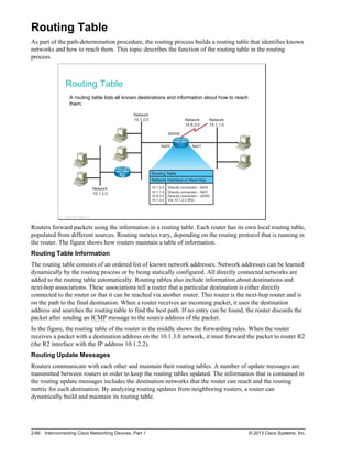
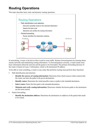
Routers are devices that gather routing information from neighboring routers in the network. The routing
information that is processed locally goes into the routing table. The routing table contains a list of all
known destinations to the router and provides information about how to reach them. Routers have these two
important functions:
Path determination: Routers must maintain their own routing tables and ensure that other routers
know about changes in the network. Routers use a routing protocol to communicate network
information to other routers. A routing protocol distributes the information from a local routing table on
the router. Different protocols use different methods to populate the routing table. In the show ip route
output in the figure, the first letter in each line of the routing table indicates which protocol was the
source for the information (for example, O = OSPF). It is possible to statically populate routing tables
by manually configuring static routes. However, statically populating routing tables does not scale well
and leads to problems when the network topology changes. Design changes and outages can also pose
problems.
Packet forwarding: Routers use the routing table to determine where to forward packets. Routers
forward packets through a network interface toward the destination network. Each line of the routing
table indicates which network interface is used to forward a packet. The destination IP address in the
packet defines the packet destination. Routers use their local routing table and compare the entries to
the destination IP address of the packet. The result is a decision about which outgoing interface to use
to send the packet out of the router. If routers do not have a matching entry in their routing tables, the
packets are dropped.
Routers support three packet-forwarding mechanisms:
Process switching: Process switching is the oldest forwarding mechanism that is available in
Cisco routers. Every packet requires full lookup in the routing table, which makes this mechanism
very slow. It is typically not used in modern networks.
© 2013 Cisco Systems, Inc. Student Guide 2-63](https://image.slidesharecdn.com/interconnectingcisconetworkingdevices-220917054712-ee97341f/85/Interconnecting_Cisco_Networking_Devices-pdf-187-320.jpg)
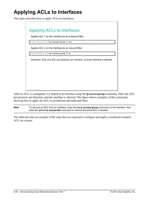
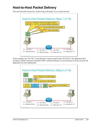
![Types of Routes
Routers can learn about other networks via directly connected networks, static routes, dynamic routes, and
default routes. This topic describes each of these types of routes.
Types of Routes
RouterA#show ip route
Codes: L - local, C - connected, S - static, R - RIP, M - mobile, B - BGP
D - EIGRP, EX - EIGRP external, O - OSPF, IA - OSPF inter area
N1 - OSPF NSSA external type 1, N2 - OSPF NSSA external type 2
E1 - OSPF external type 1, E2 - OSPF external type 2
i - IS-IS, su - IS-IS summary, L1 - IS-IS level-1, L2 - IS-IS level-2
ia - IS-IS inter area, * - candidate default, U - per-user static route
o - ODR, P - periodic downloaded static route, + - replicated route
Gateway of last resort is 10.1.1.1 to network 0.0.0.0
C 10.1.1.0/24 is directly connected, GigabitEthernet0/0
L 10.1.1.2/32 is directly connected, GigabitEthernet0/0
O 172.16.1.0/24 [110/2] via 192.168.10.2, 00:01:08, GigabitEthernet0/1
D 192.168.20.0/24 [90/156160] via 10.1.1.1, 00:01:23, GigabitEthernet0/0
S 192.168.30.0/24 [1/0] via 192.168.10.2
C 192.168.10.0/24 is directly connected, GigabitEthernet0/1
L 192.168.10.1/32 is directly connected, GigabitEthernet0/1
S* 0.0.0.0/0 [1/0] via 10.1.1.1
© 2013 Cisco Systems, Inc.
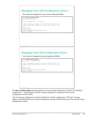
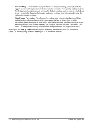
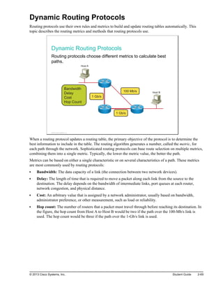
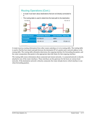
The routing table can be populated by these methods:
Directly connected networks: This entry comes from having router interfaces that are directly
attached to network segments. This method is the most certain method of populating a routing table. If
the interface fails or is administratively shut down, the entry for that network is removed from the
routing table. The administrative distance is 0 and therefore preempts all other entries for that
destination network. Entries with the lowest administrative distance are the best, most-trusted sources.
Static routes: A system administrator manually enters static routes directly into the configuration of a
router. The default administrative distance for a static route is 1; therefore, static routes will be included
in the routing table unless there is a direct connection to that network. Static routes can be an effective
method for small, simple networks that do not change frequently. For bigger or unstable networks,
static routes are not a scalable solution.
Dynamic routes: The router learns dynamic routes automatically when a routing protocol is
configured and a neighbor relationship to other routers is established. The information changes with
changes in the network and updates constantly. Larger networks require the dynamic routing method
because there are usually many addresses and constant changes. These changes require updates to
routing tables across all routers in the network, or connectivity is lost.
Default routes: A default route is an optional entry that is used when no explicit path to a destination
is found in the routing table. The default route can be manually inserted or it can be populated from a
dynamic routing protocol.
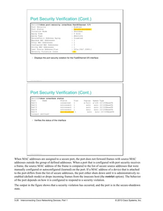
The figure displays the show ip route command, which is used to show the contents of the routing table in
a router. The first part of the output explains the codes, presenting the letters and the associated source of
the entries in the routing table.
The letter C, which is reserved for directly connected networks, labels the first and seventh entries.
© 2013 Cisco Systems, Inc. Student Guide 2-67](https://image.slidesharecdn.com/interconnectingcisconetworkingdevices-220917054712-ee97341f/85/Interconnecting_Cisco_Networking_Devices-pdf-191-320.jpg)


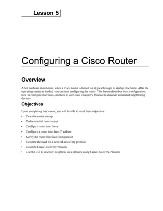
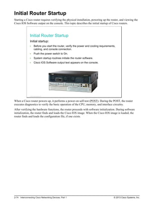
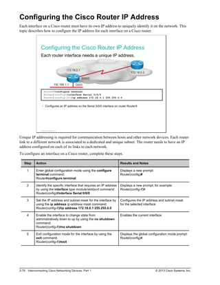
![Initial Router Setup
When the router starts, it looks for a device configuration file. If it does not find one, the router executes a
question-driven initial configuration routine called setup. This topic describes the initial command-line
output and explains how to skip the setup dialog.
Initial Router Setup
Console
RouterX con0 is now available
Press RETURN to get started.
RouterX>
A configured router with an existing configuration displays a user EXEC mode prompt.
--- System Configuration Dialog ---
Would you like to enter the initial configuration dialog? [yes/no]:
A router without an existing configuration enters the system configuration dialog.
© 2013 Cisco Systems, Inc.
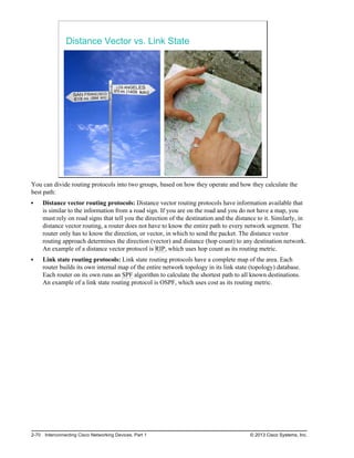
After a router completes the POST and loads a Cisco IOS image, it looks for a device configuration file in
its NVRAM. The NVRAM of the router is a type of memory that retains its contents, even when power is
turned off. If the router has a configuration file in NVRAM, the user EXEC mode prompt appears. The
figure shows the RouterX> prompt.
When you start a new Cisco router or a Cisco router without a configuration in NVRAM, there will be no
configuration file. If no valid configuration file exists in NVRAM, the operating system executes a
question-driven initial configuration routine that is referred to as the system configuration dialog or setup
mode.
The system configuration dialog is an interactive CLI mode that prompts you for information that is needed
to build an initial configuration for a Cisco networking device. It is not intended for more advanced
configuration. Rather than using setup mode, you can use various other manual configuration modes to
configure the router.
To skip the system configuration dialog and configure the router manually, answer the first question in the
system configuration dialog with No or press Ctrl-C. If desired, you can enter the system configuration
dialog anytime by issuing the setup command in privileged EXEC mode.
© 2013 Cisco Systems, Inc. Student Guide 2-75](https://image.slidesharecdn.com/interconnectingcisconetworkingdevices-220917054712-ee97341f/85/Interconnecting_Cisco_Networking_Devices-pdf-199-320.jpg)
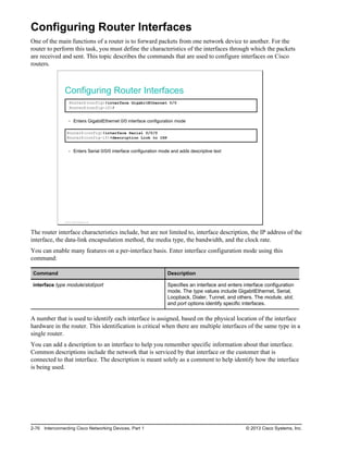
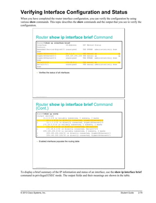
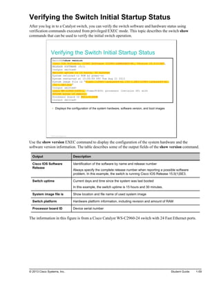
![Using the show cdp neighbors detail
Command
SW1 Branch HQ
Gi0/0
Fa0/13
192.168.1.2
192.168.1.1
10.1.1.1
10.1.1.11
S0/0/0
S0/0/1
Branch#show cdp neighbors detail
-------------------------
Device ID: HQ
Entry address(es):
IP address: 192.168.1.2
Platform: Cisco CISCO2901/K9, Capabilities: Router Switch IGMP
Interface: Serial0/0/0, Port ID (outgoing port): Serial0/0/1
Holdtime: 132 sec
Version: Cisco IOS Software, C2900 Software (C2900-UNIVERSALK9-M),
Version 15.2(4)M1, RELEASE SOFTWARE (fc1)
Technical Support: http://www.cisco.com/techsupport
Copyright (c) 1986-2012 by Cisco Systems, Inc.
Compiled Tue 20-Mar-12 18:57 by prod_rel_team
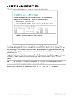
<output omitted>
Displays detailed information about neighboring devices
© 2013 Cisco Systems, Inc.
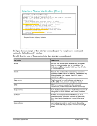
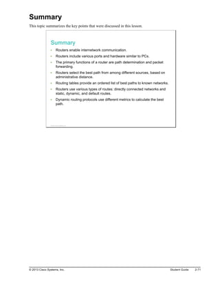
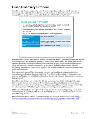
The show cdp neighbors detail or show cdp entry * command displays detailed information about
neighboring devices. To display information about a specific neighbor, the command string must include
the IP address or device ID of the neighbor. The show cdp entry command shows the following
information:
Neighbor device ID (router HQ in the figure)
OSI Layer 3 protocol information (for example, IP address 192.168.1.2 in the figure)
Device platform (Cisco 2901 in the figure)
Device capabilities (router, switch, IGMP in the figure)
Local interface type and outgoing remote port ID (Serial 0/0/0 in the figure)
Hold time value, in seconds (132 seconds in the figure)
Cisco IOS Software type and release (C2900 Software [C2900-UNIVERSALK9-M], Version
15.2[4]M1, in the figure)
For more details about show cdp commands, refer to the Cisco IOS Network Management Command
Reference at http://www.cisco.com/en/US/docs/ios/netmgmt/command/reference/nm_12.html#wp1115418
© 2013 Cisco Systems, Inc. Student Guide 2-85](https://image.slidesharecdn.com/interconnectingcisconetworkingdevices-220917054712-ee97341f/85/Interconnecting_Cisco_Networking_Devices-pdf-209-320.jpg)
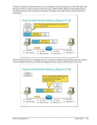
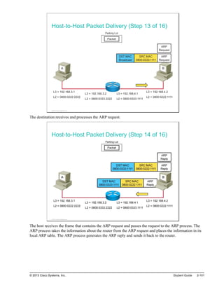
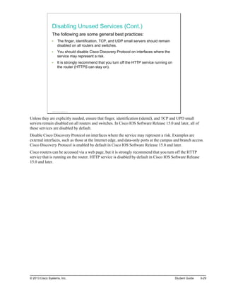
![Address Resolution Protocol (Cont.)
The ARP table keeps a record of recent bindings of IP
addresses to MAC addresses.
On the PC:
C:Windowssystem32>arp -a
Interface: 192.168.250.11 --- 0xb
Internet Address Physical Address Type
192.168.250.1 00-1b-0c-5d-91-0f dynamic
192.168.250.12 00-0c-29-13-cc-bf dynamic
On the router:
Branch#show ip arp
Protocol Address Age (min) Hardware Addr Type Interface
Internet 10.1.1.100 5 000c.2993.6a84 ARPA GigabitEthernet0/0
Internet 10.1.1.101 4 000c.2913.ccc9 ARPA GigabitEthernet0/0
© 2013 Cisco Systems, Inc.
Each IP device on a network segment maintains a table in memory: the ARP table. This table maps the IP
addresses of other devices on the network with their physical (MAC) addresses. When a host wants to
transmit data to another host on the same network, it searches the ARP table to see if there is an entry. If
there is an entry, the host uses it. If there is not, ARP is used to get an entry.
Each entry, or row, of the ARP table has a pair of values: an IP address and a MAC address. The
relationship between the two values is a map, which simply means that you can locate an IP address in the
table and discover the corresponding MAC address. The ARP table caches the mapping for the devices on
the local LAN.
The ARP table is created and maintained dynamically. It adds and changes address relationships as they are
used on the local host. The entries in an ARP table on a PC usually expire after 300 seconds, which is the
default value. It takes up to four hours by default on routers. Such timeout ensures that the table does not
contain information for systems that may be switched off or that have been moved. When the local host
wants to transmit data again, the entry in the ARP table is regenerated through the ARP process.
If no device responds to the ARP request, the packet is dropped because a frame cannot be created.
The arp -a command displays the current ARP table for all interfaces on a PC using the Microsoft
Windows operating system.
To display the ARP table on the router, use the show ip arp EXEC command as follows:
show ip arp [ip-address] [host-name] [mac-address] [interface type number]
Syntax Description
Parameter Description
ip-address (Optional) Displays ARP entries matching this IP address
host-name (Optional) Hostname
© 2013 Cisco Systems, Inc. Student Guide 2-93](https://image.slidesharecdn.com/interconnectingcisconetworkingdevices-220917054712-ee97341f/85/Interconnecting_Cisco_Networking_Devices-pdf-217-320.jpg)

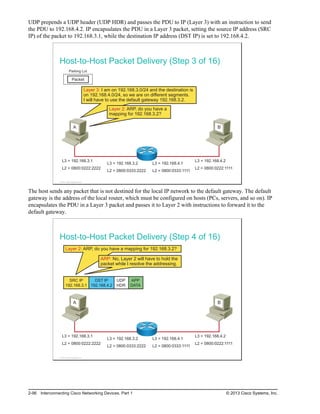
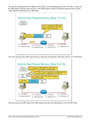
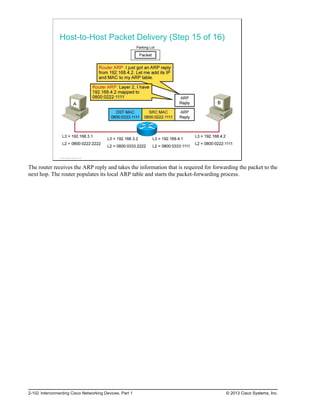


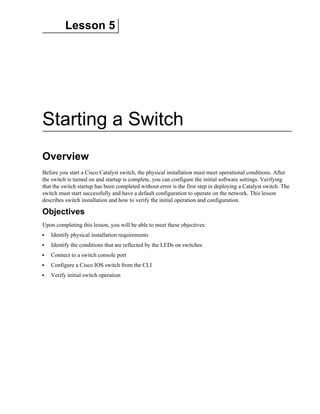
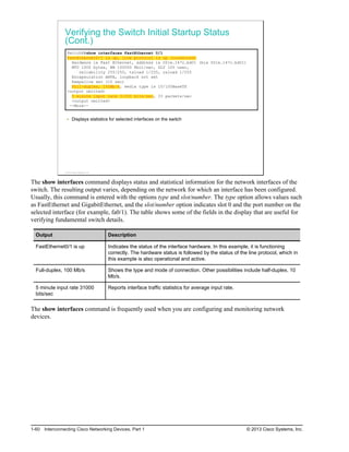
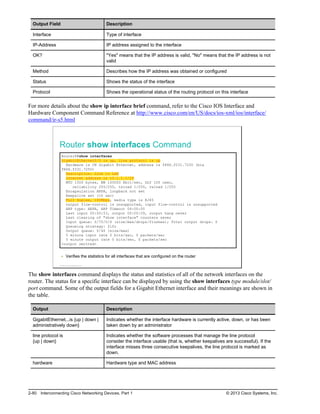
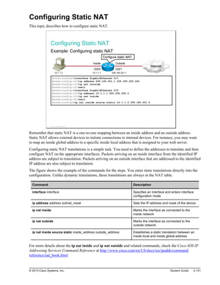
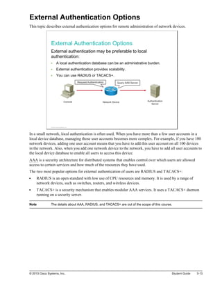
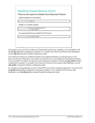
![Static Route Configuration Verification
This topic describes how to verify static route configuration.
Static Route Configuration Verification
RouterA#show ip route
Codes: L - local, C - connected, S - static, R - RIP, M - mobile, B - BGP
D - EIGRP, EX - EIGRP external, O - OSPF, IA - OSPF inter area
N1 - OSPF NSSA external type 1, N2 - OSPF NSSA external type 2
<output omitted>
Gateway of last resort is not set
10.0.0.0/24 is subnetted, 1 subnets
C 10.0.0.0 is directly connected, FastEthernet0/0
172.16.0.0/24 is subnetted, 2 subnets
S 172.16.1.0/24 [1/0] via 172.16.2.1
C 172.16.2.0/24 is directly connected, Serial0/0/0
L 172.16.2.2/32 is directly connected, Serial0/0/0
© 2013 Cisco Systems, Inc.
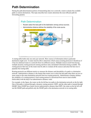
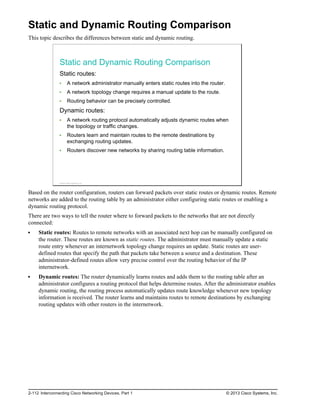
Static Route Configuration Verification (Cont.)
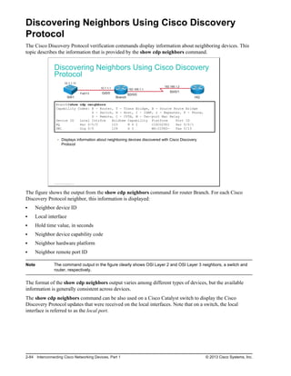
To verify static routes in the routing table, examine the routing
table with the show ip route command:
Includes network address and subnet mask as well as IP address of
next-hop router or exit interface
Denoted with the code “S” in the routing table
Routing tables must contain directly connected networks that
are used to connect remote networks before static or dynamic
routing can be used.
© 2013 Cisco Systems, Inc.
Most routing tables contain a combination of static routes and dynamic routes. However, the routing table
must first contain the directly connected networks that are used to access the remote networks before any
static or dynamic routing can be used.
2-118 Interconnecting Cisco Networking Devices, Part 1 © 2013 Cisco Systems, Inc.](https://image.slidesharecdn.com/interconnectingcisconetworkingdevices-220917054712-ee97341f/85/Interconnecting_Cisco_Networking_Devices-pdf-242-320.jpg)
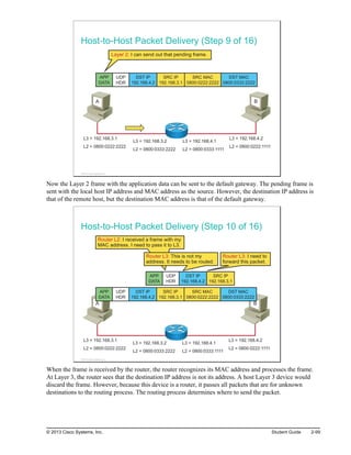
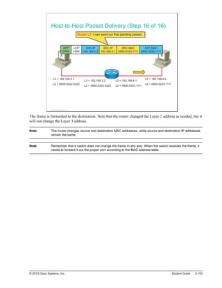
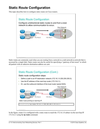
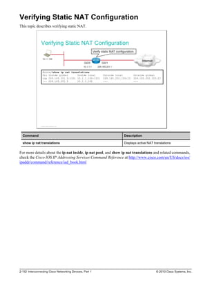
![A static route includes the network address and subnet mask of the remote network, along with the IP
address of the next-hop router or exit interface. Static routes are denoted with the code “S” in the routing
table, as shown in the figure.
When you configure a static route to use an exit interface instead of a next-hop IP address, the routing table
entry is changed as follows:
RouterA#show ip route
Codes: L - local, C - connected, S - static, R - RIP, M - mobile, B - BGP
D - EIGRP, EX - EIGRP external, O - OSPF, IA - OSPF inter area
N1 - OSPF NSSA external type 1, N2 - OSPF NSSA external type 2
<output omitted>
Gateway of last resort is not set
10.0.0.0/24 is subnetted, 1 subnets
C 10.0.0.0 is directly connected, FastEthernet0/0
172.16.0.0/24 is subnetted, 2 subnets
S 172.16.1.0/24 is directly connected, Serial0/0/0
C 172.16.2.0/24 is directly connected, Serial0/0/0
L 172.16.2.2/32 is directly connected, Serial0/0/0
Note that the entry in the routing table no longer refers to the next-hop IP address but refers directly to the
exit interface. This exit interface is the same one to which the static route was resolved when it used the
next-hop IP address. Now that the routing table process has a match for a packet and this static route, it is
able to resolve the route to an exit interface in a single lookup.
Note The static route displays the route as directly connected. It is important to understand that this does not
mean that this route is a directly connected network or a directly connected route. This route is still a
static route.
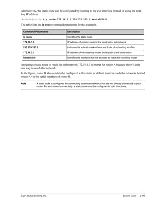
Verifying the Default Route Configuration
To verify the default route configuration, examine the routing
table on RouterB:
RouterB#show ip route
Codes: L - local, C - connected, S - static,
R - RIP, M - mobile, B - BGP
<output omitted>
Gateway of last resort is 172.16.2.2 to network 0.0.0.0
172.16.0.0/24 is subnetted, 2 subnets
C 172.16.1.0/24 is directly connected, FastEthernet0/0
C 172.16.2.0/24 is directly connected, Serial0/0/0
S* 0.0.0.0/0 [1/0] via 172.16.2.2
© 2013 Cisco Systems, Inc.
The example in the figure shows the RouterB routing table after configuration of the default route.
The asterisk (*) indicates the last path option that the router will use when forwarding a packet.
© 2013 Cisco Systems, Inc. Student Guide 2-119](https://image.slidesharecdn.com/interconnectingcisconetworkingdevices-220917054712-ee97341f/85/Interconnecting_Cisco_Networking_Devices-pdf-243-320.jpg)


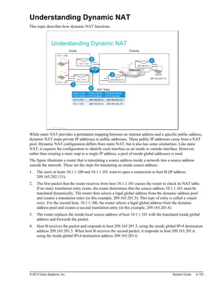


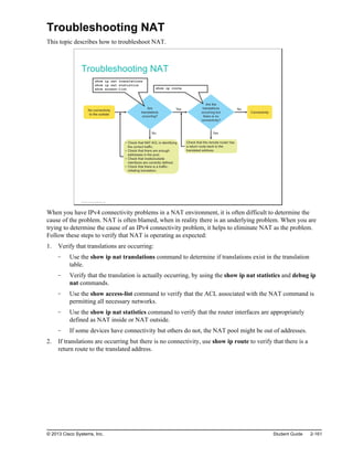
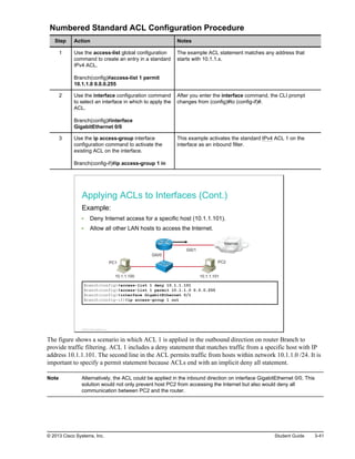
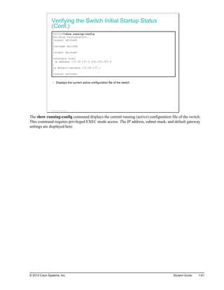
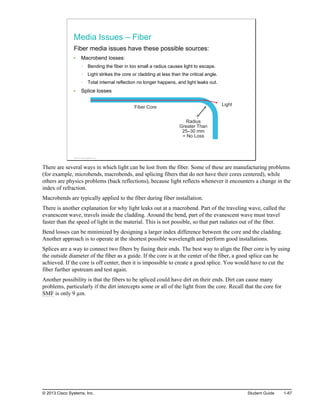
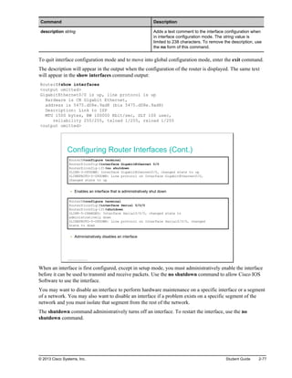
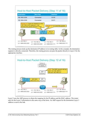
![Troubleshooting NAT (Cont.)
To display detailed dynamic data and events, you can use debug
commands.
A debug command can intensively use device resources. Use carefully on
production equipment.
Always turn off debug after troubleshooting with the no debug all command.
Router#debug ip nat
NAT*: s=10.1.1.100->209.165.201.1, d=172.16.1.100 [103]
NAT*: s=172.16.1.100, d=209.165.201.1->10.1.1.100 [103]
NAT*: s=10.1.1.100->209.165.201.1, d=172.16.1.100 [104]
NAT*: s=172.16.1.100, d=209.165.201.1->10.1.1.100 [104]
<output omitted>
Displays information about every packet that is translated by the router
© 2013 Cisco Systems, Inc.
Note The debug command, especially the debug all command, should be used sparingly. These commands
can disrupt router operations. The debug commands are useful when configuring or troubleshooting a
network. However, they can make intensive use of CPU and memory resources. It is recommended that
you run as few debug processes as necessary and disable them immediately when they are no longer
needed. The debug commands should be used with caution on production networks because they can
affect the performance of the device.
The debug ip nat command displays information about every packet that the router translates, which helps
you to verify NAT operation. The debug ip nat detailed command generates a description of each packet
that is considered for translation. This command also provides information about certain errors or exception
conditions, such as the failure to allocate a global address. The debug ip nat detailed command generates
more overhead than the debug ip nat command, but it can provide the detail that you need to troubleshoot
the NAT problem. Always remember to turn off debugging when finished.
The figure shows a sample debug ip nat output. In the output, you can see that inside host 10.1.1.100
initiated traffic to outside host 209.165.202.131 and has been translated to address 209.165.201.5.
For decoding the debug output, note what the following symbols and values indicate:
*: The asterisk next to "NAT" indicates that the translation is occurring in the fast-switched path. The
first packet in a conversation is always process-switched, which is slower. The remaining packets go
through the fast-switched path if a cache entry exists.
s=: Refers to the source IP address.
a.b.c.d->w.x.y.z: Indicates that source address a.b.c.d is translated to w.x.y.z.
d=: Refers to the destination IP address.
[xxxx]: The value in brackets is the IP identification number. This information may be useful for
debugging because it enables correlation with other packet traces from protocol analyzers.
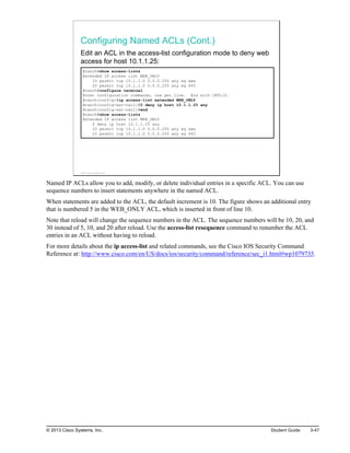
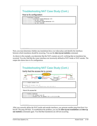
Finally, you should make sure that the ACL that the NAT command references is permitting all of the
necessary networks. Notice that ACLs use wildcard masks and not subnet masks.
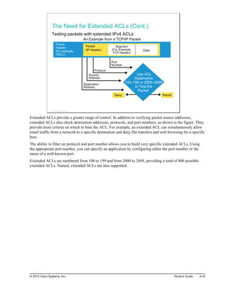
© 2013 Cisco Systems, Inc. Student Guide 2-163](https://image.slidesharecdn.com/interconnectingcisconetworkingdevices-220917054712-ee97341f/85/Interconnecting_Cisco_Networking_Devices-pdf-287-320.jpg)
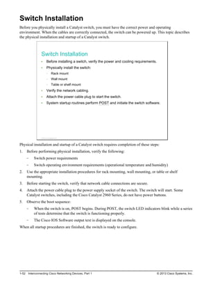
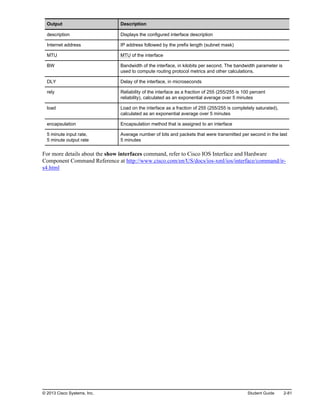
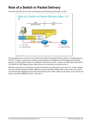
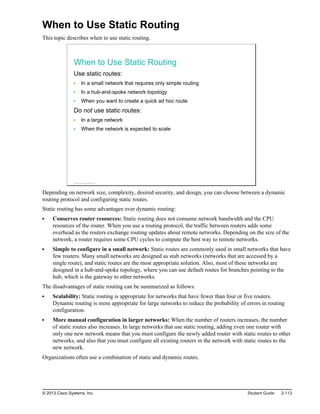
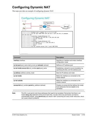
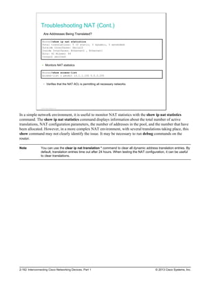
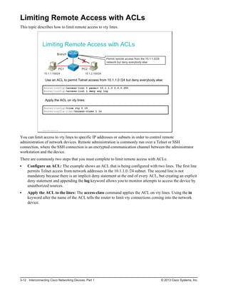
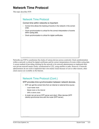
![Troubleshooting NAT (Cont.)
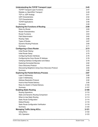
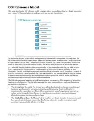
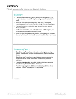
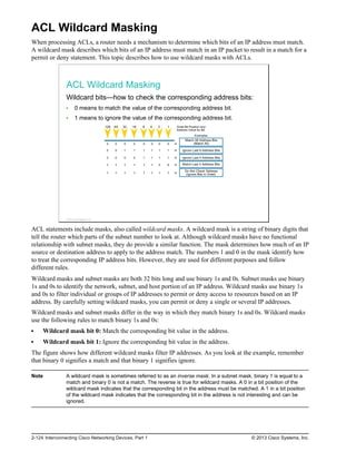
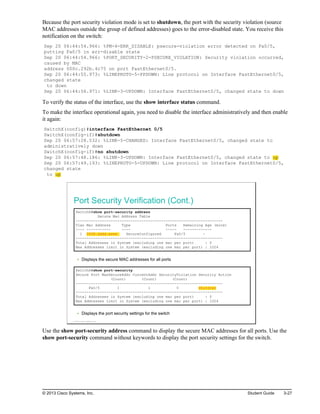
If translations are occurring, but there is no connectivity, verify
that the remote router has a route to the translated address.
10.1.1.100
10.1.1.1
209.165.201.1
209.165.201.2
10.1.1.100
HQ Branch
NAT
Branch#show ip route
Codes: L - local, C - connected, S - static, R - RIP, M - mobile, B - BGP
D - EIGRP, EX - EIGRP external, O - OSPF, IA - OSPF inter area
N1 - OSPF NSSA external type 1, N2 - OSPF NSSA external type 2
E1 - OSPF external type 1, E2 - OSPF external type 2
i - IS-IS, su - IS-IS summary, L1 - IS-IS level-1, L2 - IS-IS level-2
ia - IS-IS inter area, * - candidate default, U - per-user static route
o - ODR, P - periodic downloaded static route, + - replicated route
Gateway of last resort is 209.165.201.1 to network 0.0.0.0
C 10.1.1.0/24 is directly connected, GigabitEthernet0/0
L 10.1.1.2/32 is directly connected, GigabitEthernet0/0
C 209.165.201.0/27 is directly connected, GigabitEthernet0/1
S* 0.0.0.0/0 [1/0] via 209.165.201.1
© 2013 Cisco Systems, Inc.
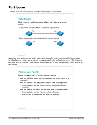
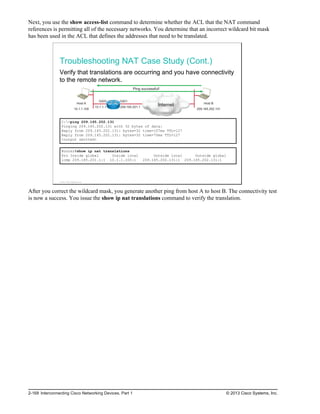
If the translations are occurring but a ping to the remote network still fails, the issue might be a missing
route back to the translated address. This problem can arise in NAT between a headquarters and branch
office. It is usually not an issue when connecting to an ISP, because the service provider takes care of
routing all of the necessary traffic back to the customer.
2-164 Interconnecting Cisco Networking Devices, Part 1 © 2013 Cisco Systems, Inc.](https://image.slidesharecdn.com/interconnectingcisconetworkingdevices-220917054712-ee97341f/85/Interconnecting_Cisco_Networking_Devices-pdf-288-320.jpg)
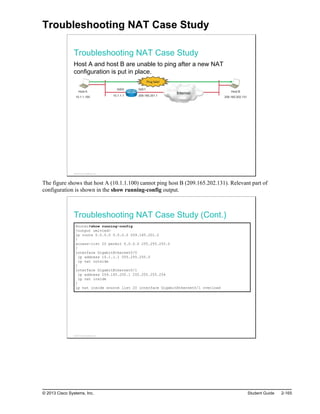


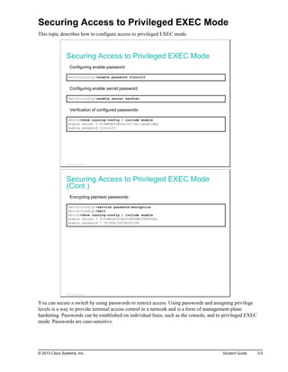
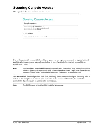
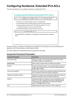
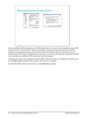
![Securing Remote Access
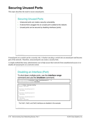
This topic describes how to secure remote access.
Securing Remote Access
Virtual terminal password:
Switch(config)#line vty 0 15
Switch(config-line)#login
Switch(config-line)#password CiScO
EXEC timeout:
Switch(config-line)#exec-timeout 5
© 2013 Cisco Systems, Inc.
Securing Remote Access (Cont.)
Configuring SSH:
Switch(config)#hostname SwitchX
SwitchX(config)#ip domain-name cisco.com
SwitchX(config)#username user1 secret C1sco123
SwitchX(config)#crypto key generate rsa modulus 1024
The name for the keys will be: SwitchX.cisco.com
% The key modulus size is 1024 bits
% Generating 1024 bit RSA keys, keys will be non-exportable...
[OK] (elapsed time was 1 seconds)
SwitchX(config)#line vty 0 15
SwitchX(config-line)#login local
SwitchX(config-line)#transport input ssh
SwitchX(config-line)#exit
SwitchX(config)#ip ssh version 2
© 2013 Cisco Systems, Inc.
The line vty 0 15 command, followed by the login and password subcommands, requires login and
establishes a login password on incoming Telnet sessions.
The login local command can be used to enable password checking on a per-user basis using the username
and secret password that are specified with the username global configuration command. The username
command establishes username authentication with encrypted passwords.
3-8 Interconnecting Cisco Networking Devices, Part 1 © 2013 Cisco Systems, Inc.](https://image.slidesharecdn.com/interconnectingcisconetworkingdevices-220917054712-ee97341f/85/Interconnecting_Cisco_Networking_Devices-pdf-310-320.jpg)
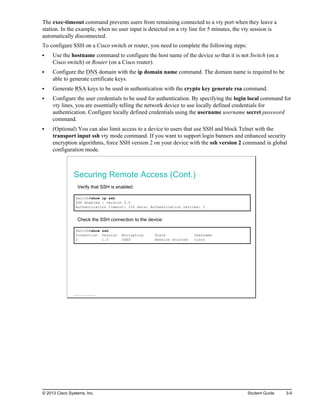
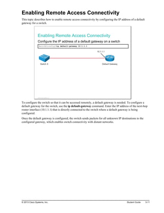


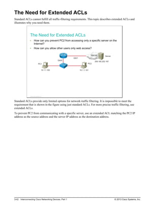
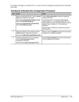
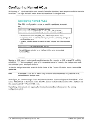
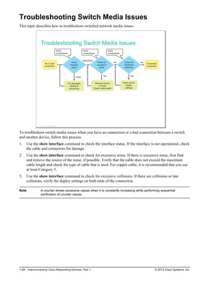
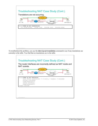
![Configuring NTP
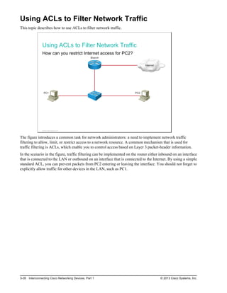
This topic describes how to configure NTP on Cisco devices.
Configuring NTP
Configure the Branch router as the NTP client, which will synchronize its time
with the NTP server.
Branch(config)#ntp server 209.165.201.15
Configure the SW1 switch as the NTP client, which will synchronize its time with
the Branch router.
SW1(config)#ntp server 10.1.1.1
209.165.201.15
10.1.1.0/24
Branch
SW1
NTP Server
.1
NTP Client NTP Client
© 2013 Cisco Systems, Inc.
The figure shows an example configuration scenario. Both router Branch and switch SW1 are configured as
NTP clients using the ntp server ip-address global configuration command. The IP address of the NTP
server is configured.
A Cisco IOS device acting as an NTP client will also respond to received time requests. This enables switch
SW1 to sync directly with router Branch and optimize traffic flows. Alternatively, you could configure
switch SW1 to sync with an external NTP server as well.
Cisco IOS devices can also act as NTP servers. To configure Cisco IOS Software as an NTP master clock to
which peers synchronize themselves, use the ntp master command in global configuration mode:
ntp master [stratum]
Note Use this command with caution. Valid time sources can be easily overridden using this command,
especially if a low stratum number is configured. Configuring multiple devices in the same network with
the ntp master command can cause instability in keeping time if the devices do not agree on the time.
The stratum value is a number from 1 to 15. The lowest stratum value indicates a higher NTP priority. It
also indicates the NTP stratum number that the system will claim.
© 2013 Cisco Systems, Inc. Student Guide 3-33](https://image.slidesharecdn.com/interconnectingcisconetworkingdevices-220917054712-ee97341f/85/Interconnecting_Cisco_Networking_Devices-pdf-335-320.jpg)