This document provides information on combination waste and vent plumbing systems according to the 2021 Uniform Plumbing Code. Key points include:
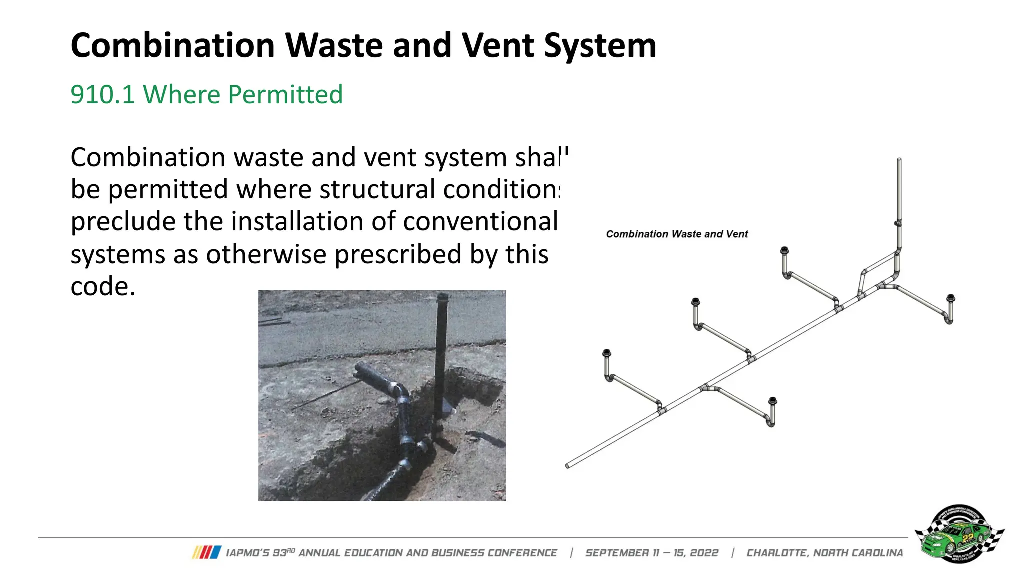
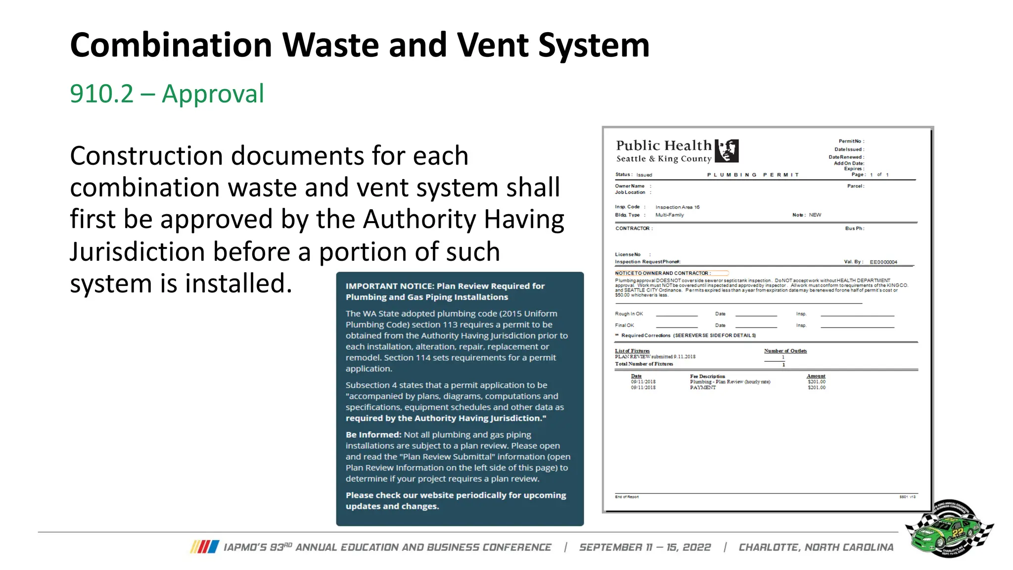
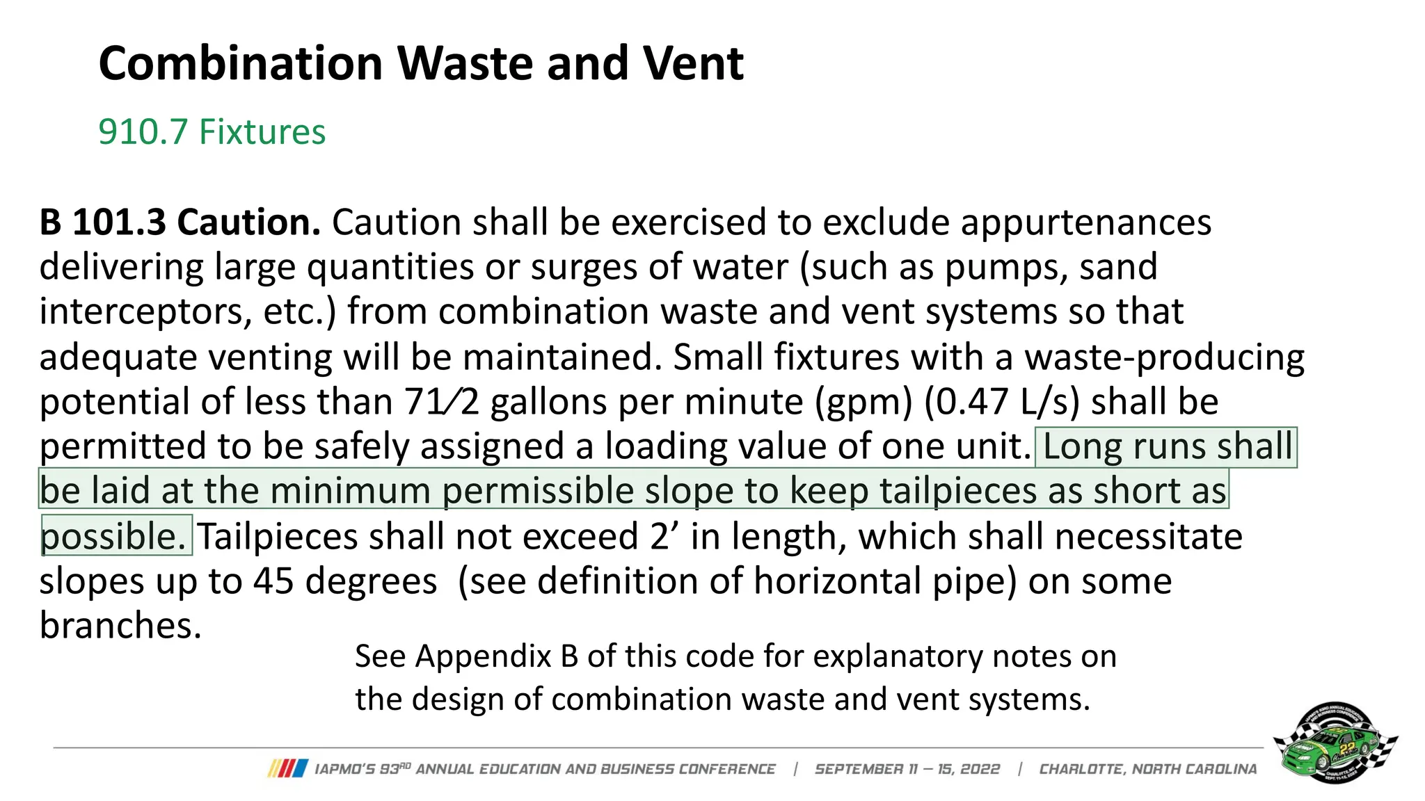
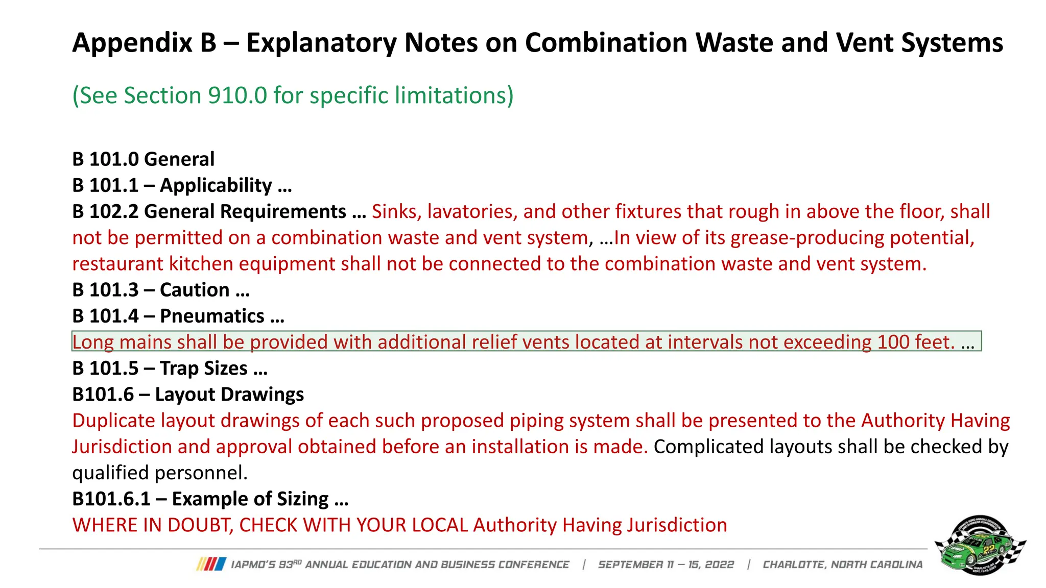
- Combination waste and vent systems can be used where structural conditions prevent conventional venting, and must be approved by the Authority Having Jurisdiction.
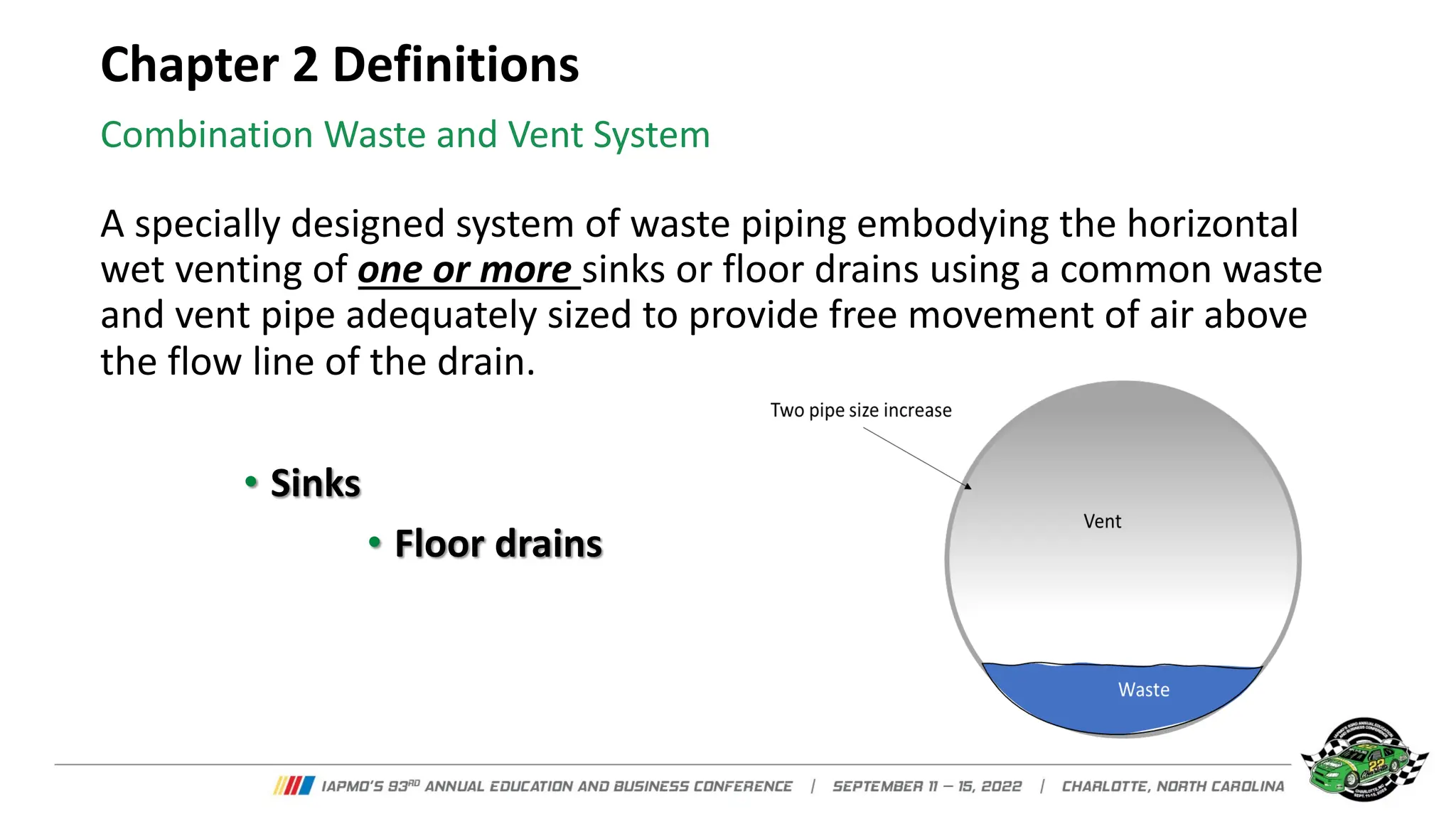
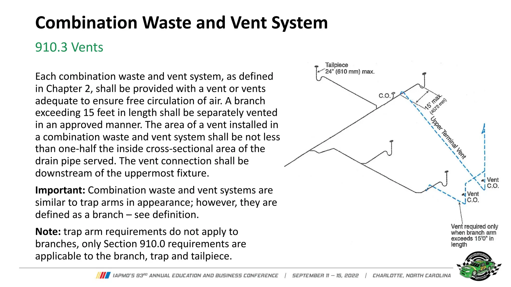
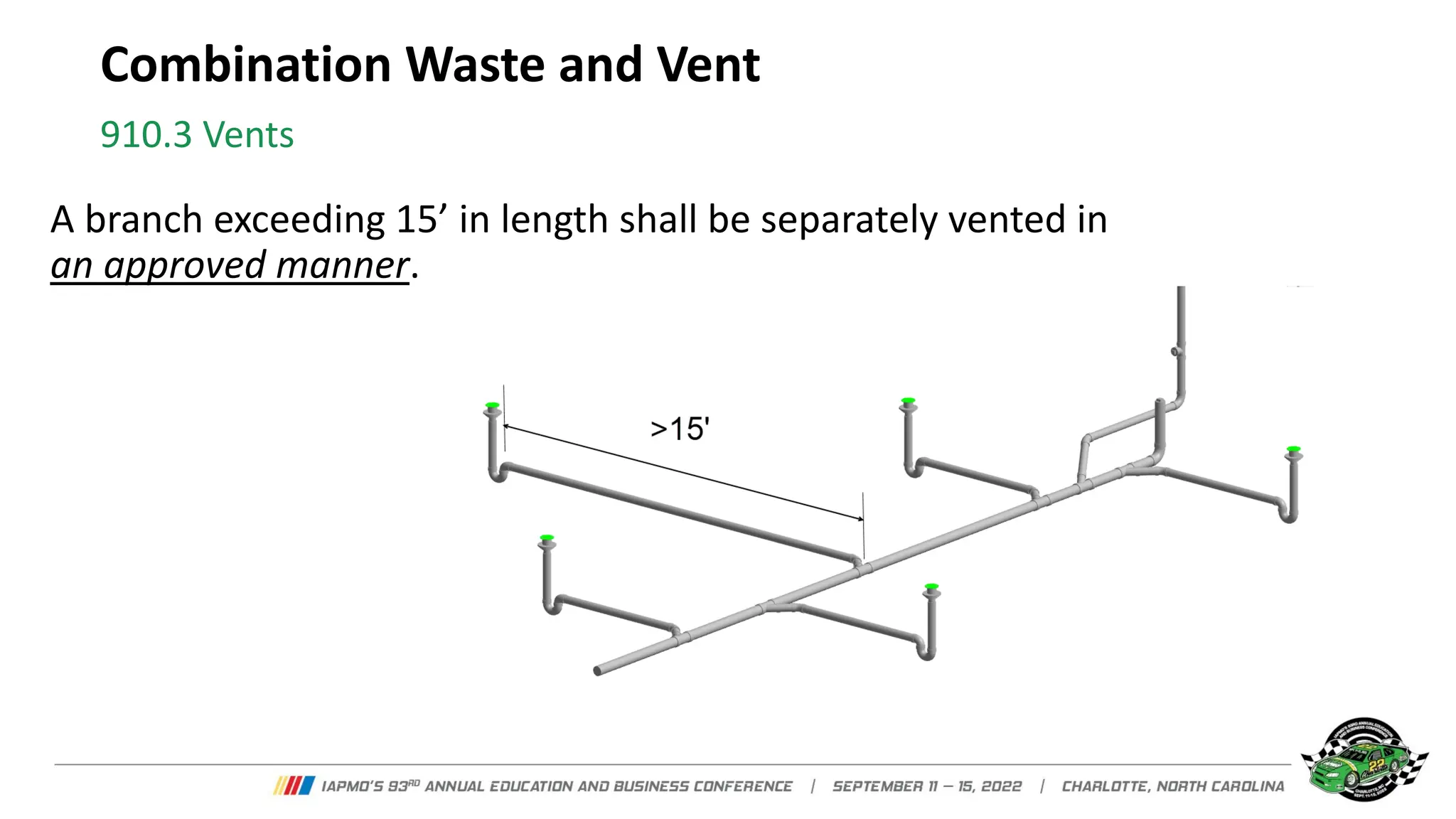
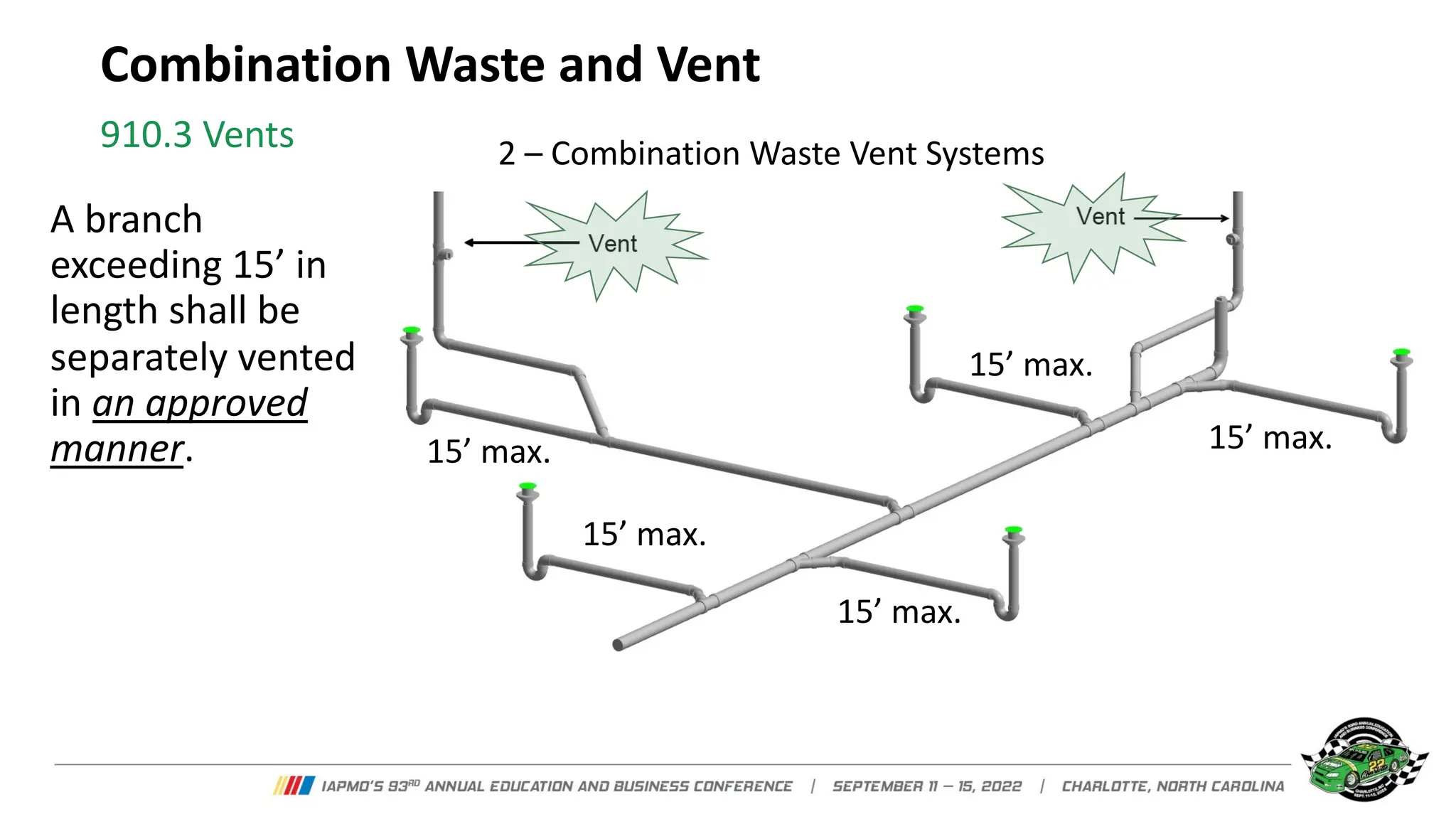
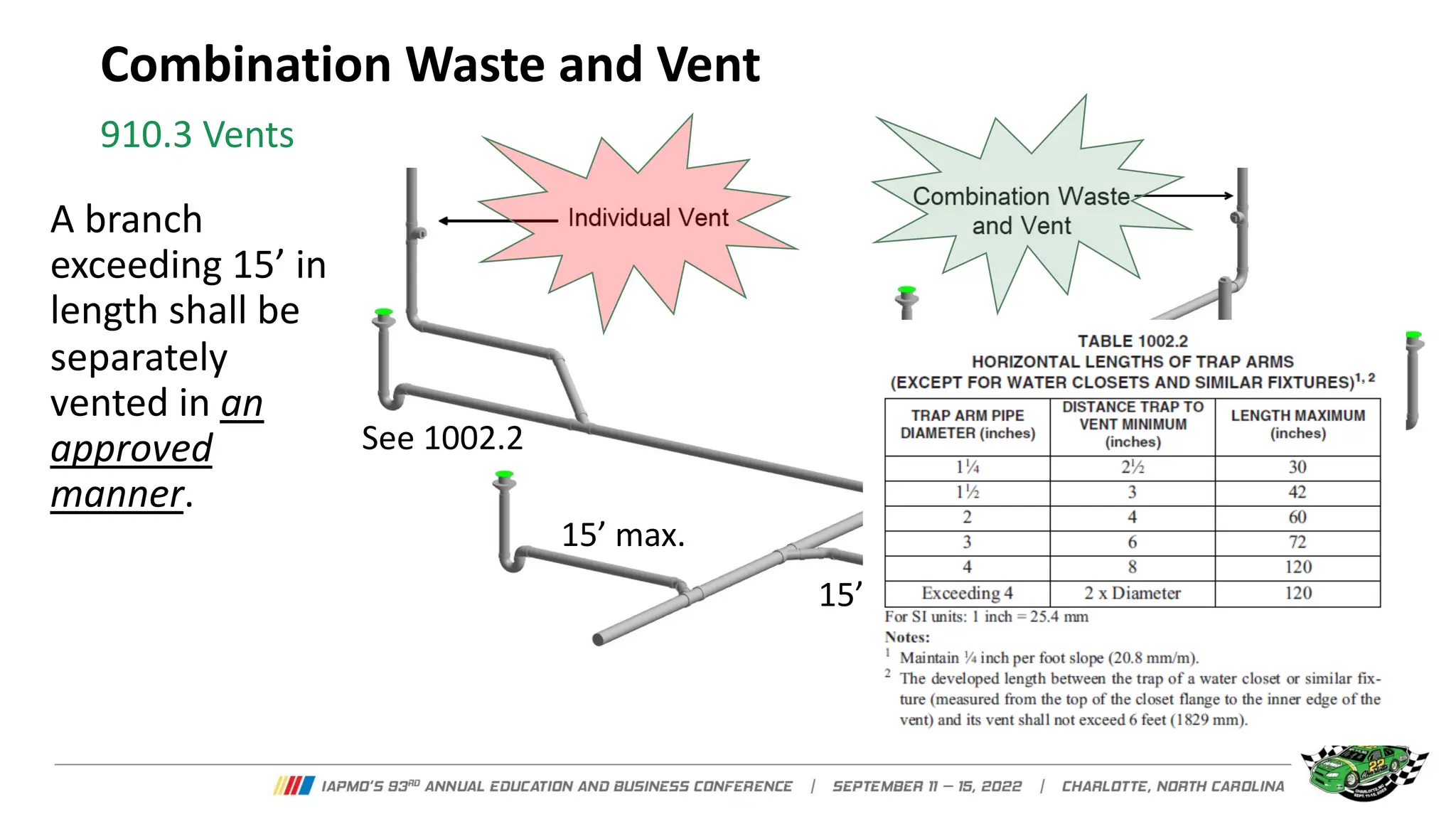
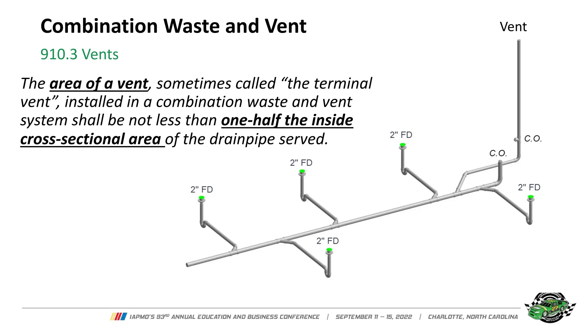
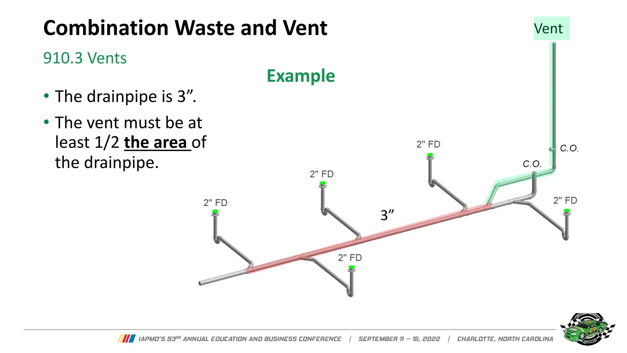
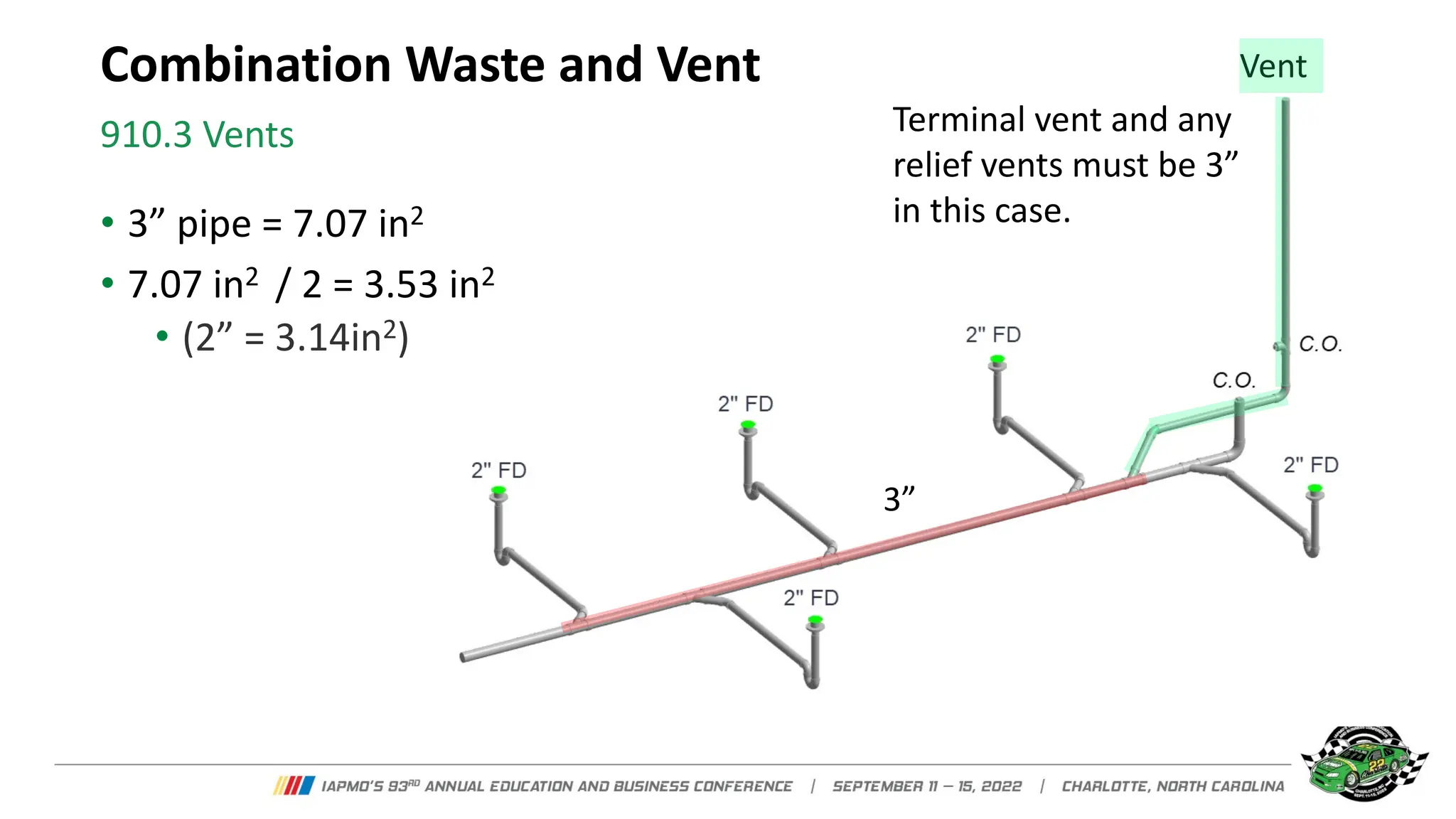
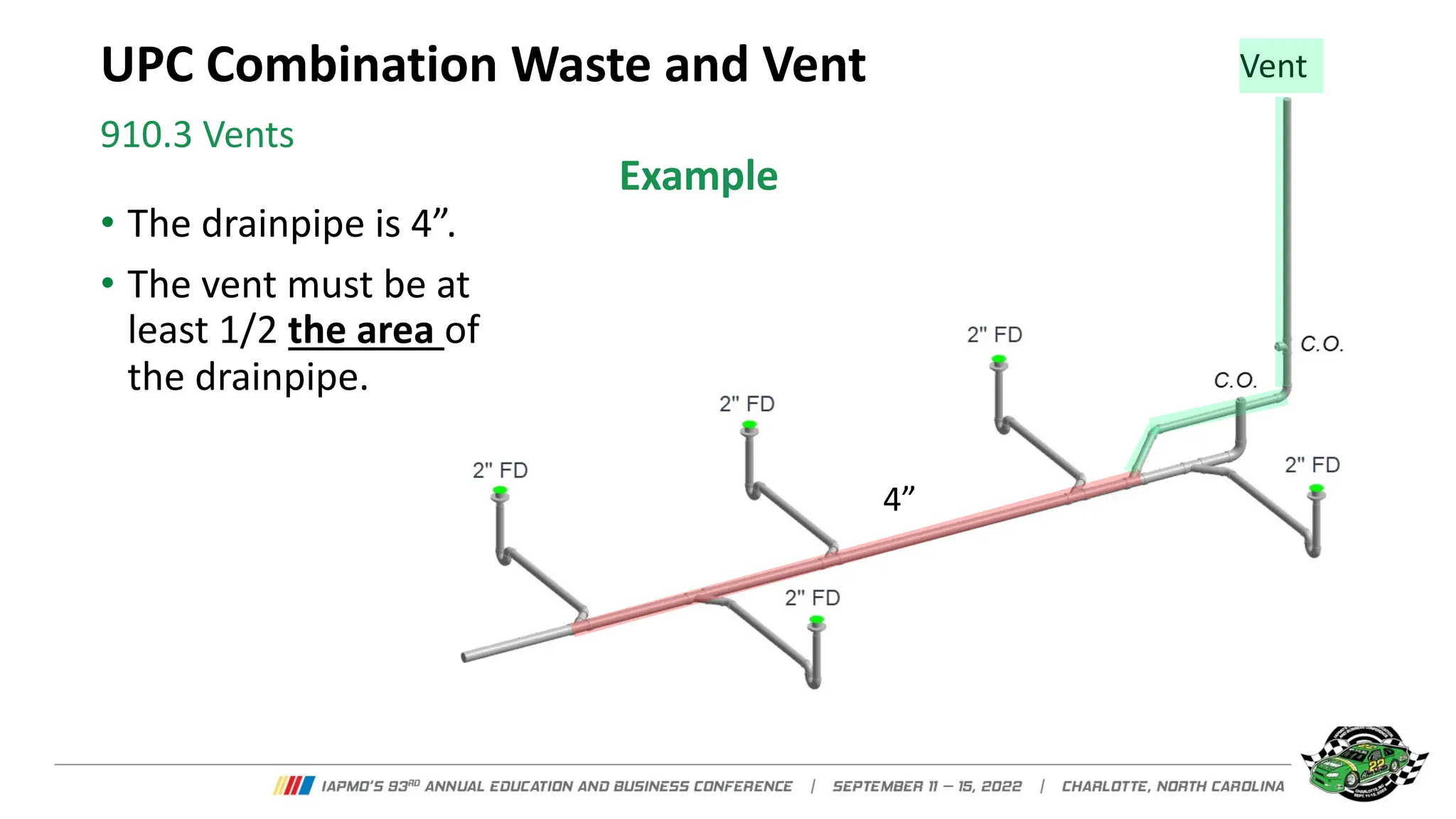
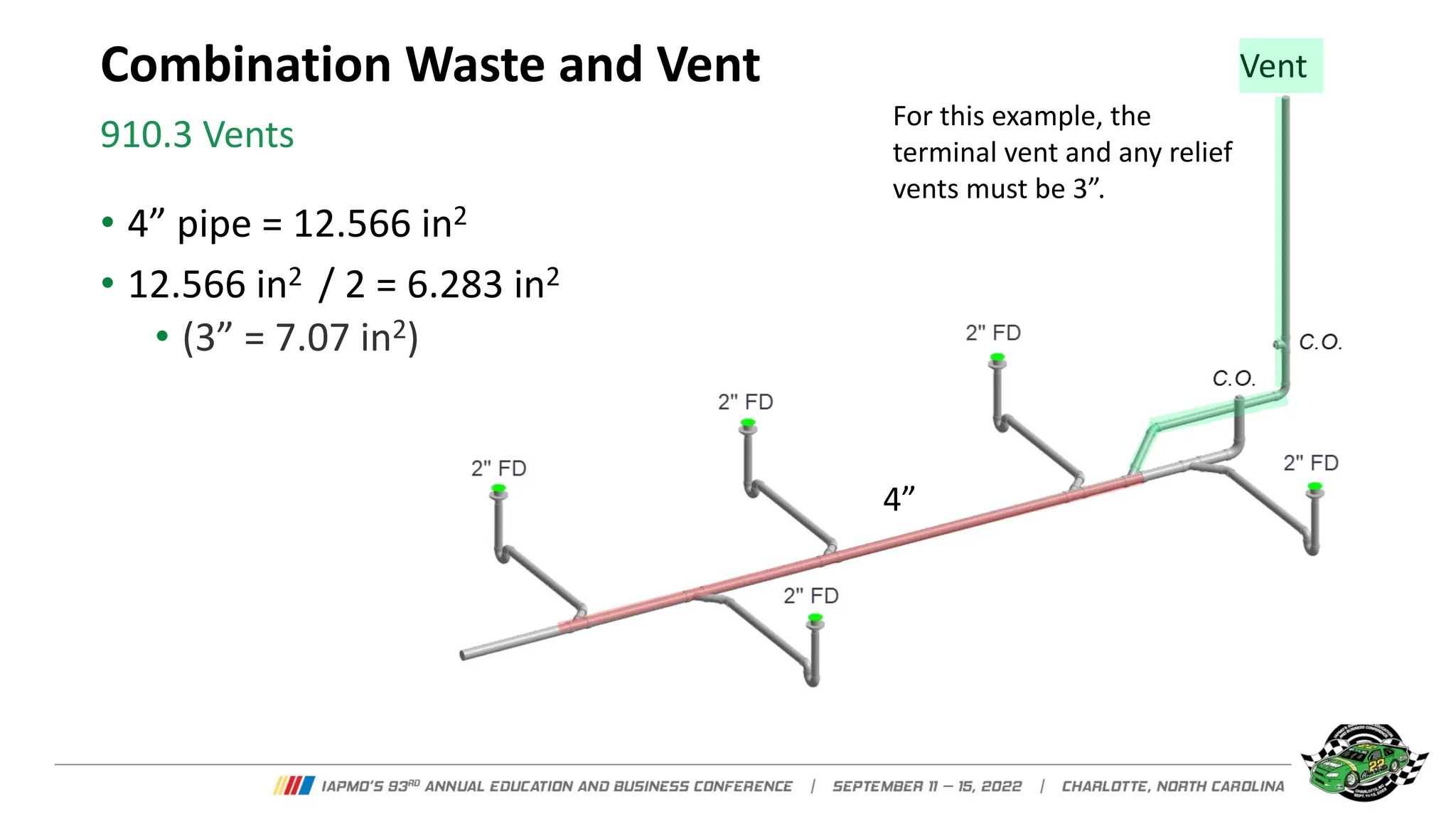
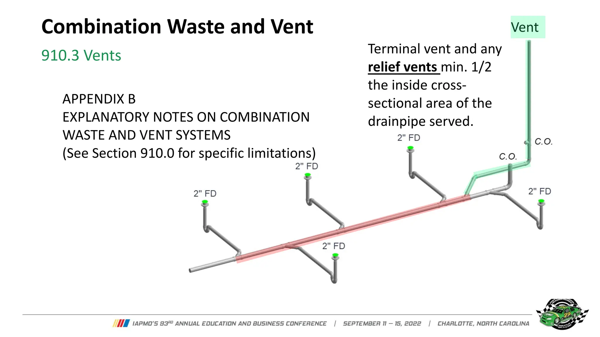
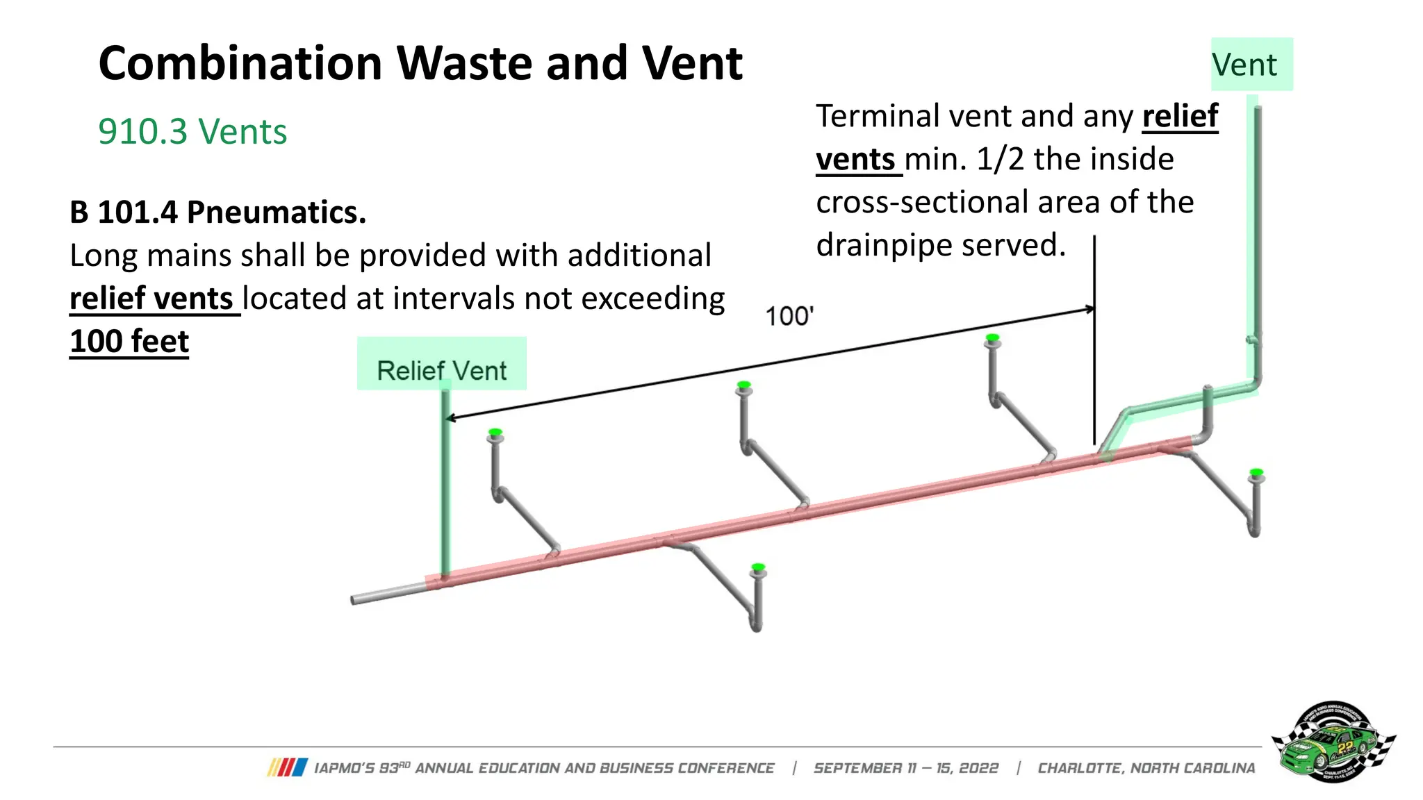
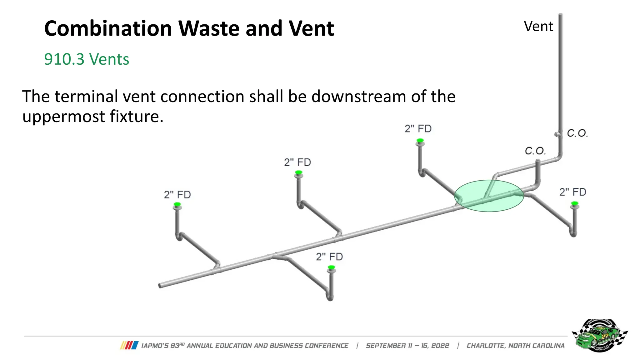
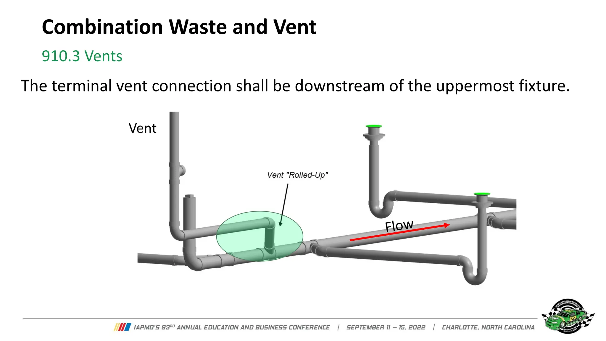
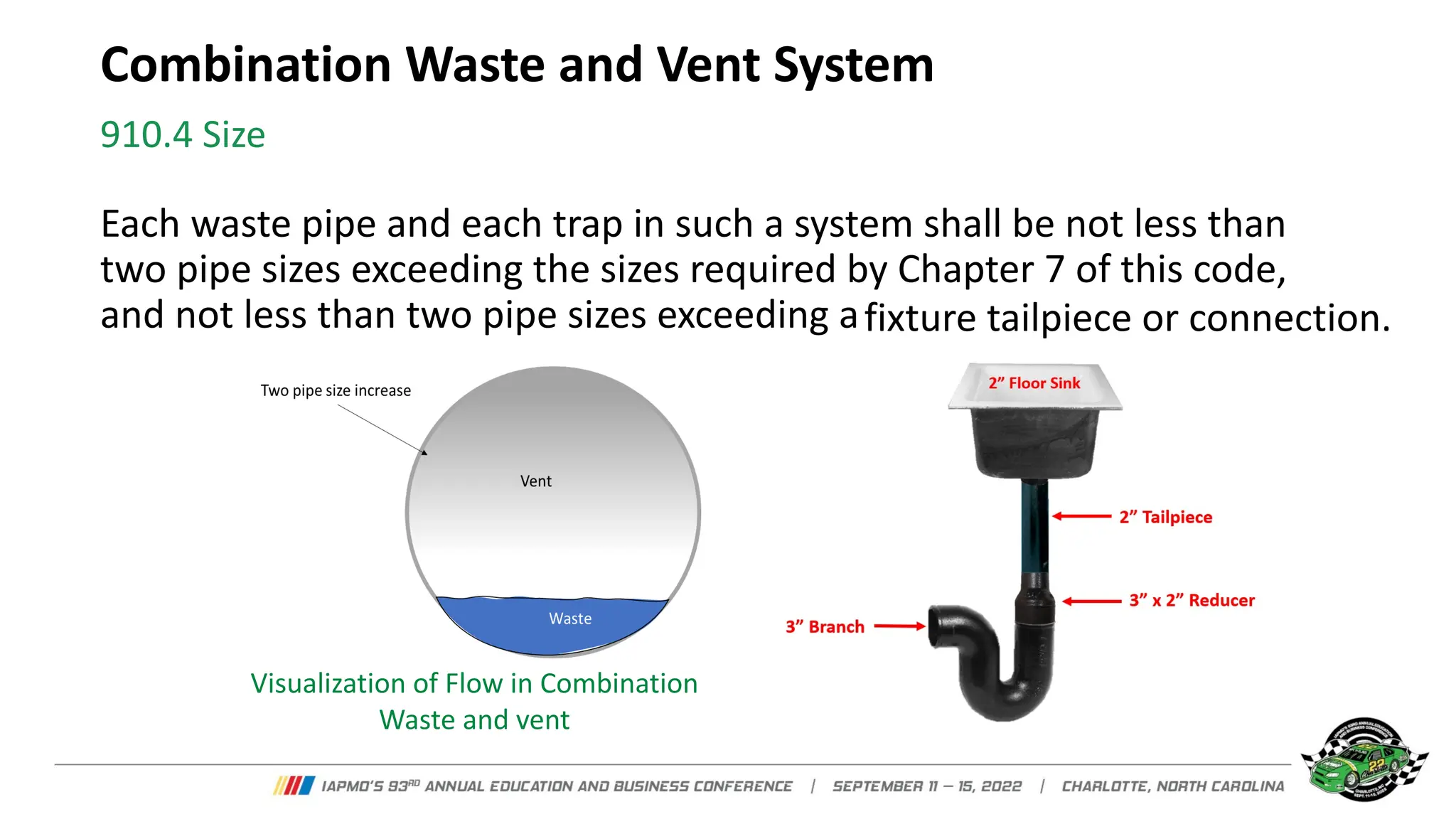
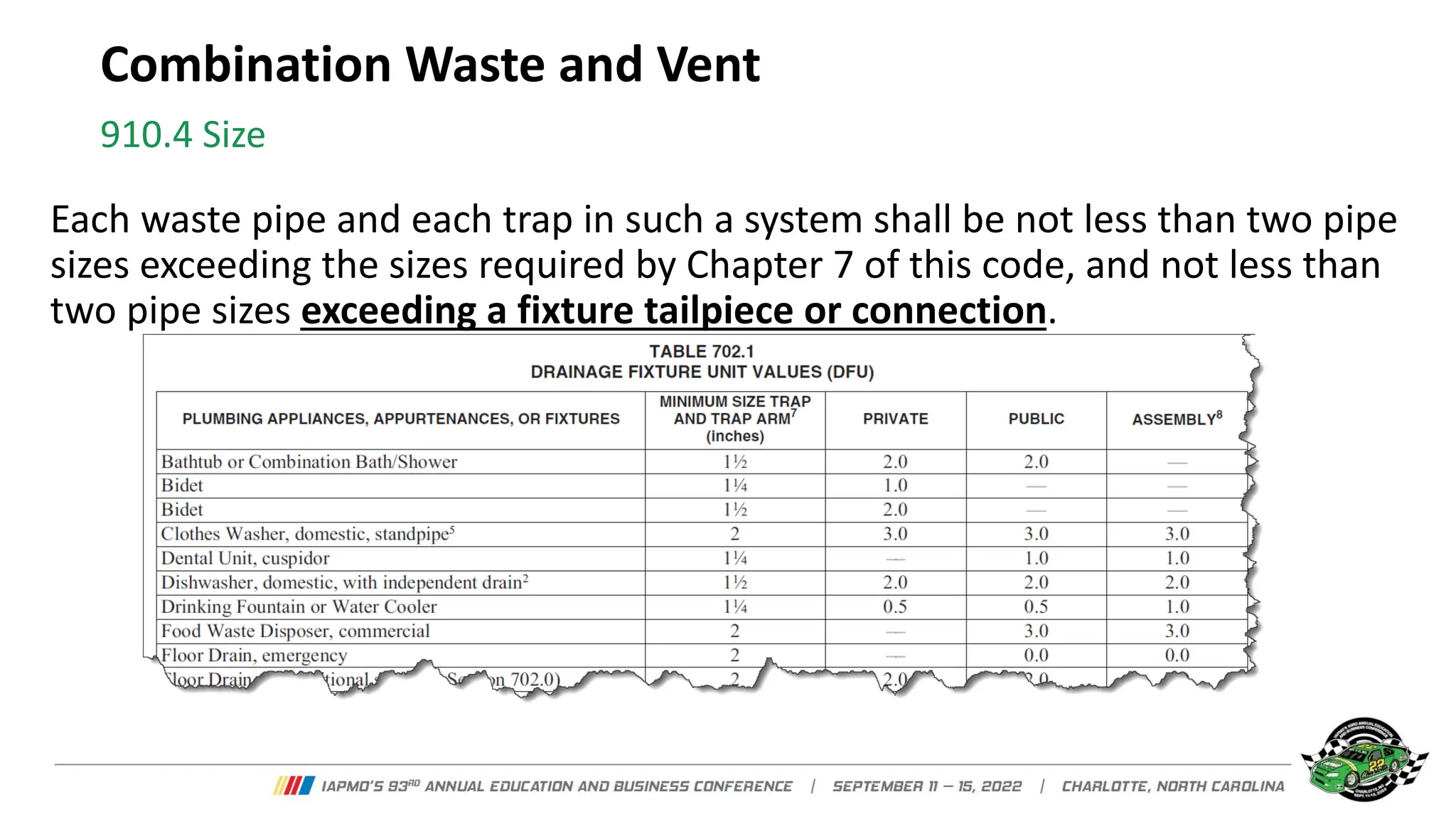
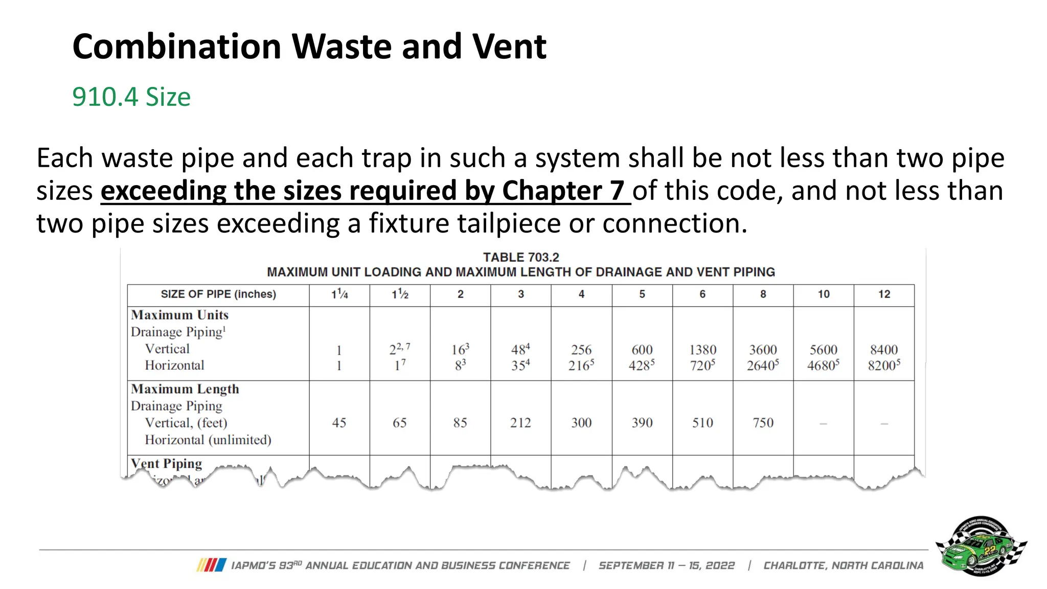
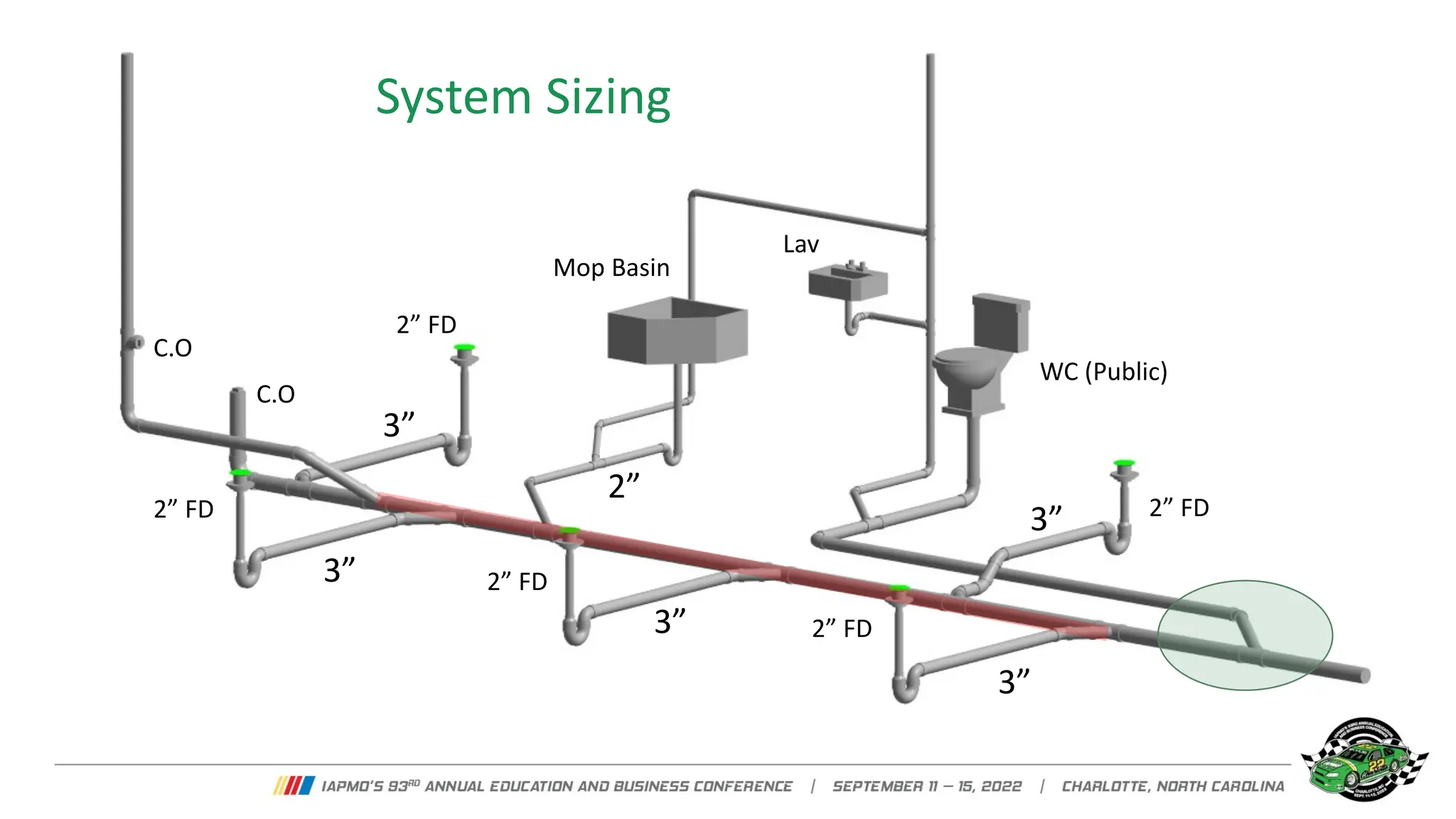
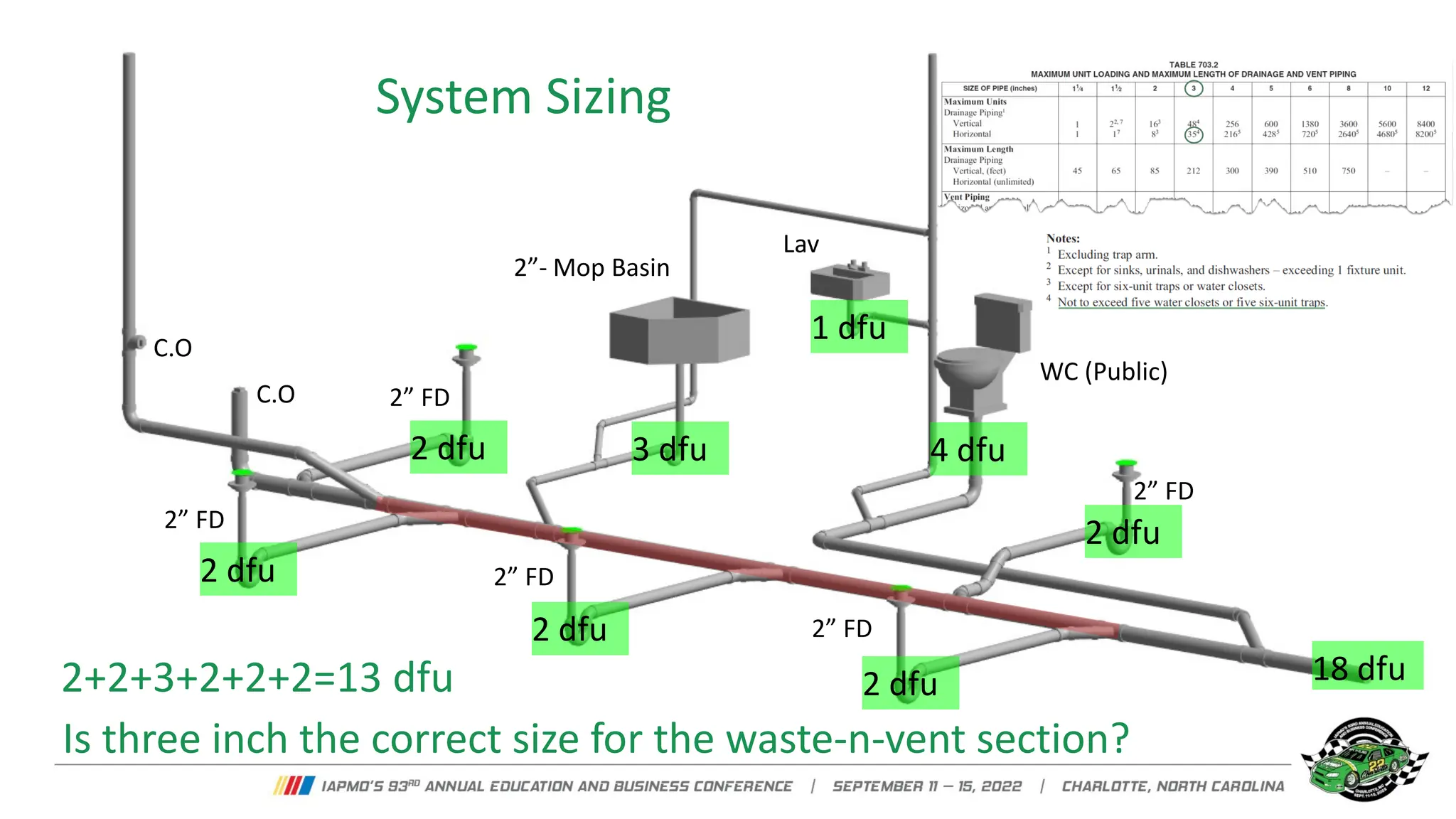
- Each system must have a vent sized to at least half the drain pipe area to ensure air circulation. Branches over 15 feet must have separate vents.
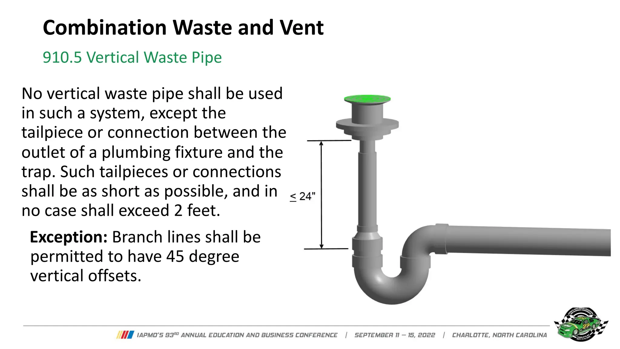
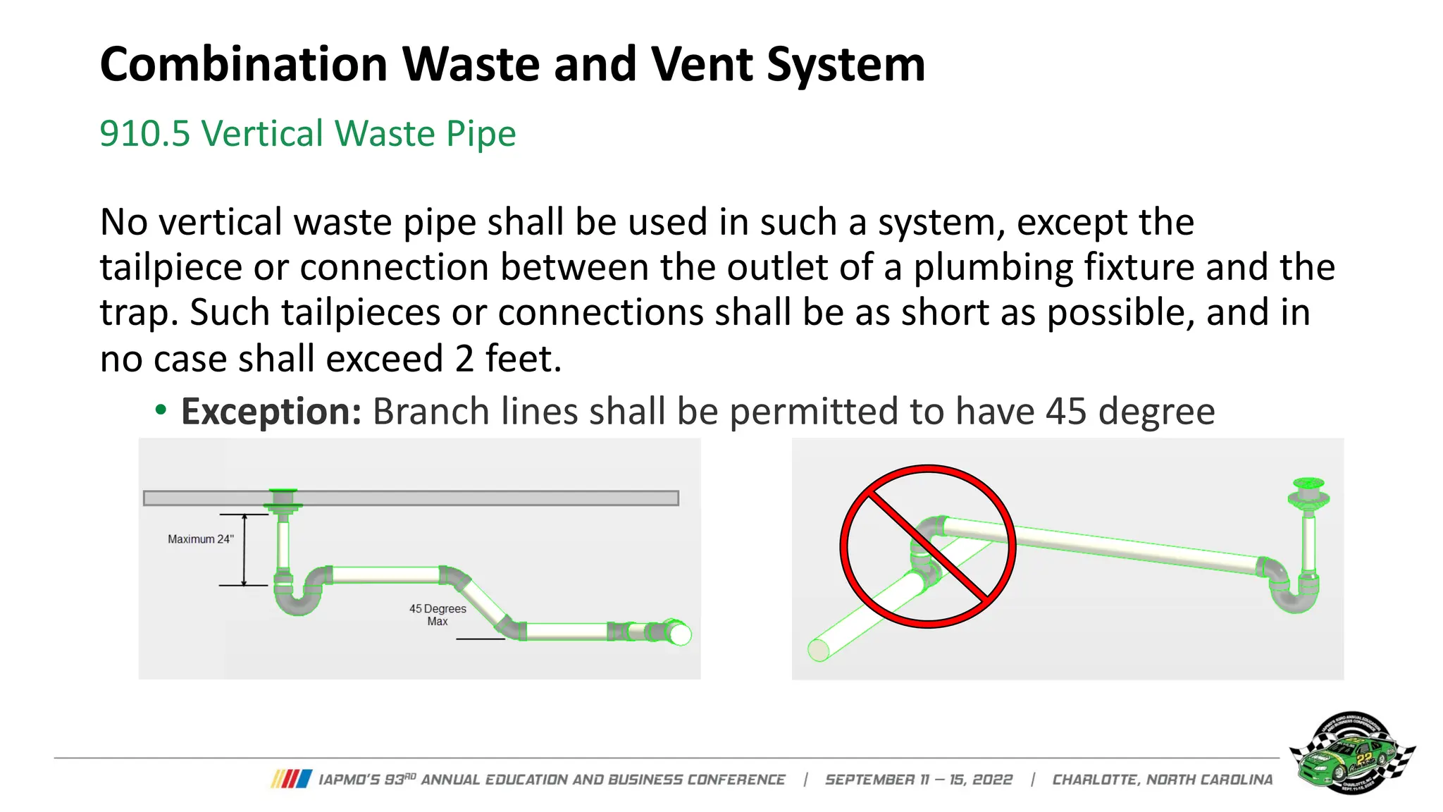
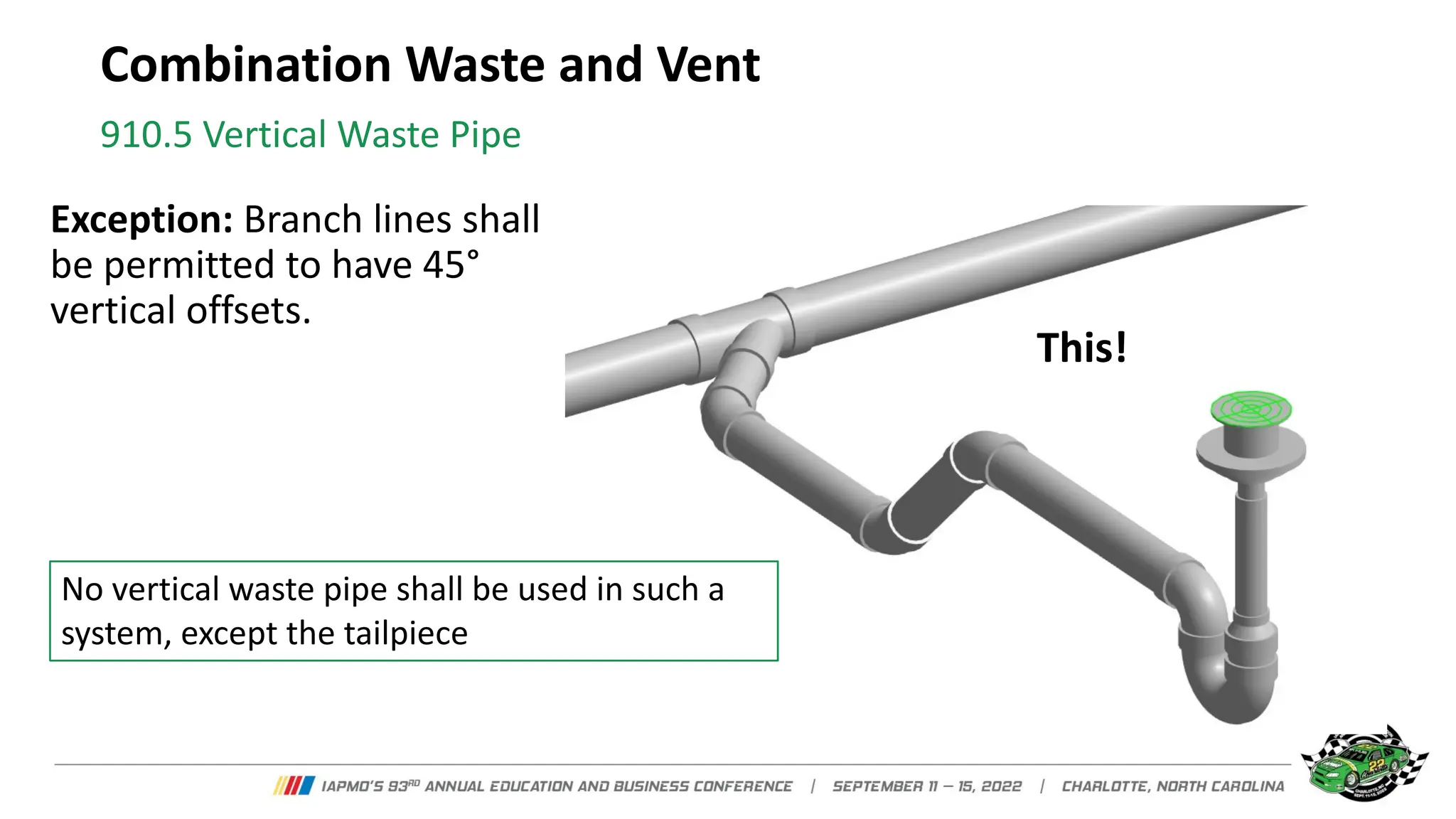
- No vertical waste pipes can be used except short tailpieces from fixtures to traps. Branch lines can have 45 degree offsets.
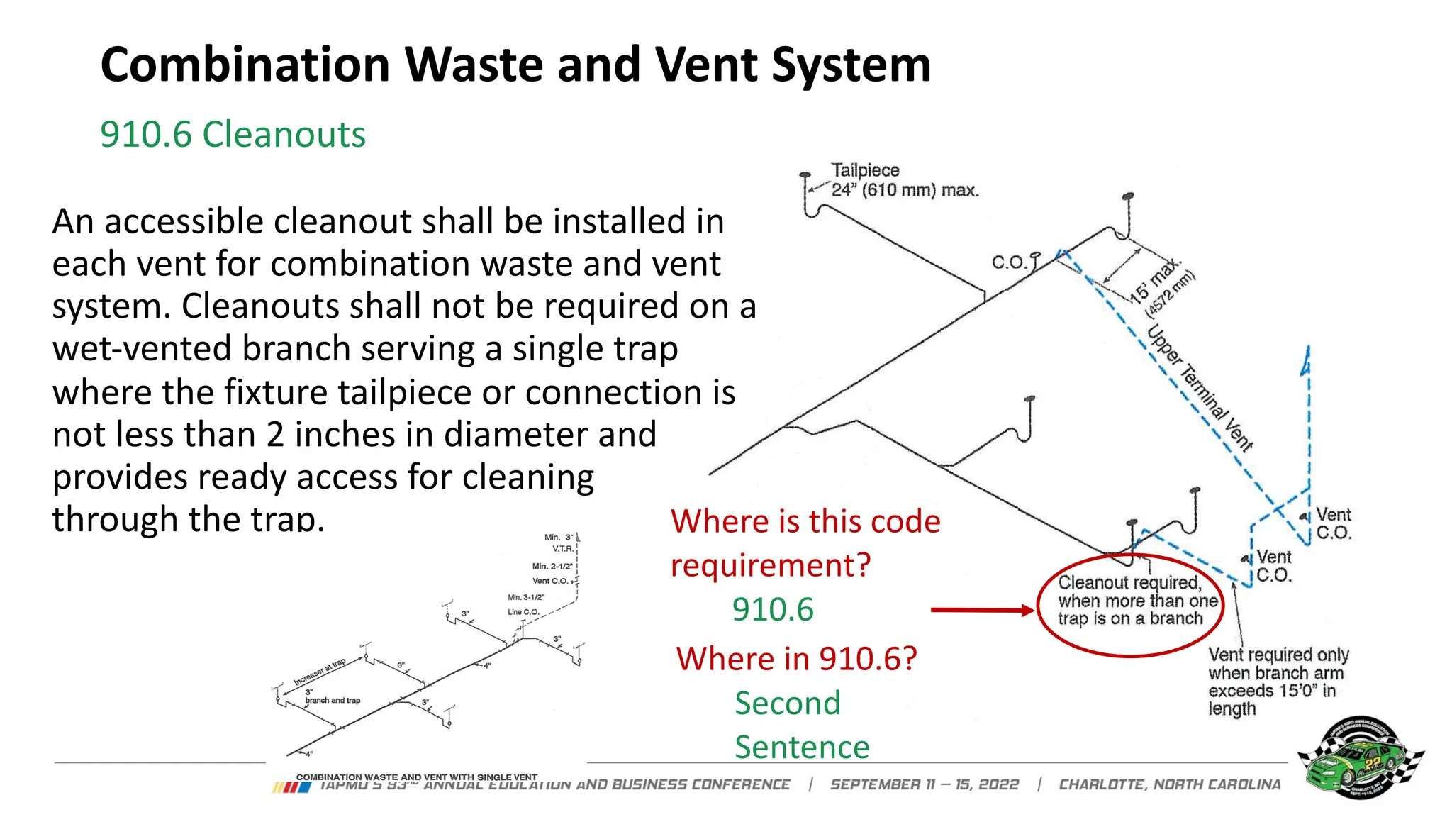
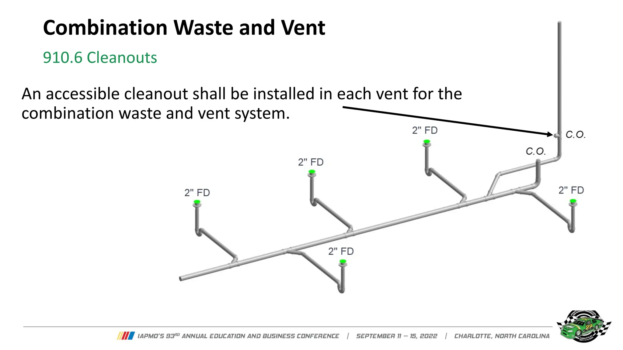
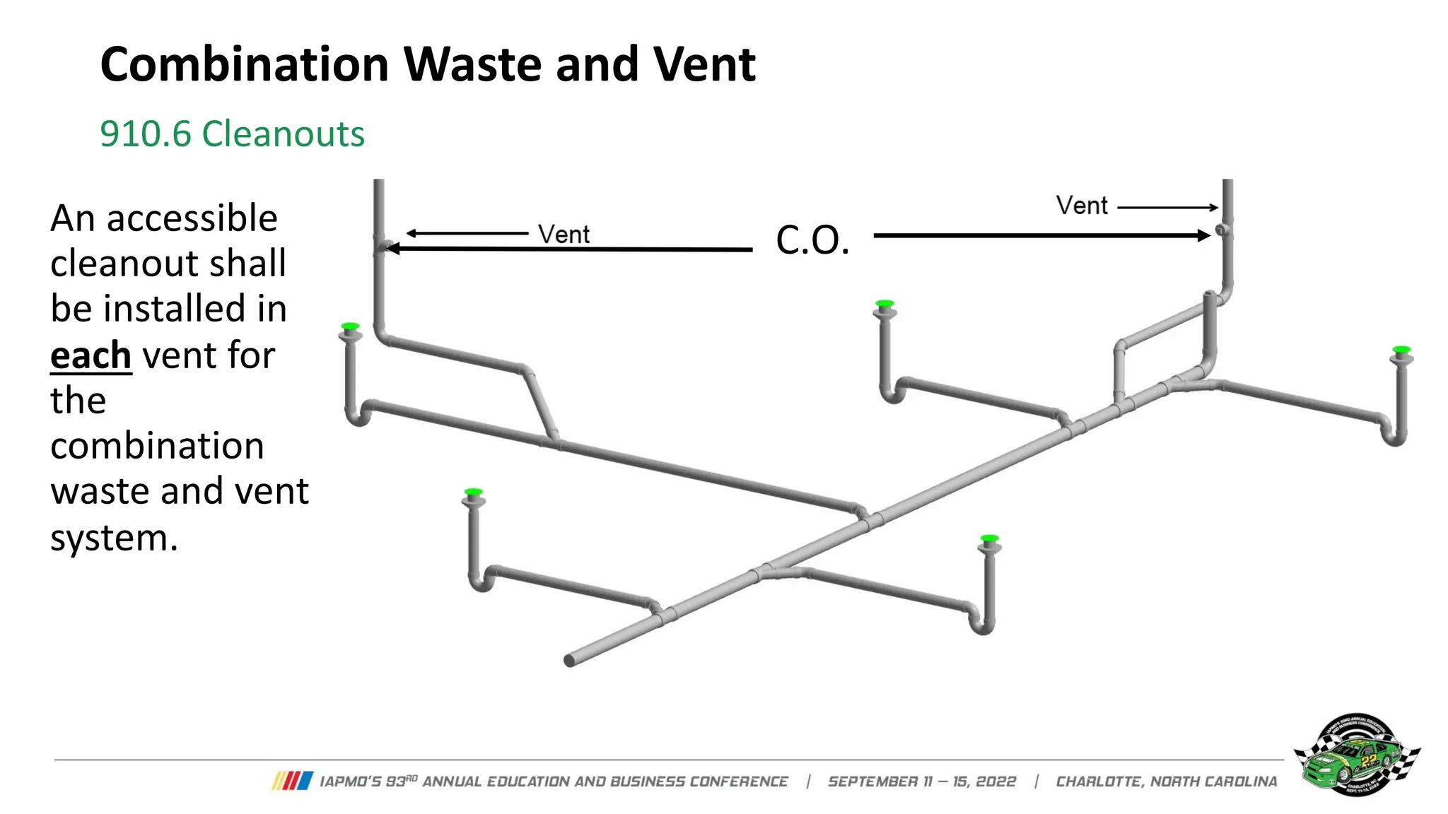
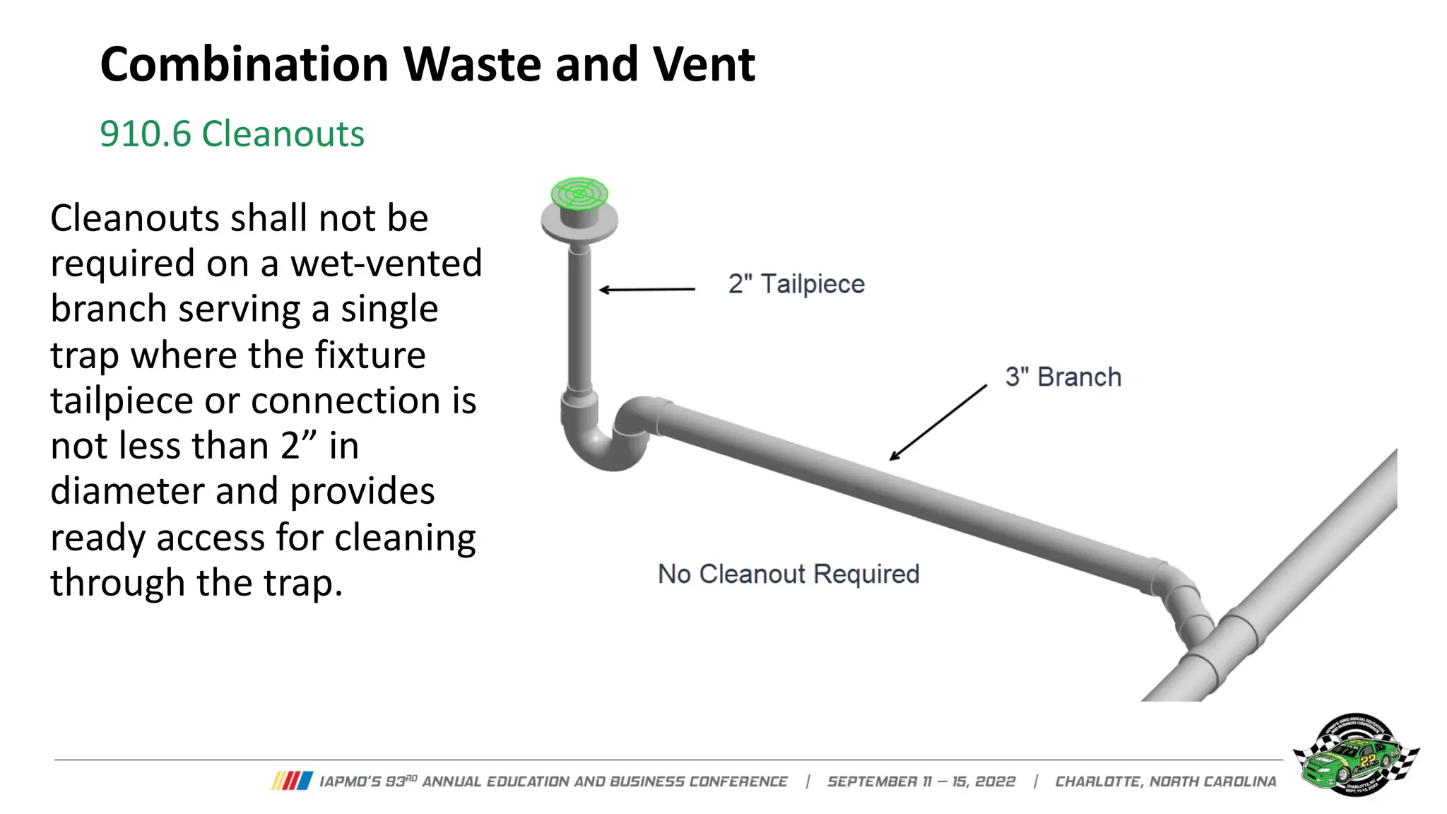
- Cleanouts are required in each vent, except for single trap branches over 2 inches in diameter.