Download to read offline

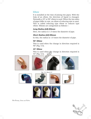
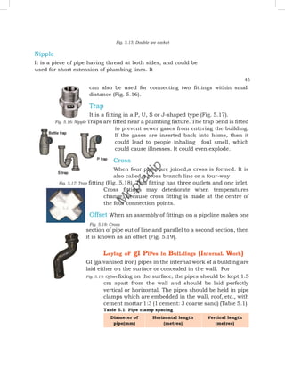
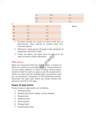
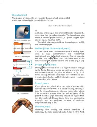


The document discusses various pipe fittings, joints, and valves used in plumbing systems. It describes common pipe fittings like elbows, tees, reducers, and collars that are used to connect pipes or change the pipe direction. Different types of joints are also covered, such as threaded, welded, brazed, soldered, grooved, and flanged joints. Finally, the document outlines various valves including sluice valves, scour valves, air valves, and gate valves that are used to control or stop water flow. Proper selection and installation of fittings, joints, and valves ensures smooth functioning and cost-effectiveness of plumbing systems.


