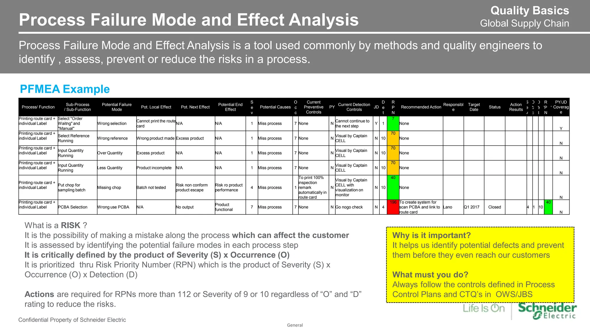
General
Confidential Property of Schneider Electric
PFMEA
Refresher Training – Chennai
General
Confidential Property of Schneider Electric |
• FMEA (failure mode and effects analysis) is a step-by-step approach for
collecting knowledge about possible points of failure in a design,
manufacturing process, product or service
• Failure mode and effects analysis is the process of reviewing as many
components, assemblies, and subsystems as possible to identify
potential failure modes in a system and their causes and effects
• FMEA is a risk management tool. By systematically analyzing failure
modes and their outcomes, organizations can identify and prioritize risks
FMEA ?
• Process failure mode and effects analysis (PFMEA) is part of the larger
failure mode and effects analysis (FMEA) family. PFMEA is a risk
management tool that assesses potential failures of a process. PFMEA
identifies possible failure points in a process, documents their causes, and
effects, suggests corrective actions and action to mitigate risks, and
reduces the likelihood of those causes and effects
General
Process Failure Mode and Effect Analysis
Confidential Property of Schneider Electric
Process Failure Mode and Effect Analysis is a tool used commonly by methods and quality engineers to
identify , assess, prevent or reduce the risks in a process.
PFMEA Example
Quality Basics
Global Supply Chain
Process/ Function
Sub-Process
/ Sub-Function
Potential Failure
Mode
Pot. Local Effect Pot. Next Effect
Potential End
Effect
S
e
v
Potential Causes
O
c
c
Current
Preventive
Controls
PY
Current Detection
Controls
JD
D
e
t
R
P
N
Recommended Action
Responsibl
e
Target
Date
Status
Action
Results
S
e
v
'
O
c
c
'
D
e
t
'
R
P
N
'
PY/JD
Coverag
e
Printing route card +
individual Label
Select "Order
Waitng" and
"Manual"
Wrong selection
Cannot print the route
card
N/A N/A 1 Miss process 7 None N
Cannot continue to
the next step
Y 1
7
None
Y
Printing route card +
individual Label
Select Reference
Running
Wrong reference Wrong product made Excess product N/A 1 Miss process 7 None N
Visual by Captain
CELL
N 10
70
None
N
Printing route card +
individual Label
Input Quantity
Running
Over Quantity Excess product N/A N/A 1 Miss process 7 None N
Visual by Captain
CELL
N 10
70
None
N
Printing route card +
individual Label
Input Quantity
Running
Less Quantity Product incomplete N/A N/A 1 Miss process 7 None N
Visual by Captain
CELL
N 10
70
None
N
Printing route card +
individual Label
Put chop for
sampling batch
Missing chop Batch not tested
Risk non conform
product escape
Risk ro product
performance
4 Miss process 1
To print 100%
inspection
remark
automatically in
route card
N
Visual by Captain
CELL with
visualization on
monitor
N 10
40
None
N
Printing route card +
individual Label PCBA Selection Wrong use PCBA N/A No output
Product
functional
7 Miss process 7 None N Go nogo check N 4
196 To create system for
scan PCBA and link to
route card
Lano Q1 2017 Closed 4 1 10
40
N
What is a RISK ?
It is the possibility of making a mistake along the process which can affect the customer
It is assessed by identifying the potential failure modes in each process step
It is critically defined by the product of Severity (S) x Occurrence (O)
It is prioritized thru Risk Priority Number (RPN) which is the product of Severity (S) x
Occurrence (O) x Detection (D)
Actions are required for RPNs more than 112 or Severity of 9 or 10 regardless of “O” and “D”
rating to reduce the risks.
Why is it important?
It helps us identify potential defects and prevent
them before they even reach our customers
What must you do?
Always follow the controls defined in Process
Control Plans and CTQ’s in OWS/JBS
General
Process Flow Diagram
Confidential Property of Schneider Electric
Process flow diagram (PFD) is a picture of separate steps of a process in a sequential order. Elements that
may be included are: sequence of actions, decisions that must be made, time involved at each step and/or
process measurements.
Standard Flowchart Symbols
PROCESS
Any kind of
processing
function
TERMINATOR
Start or End of
process flow
DECISION
A decision or
switching type
function
CONNECTOR LINES
Used to describe the logic
flow between symbols.
Arrowheads are used when
the flow is to the left or up
ON-PAGE REFERENCE
Cross-reference within the
same page of the
flowchart
OFF-PAGE REFERENCE
Cross-reference to
another page of the flow
chart
Quality Basics
Global Supply Chain
General
Process Control Plan
Confidential Property of Schneider Electric
Process Control Plan (PCP) is a method for documenting the functional elements of quality control in a
manufacturing process that are to be implemented in order to assure that quality standards are met for a
particular product. It is built from the Product Quality Control Plan and PFMEA analysis.
Quality Basics
Global Supply Chain
1. Process Identification
- records all the process
steps linked to the
process flow diagram
Plant: SENSOR Process Control Plan
Process:
Product: XS156
Index Date
6-May-17
28-Jul-17
Cutting and soldering diameter 08
Temperature
Solder
375 - 385 °C
Temp
Calibration
Critical Manual Thermocouple 1 per Shift LI
Form 2020106 -
102 00 Soldering
Cell 1
Adjust the
temperature,
change the iron tip
or call technician
Orientation of Coil
Coil must in the right
orientation
Major Poka Yoke Jig 100% 100% Operator Scrap
Orientation of LED
LED must bend to the right
position
Major Visual Jig 100% 100% Operator Scrap OWS: 72247
Continuity (Functional --
> Go No Go Test)
Product is able to detect
object and LED able to
switch ON and OFF
Major Jidoka
Go No Go
Tester
100% 100% Operator Scrap OWS: 72247
Temperature +70 degree +1/-3 Major Manual Thermocouple 1 every 6 months Metrology
Adjust the
temperature, or call
technician
Duration 1 Hour Major Manual Stop watch 100% 100% Operator Route Card call supervisor OWS: 72247
Objet Created by Verified by Comments
Add MRKP from PQCP for Waterproof flow Lano Lano
Manufacturing Process identification Specification Measurements Sampling Strategy Action and Documention
Change QRD number ( & modify content) on first filling and Secmer due to Low pressure issue
Frequency
Who/What
Measures
Where recorded
Reaction Plan
(Decision Rule)
Instruction
Limits
Mandatory
Requirements
for Key Process
Intrinsic Criticity
Type of inspection or
control
Mean/Tool Dummy
Sample
Size
Step Operation
Machine / Station
/ Tool
Type:
Manual
Automatic
Semi-automatic
Product Parameter
Process
Parameter
4
Cutting and
soldering
diameter 08
Cutting and
soldering
diameter 08
Manual
Oven
4. Action and
Documentation-
finally what
should happen
when the step
goes out of
control
4 KEY ELEMENTS OF PCP
2. Specification
Measurements- a
detailed description of
what has to be
Controlled
3. Sampling
Strategy- how
the step will be
controlled
Why is it important?
It defines the process controls in place and their
criticality to detect and prevent occurrence of defects
along the process
What must you do?
Consistently follow the controls defined in Process
Control Plans
General
Confidential Property of Schneider Electric |
General
Confidential Property of Schneider Electric |
General
Confidential Property of Schneider Electric |
General
Confidential Property of Schneider Electric |
General
Confidential Property of Schneider Electric |
General
Confidential Property of Schneider Electric |
General
Confidential Property of Schneider Electric |
General
Confidential Property of Schneider Electric |
General
Confidential Property of Schneider Electric |
General
Confidential Property of Schneider Electric |
General
Confidential Property of Schneider Electric |
General
Confidential Property of Schneider Electric |
General
Confidential Property of Schneider Electric |
General
Confidential Property of Schneider Electric |
General
Confidential Property of Schneider Electric |
General
Confidential Property of Schneider Electric |
General
Confidential Property of Schneider Electric |
General
Confidential Property of Schneider Electric |
General
Confidential Property of Schneider Electric |
General
Confidential Property of Schneider Electric |
General
Page 26
Confidential Property of Schneider Electric |
General
Page 27
Confidential Property of Schneider Electric |
General
Page 28
Confidential Property of Schneider Electric |
Thank you!

PFMEA refresher training for the beginners to help them

  • 1.
    General Confidential Property ofSchneider Electric PFMEA Refresher Training – Chennai
  • 2.
    General Confidential Property ofSchneider Electric | • FMEA (failure mode and effects analysis) is a step-by-step approach for collecting knowledge about possible points of failure in a design, manufacturing process, product or service • Failure mode and effects analysis is the process of reviewing as many components, assemblies, and subsystems as possible to identify potential failure modes in a system and their causes and effects • FMEA is a risk management tool. By systematically analyzing failure modes and their outcomes, organizations can identify and prioritize risks FMEA ? • Process failure mode and effects analysis (PFMEA) is part of the larger failure mode and effects analysis (FMEA) family. PFMEA is a risk management tool that assesses potential failures of a process. PFMEA identifies possible failure points in a process, documents their causes, and effects, suggests corrective actions and action to mitigate risks, and reduces the likelihood of those causes and effects
  • 3.
    General Process Failure Modeand Effect Analysis Confidential Property of Schneider Electric Process Failure Mode and Effect Analysis is a tool used commonly by methods and quality engineers to identify , assess, prevent or reduce the risks in a process. PFMEA Example Quality Basics Global Supply Chain Process/ Function Sub-Process / Sub-Function Potential Failure Mode Pot. Local Effect Pot. Next Effect Potential End Effect S e v Potential Causes O c c Current Preventive Controls PY Current Detection Controls JD D e t R P N Recommended Action Responsibl e Target Date Status Action Results S e v ' O c c ' D e t ' R P N ' PY/JD Coverag e Printing route card + individual Label Select "Order Waitng" and "Manual" Wrong selection Cannot print the route card N/A N/A 1 Miss process 7 None N Cannot continue to the next step Y 1 7 None Y Printing route card + individual Label Select Reference Running Wrong reference Wrong product made Excess product N/A 1 Miss process 7 None N Visual by Captain CELL N 10 70 None N Printing route card + individual Label Input Quantity Running Over Quantity Excess product N/A N/A 1 Miss process 7 None N Visual by Captain CELL N 10 70 None N Printing route card + individual Label Input Quantity Running Less Quantity Product incomplete N/A N/A 1 Miss process 7 None N Visual by Captain CELL N 10 70 None N Printing route card + individual Label Put chop for sampling batch Missing chop Batch not tested Risk non conform product escape Risk ro product performance 4 Miss process 1 To print 100% inspection remark automatically in route card N Visual by Captain CELL with visualization on monitor N 10 40 None N Printing route card + individual Label PCBA Selection Wrong use PCBA N/A No output Product functional 7 Miss process 7 None N Go nogo check N 4 196 To create system for scan PCBA and link to route card Lano Q1 2017 Closed 4 1 10 40 N What is a RISK ? It is the possibility of making a mistake along the process which can affect the customer It is assessed by identifying the potential failure modes in each process step It is critically defined by the product of Severity (S) x Occurrence (O) It is prioritized thru Risk Priority Number (RPN) which is the product of Severity (S) x Occurrence (O) x Detection (D) Actions are required for RPNs more than 112 or Severity of 9 or 10 regardless of “O” and “D” rating to reduce the risks. Why is it important? It helps us identify potential defects and prevent them before they even reach our customers What must you do? Always follow the controls defined in Process Control Plans and CTQ’s in OWS/JBS
  • 4.
    General Process Flow Diagram ConfidentialProperty of Schneider Electric Process flow diagram (PFD) is a picture of separate steps of a process in a sequential order. Elements that may be included are: sequence of actions, decisions that must be made, time involved at each step and/or process measurements. Standard Flowchart Symbols PROCESS Any kind of processing function TERMINATOR Start or End of process flow DECISION A decision or switching type function CONNECTOR LINES Used to describe the logic flow between symbols. Arrowheads are used when the flow is to the left or up ON-PAGE REFERENCE Cross-reference within the same page of the flowchart OFF-PAGE REFERENCE Cross-reference to another page of the flow chart Quality Basics Global Supply Chain
  • 5.
    General Process Control Plan ConfidentialProperty of Schneider Electric Process Control Plan (PCP) is a method for documenting the functional elements of quality control in a manufacturing process that are to be implemented in order to assure that quality standards are met for a particular product. It is built from the Product Quality Control Plan and PFMEA analysis. Quality Basics Global Supply Chain 1. Process Identification - records all the process steps linked to the process flow diagram Plant: SENSOR Process Control Plan Process: Product: XS156 Index Date 6-May-17 28-Jul-17 Cutting and soldering diameter 08 Temperature Solder 375 - 385 °C Temp Calibration Critical Manual Thermocouple 1 per Shift LI Form 2020106 - 102 00 Soldering Cell 1 Adjust the temperature, change the iron tip or call technician Orientation of Coil Coil must in the right orientation Major Poka Yoke Jig 100% 100% Operator Scrap Orientation of LED LED must bend to the right position Major Visual Jig 100% 100% Operator Scrap OWS: 72247 Continuity (Functional -- > Go No Go Test) Product is able to detect object and LED able to switch ON and OFF Major Jidoka Go No Go Tester 100% 100% Operator Scrap OWS: 72247 Temperature +70 degree +1/-3 Major Manual Thermocouple 1 every 6 months Metrology Adjust the temperature, or call technician Duration 1 Hour Major Manual Stop watch 100% 100% Operator Route Card call supervisor OWS: 72247 Objet Created by Verified by Comments Add MRKP from PQCP for Waterproof flow Lano Lano Manufacturing Process identification Specification Measurements Sampling Strategy Action and Documention Change QRD number ( & modify content) on first filling and Secmer due to Low pressure issue Frequency Who/What Measures Where recorded Reaction Plan (Decision Rule) Instruction Limits Mandatory Requirements for Key Process Intrinsic Criticity Type of inspection or control Mean/Tool Dummy Sample Size Step Operation Machine / Station / Tool Type: Manual Automatic Semi-automatic Product Parameter Process Parameter 4 Cutting and soldering diameter 08 Cutting and soldering diameter 08 Manual Oven 4. Action and Documentation- finally what should happen when the step goes out of control 4 KEY ELEMENTS OF PCP 2. Specification Measurements- a detailed description of what has to be Controlled 3. Sampling Strategy- how the step will be controlled Why is it important? It defines the process controls in place and their criticality to detect and prevent occurrence of defects along the process What must you do? Consistently follow the controls defined in Process Control Plans
  • 6.
  • 7.
  • 8.
  • 9.
  • 10.
  • 11.
  • 12.
  • 13.
  • 14.
  • 15.
  • 16.
  • 17.
  • 18.
  • 19.
  • 20.
  • 21.
  • 22.
  • 23.
  • 24.
  • 25.
  • 26.
  • 27.
  • 28.
    General Page 28 Confidential Propertyof Schneider Electric | Thank you!

Editor's Notes

  • #4  Process Failure Mode and Effect Analysis is a tool used commonly by methods and quality engineers to identify , assess, prevent or reduce the risks in a process. A Risk is the possibility of making a mistake along the process which can affect the customer It is assessed by identifying the potential failure modes or possible defects in each process step. It is critically defined by the product of Severity multiplied by Occurrence It is measured thru Risk Priority Number (RPN) which is the product of Severity (S) Multiply Occurrence (O) Multiply Detection (D) Actions are required for RPNs more than 112 or Severity of 9 or 10 regardless of “O” and “D” rating to reduce the risks. PFMEA helps us identify potential defects and prevent them before they even reach our customers. A cross function team composed of Quality, Methods, Maintenance Engineers, Technical Antenna and Production Supervisors are involved in the preparation of PFMEA. As an operator, you must always follow the controls defined in your Process Control Plan and CTQs in your OWS & JBS
  • #5 Process Flow diagram is a picture of separate steps of a process in a sequential order. Elements that may be included are: sequence of actions, decisions that must be made, time involved at each step and/or process measurements. It is composed of different symbols to represent each step type. A rectangle represents the process or any kind of processing function An oval is a terminator that represents the start or end of process flow A connector line is used to describe the logic flow between symbols with arrowheads that are used to show the flow direction A circle is an on-page reference within the same page of the flowchart A diamond represent a decision or switching type function normally answerable by yes or no or pass or fail A pentagon is an “off page” reference to cross-reference the flowchart in another page You may refer to the process flow diagram to know the complete manufacturing steps of your product.
  • #6 Process Control Plan (PCP) is a method for documenting the functional elements of quality control in a manufacturing process that are to be implemented in order to assure that quality standards are met for a particular product. It is build from the Product Quality Control Plan or PQCP and PFMEA analysis. It is divided into 4 sections such as : 1. Process Identification - records all the process steps linked to the process flow diagram 2. Specification Measurements- a detailed description of what has to be Controlled 3. Sampling Strategy- how the step will be controlled 4. Action and Documentation- finally what should happen when the step goes out A PCP defines the process controls in place and their criticality to detect and prevent occurrence of defects along the process. Examples are torque value verification ,use of special jigs or SPC application. As an operator you must consistently follow the controls defined in your process control plans without deviation.
  • #29 Recommended Script :   At our core, we believe that energy is the base of life.   Here is a question for us to ponder on for a minute: What is life without Energy?   Well, think about it. Life Is On today because energy is on. And life gets richer and more sustainable tomorrow, if energy gets safer; more reliable; and more efficient.   When Energy Is On, people, everywhere, develop a passion to make a difference; we get the energy to tackle the toughest challenges; energy to turn the best technologies into innovation; and energy to deliver the best for our customers. (Note: double play on the ‘Energy’)   And with Connectivity integrating the whole Energy Value Chain, we can truly make energy safe, reliable, efficient and sustainable.     NEXT SLIDE Additional Data Points: Let me spend a quick minute on Connectivity. We will see more of this later but Connectivity is transforming our industry. Connectivity refers to Machine-to-Machine(M2M), People-to-People (P2P), and People-to-Machines (P2M). It drives a paradigm of human behavior and living, economic transformation and consumption. It brings new possibilities – including new business models, new intelligence, new security concerns, and new levels of speed.