Diffusers and WindTunnels
Internal Compressible Flows – Lesson 5
• DECEMBER 2019
2.
2
Intro
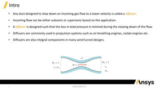
• Any ductdesigned to slow down an incoming gas flow to a lower velocity is called a diffuser.
• Incoming flow can be either subsonic or supersonic based on the application.
• A diffuser is designed such that the loss in total pressure is minimal during the slowing down of the flow.
• Diffusers are commonly used in propulsion systems such as air breathing engines, rocket engines etc.
• Diffusers are also integral components in many wind tunnel designs.
𝐴∗
𝑀 = 1
𝑀1 > 1
𝑠1, 𝑝01
𝑀2 < 1
𝑠2
𝑝02
3.
3
Ideal vs. RealDiffuser
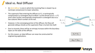
• An ideal diffuser is one in which the incoming flow is slowed by an
isentropic compression to lower velocities.
• The supersonic flow entering the diffuser at 𝑀1 is isentropically
compressed in a convergent duct to Mach 1 at the throat (𝑎𝑟𝑒𝑎 = 𝐴∗
)
and is then further isentropically compressed in a divergent duct to a
low subsonic Mach number at the exit.
• However, in the converging portion of the diffuser, the flow will
generate oblique shocks as the supersonic flow is turned into itself.
• Due to viscosity, there will be an entropy increase within the boundary
layers on the walls of the diffuser.
• For this reason, an ideal diffuser can never be constructed for
engineering applications.
𝑠2 = 𝑠1
𝑝0,2 = 𝑝0,1
𝐴∗
𝑀 = 1
𝑀1 > 1
𝑠1, 𝑝01
𝑀2 < 1
𝑠2
𝑝02
4.
4
Ideal vs. RealDiffuser (cont.)
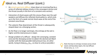
• An actual supersonic diffuser slows down an incoming flow by a
series of reflected oblique shocks in the convergent section and
the throat (usually in the form of a constant area section).
• Interaction of shock waves with the viscous flows near the wall
weakens and diffuses the reflected shock patterns, which ends
up in the form of a weak normal shock wave at the end of the
constant area throat.
• The subsonic flow downstream of the throat is subsequently
slowed down via a diverging section.
• As the flow is no longer isentropic, the entropy at the exit is
higher and the total pressure is lower.
• Design problem of a diffuser - design the converging, constant
area and the diverging section to obtain the desired exit Mach
number with the least possible total pressure loss. (In other
words, trying to keep 𝑝0,2/𝑝0,1 as close to unity as possible.)
𝑠2 > 𝑠1
𝑝0,2 < 𝑝0,1
𝐴𝑡
𝑀1 > 1
𝑠1, 𝑝01
𝑀2 < 1
𝑠2 > 𝑠1
𝑝02
< 𝑝01
𝑀 ≈ 1 Normal shock
(Weak)
Note that due to entropy increase across shock
waves and boundary layers, the real diffuser
throat area, 𝐴𝑡 > 𝐴 ∗
5.
5
Wind Tunnel Designand The Role of Diffusers
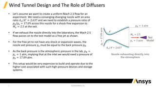
• Let's assume we want to create a uniform Mach 2.5 flow for an
experiment. We need a converging-diverging nozzle with an area
ratio 𝐴𝑒/𝐴∗
= 2.637 and we need to establish a pressure ratio of
𝑝0/𝑝𝑒 = 17.09 across this nozzle for a shock-free expansion to
𝑀𝑒 = 2.5 at the exit.
• If we exhaust the nozzle directly into the laboratory, the Mach 2.5
flow passes on to the test model as a free jet as shown.
• For the free jet to not have any shock or expansion waves, the
nozzle exit pressure 𝑝𝑒 must be equal to the back pressure 𝑝𝐵.
• As the back pressure is the atmospheric pressure in the lab, 𝑝𝐵 =
𝑝𝑒 = 1 atm, implying that at the inlet we would need a pressure of
𝑝0 = 17.09 atm.
• This setup would be very expensive to build and operate due to the
higher cost associated with such high-pressure devices and storage
systems.
𝑀𝑒 = 2.5
𝑝𝑒 = 1 𝑎𝑡𝑚
Test
Model
𝑝𝐵 = 1 𝑎𝑡𝑚
𝐴∗
𝐴𝑒/𝐴∗
= 2.637
𝑝
0
=
17.09
𝑎𝑡𝑚
Nozzle exhausting directly into
the atmosphere
6.
6
Normal Shock Diffuser
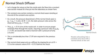
•Let's change the setup so that the nozzle exits the flow into a constant
area section instead of a free jet into the laboratory as shown here.
• The constant area section contains a normal shock wave standing at
the end of the constant-area section.
• As a result, the pressure downstream of the normal shock wave is
𝑝2 = 𝑝𝐵 = 1 𝑎𝑡𝑚. At 𝑀 = 2.5, the static pressure ratio across the
shock will be 𝑝2/𝑝𝑒 = 7.125.
• Thus, 𝑝𝑒 = 0.14 𝑎𝑡𝑚 at the nozzle exit. In order to ensure proper
isentropic flow through the nozzle, requiring a pressure ratio of 𝑝0/𝑝𝑒
= 17.09, we would now need a reservoir with a pressure of only
2.4 𝑎𝑡𝑚!
• This is considerably less than 17.09 atm required in the previous
design.
• The normal shock wave acts as a diffuser by slowing the air at 𝑀 =
2.5 to the subsonic value of 𝑀 = 0.513 behind the shock.
𝐴∗
𝑝
0
=
2.4
𝑎𝑡𝑚
𝑀𝑒 = 2.5
𝑝𝑒 = 0.14 𝑎𝑡𝑚
Test
Model
𝑝
2
=
𝑝
𝐵
=
1
𝑎𝑡𝑚
Normal Shock
Constant Area
Nozzle exhausting into a
constant area duct with a
normal shock at the exit
7.
7
Normal Shock Diffuser(cont.)
• The addition of the diffuser allows us to produce the required 𝑀 = 2.5 flow more efficiently.
However, this approach has some problems:
‐ A normal shock is the strongest possible shock and creates the largest pressure loss. Replacing it with
weaker shocks can help reduce the total pressure loss and the required reservoir pressure 𝑝0.
‐ Flow unsteadiness and instabilities cause the normal shock to move and fluctuate constantly. This would
give rise to uncertainty about the quality of the flow in the constant-area duct.
‐ The introduction of the test model in the test section would cause oblique waves from the model to
propagate downstream, making the flow three-dimensional and causing the normal shock to vanish.
8.
𝑝
0 𝑀𝑒 =2.5
𝑝𝑒 Test Model
Test Section
𝑀
<<
1
𝑀 ≈ 1 Normal
(weak) shock
Diffuser
Nozzle
𝐴𝑡,1
𝐴𝑡,2
1
2
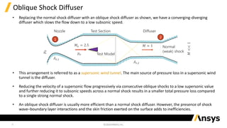
• Replacing the normal shock diffuser with an oblique shock diffuser as shown, we have a converging-diverging
diffuser which slows the flow down to a low subsonic speed.
• This arrangement is referred to as a supersonic wind tunnel. The main source of pressure loss in a supersonic wind
tunnel is the diffuser.
• Reducing the velocity of a supersonic flow progressively via consecutive oblique shocks to a low supersonic value
and further reducing it to subsonic speeds across a normal shock results in a smaller total pressure loss compared
to a single strong normal shock.
• An oblique shock diffuser is usually more efficient than a normal shock diffuser. However, the presence of shock
wave–boundary layer interactions and the skin friction exerted on the surface adds to inefficiencies.
8
Oblique Shock Diffuser
9.
9
Two Throats ofa Supersonic Wind Tunnel
• As seen from the schematic, the supersonic wind tunnel has two throats:
‐ Nozzle throat with area 𝐴𝑡,1 called the first throat
‐ Diffuser throat with area 𝐴𝑡,2 called the second throat
• For steady flow through the wind tunnel:
• Since the thermodynamic state of the gas is irreversibly changed when going through shock waves, the properties at
the two locations will differ and thus the two throats must have different areas.
• Assuming sonic flow at both stations 1 and 2, we can get the following relation using the isentropic equations:
• As the total pressure always decreases across shock waves, 𝑝0,2 < 𝑝0,1, the second throat must always be larger than
the first throat, 𝐴𝑡,2∗ > 𝐴𝑡,1.
𝐴𝑡,2∗
𝐴𝑡,1
=
𝑝0,1
𝑝0,2
ሶ
𝑚 = 𝜌1
∗
𝑉1
∗
𝐴𝑡,1 = 𝜌2𝑉2𝐴𝑡,2
10.
10
Efficiency of Diffusers
•The efficiency of a diffuser can be evaluated based on several figures of
merit.
• The most commonly used definition (related to wind tunnel work) is based
on the comparison of the actual total pressure ratio across the diffuser
𝑝𝑑0
/𝑝0, with the total pressure ratio across a hypothetical normal shock
wave at the test section Mach number 𝑝02
/𝑝01
:
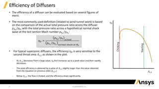
• For typical supersonic diffusers, the efficiency 𝜂𝐷 is very sensitive to the
second throat area 𝐴𝑡,2 as shown in the plot.
‐ As 𝐴𝑡,2 decreases from a large value, 𝜂𝐷first increases up to a peak value and then rapidly
decreases.
‐ The peak efficiency is obtained by a value of 𝐴𝑡,2 slightly larger than the value obtained
from the equation on previous slide (𝐴𝑡,2∗).
‐ Below 𝐴𝑡,2∗ the flow is choked, and the efficiency drops significantly.
𝜂𝐷 =
Τ
𝑝𝑑0
𝑝0 𝑎𝑐𝑡𝑢𝑎𝑙
Τ
𝑝02
𝑝01 𝑛𝑜𝑟𝑚𝑎𝑙 𝑠ℎ𝑜𝑐𝑘 𝑎𝑡 𝑀𝑒
𝐴𝑡,2
𝜂𝐷
Choking
Starting
11.
11
The Starting Problem
•When the flow through a wind tunnel is first started, a complicated transient flow pattern is established, which,
after some time, settles to a steady flow as we have discussed in this lesson.
• In most cases, the starting process is usually accompanied by a normal shock wave traversing the entire duct –
from the nozzle entrance to the diffuser exit.
• When this starting shock wave is at the inlet to the diffuser, the second throat area must be large enough to
allow the passage of the mass flow behind a normal shock. This value is given by 𝐴𝑡,2∗ corresponding to the total
pressure ratio across a normal shock at the test section Mach number, 𝑝0,2/𝑝0,1.
‐ This starting value of throat area is always larger than that corresponding to the peak efficiency.
‐ If 𝐴𝑡,2 is less than this starting value, the normal shock will remain upstream of the diffuser, and the wind tunnel will not start properly.
‐ If 𝐴𝑡,2 is equal to or more than this value then the normal shock will proceed through the diffuser section and the wind tunnel will start
properly.
• This is the reason why many advanced wind tunnels use variable-geometry diffusers.
12.
12
Summary
• In thislesson we analyzed flows through diffusers and wind tunnels where diffusers play a vital role.
• We looked at the differences between an idealized and a real diffuser.
• We also looked at the two throats of a supersonic wind tunnel and how they give rise to the starting
problem and the means with which it can be addressed.