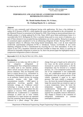
Int. J. Mech. Eng. Res. & Tech 2019
ISSN 2454 – 535X www.ijmert.com
Vol. 11, Issue. 3, Sep 2019
PERFORMANCE AND ANALYSIS OF A CONDENSER WITH DIFFERENT
REFRIGERANTS USING CFD
Mr. Menda Santhan Kumar, Mr. P.Chinna ,
Dr. Chollangi Rajesh, Mr A. Anil Kumar
Abstract
R-22 is a very commonly used refrigerant having wide applications. We have a big challenge to
replace R-22 because of HCFCs, which deplete the ozone layer and harmful to the environment. As
per Montreal Protocol we promised to be banned by 2020. Since being an unconventional &non eco-
friendly product it is being replaced by R-134a. Nano Al2O3 gives better performance hence it is
succeeded after R-22. Refrigerant R-134a is currently being used in every sector of industries, as a
part of Nano element it was accepted having multipurpose use in less quantity. Being less in quantity
& economical aspect considered it to be an influencing refrigerant till date. Having Al2O3 a metal
component reduces its efficiency from being heated immediately, thus a new & more improved
world-wide experimented refrigerant R-744 is introduced. Various eco-friendly & non ozone
depleting refrigerant R-744 is manufactured by recycling the Co2 from atmosphere. It does not
consist of any CFCs, hazardous chemicals and also available at cheap rate. Hence it is proving an
efficient & sustainable refrigerant at current era. So, threw the present paper the highlighted study on
compression refrigeration system is discussed.
Keywords: R-22, R-134a, R-744, Co2, CFCs, Al2O3
Introduction
Condensers in use today may fall in either of
two categories: refrigerated or
nonrefrigerated. Non- refrigerated condensers
are widely used as raw material, product,
and/or solvent recovery devices in chemical
process industries. They are frequently used
prior to control devices (e.g., incinerators or
absorbers). Refrigerated condensers are used
as air pollution control devices for treating
emission streams with high VOC
concentrations (usually > 5,000 ppmv) in
applications involving gasoline bulk
terminals, storage, etc. Condenser control
technology is unique in that it not only
reduces emissions to the atmosphere but also
captures or recovers VOCs, potentially for
additional use. Condensation is a separation
technique in which one or more volatile
components of a vapor mixture are separated
from the remaining vapors through saturation
followed by a phase change. The phase
change from gas to liquid can be achieved in
two ways: (a) the system pressure can be
increased at a given temperature, or (b) the
temperature may be lowered at a constant
pressure. In a two-component system where
one of the components is non condensable
(e.g., air), condensation occurs at dew point
(saturation) when the partial pressure of the
volatile compound is equal to its vapor
pressure. The more volatile a compound is
(e.g., the lower the normal boiling point), the
larger the amount that can remain as vapor at
a given temperature; hence the lower the
temperature required for saturation
(condensation). Refrigeration is often
employed to obtain the low temperatures
required for acceptable removal efficiencies.
This chapter is limited to the evaluation of
refrigerated condensation at constant
(atmospheric) pressure.
Department of Mechanical Engineering, Pragati Engineering College,Surampalem ,India
The removal efficiency of a
condenser is dependent on the emission
stream characteristics including the nature of
the VOC in question (vapor
pressure/temperature relationship), VOC
concentration, and the type of coolant used.
Any component of any vapor mixture can be
condensed
if brought to a low enough temperature and
allowed to come to equilibrium. The vapor
pressure dependence on temperature for
selected compounds (Erikson, 1980). A
condenser cannot lower the inlet
concentration to levels below the saturation
concentration at the coolant temperature.
Removal efficiencies of approximately 50 to
90 percent can be achieved with coolants
such as chilled water and brine solutions, and
removal efficiencies above 90 percent can be
achieved with ammonia, liquid nitrogen,
chlorofluorocarbons,
hydrochlorofluorocarbons, or
hydrofluorocarbons, depending on the VOC
composition and concentration level of the
emission stream.
Objectives of the study
 The main objective is to replace R22
refrigerant which ones released reacts
with the ozone layer,causing significant
damage.
 And to analyze and identify better,
efficient & sustainable replacement of
R22 refrigerant among R134A and R
744.
Review of Literature
Dalkilic AS and Wongwises S[1] The study shows
that HCR134a hydrocarbon refrigerant could be an
alternative refrigerant for replacement the existing
R134a refrigerant. Harby K[2] Results of the study
showed that in spite of highly flammable
characteristics, hydrocarbons can offer proper
alternatives to the halogenated refrigerants from the
standpoint of environment impact, energy
efficiency, COP, refrigerant mass, and compressor
temperatures. Pearson SF [3] concluded that R-
134a have better performance than the R-22 also R-
134a have zero ozone depletion potential and less
global warming potential compare to R-22. The
Metal particle of Al2O3 present in R-134a makes
the Refrigerant efficient because of heated
immediately. Another side R-744 which is made by
recycling of CO2 from atmosphere does not have
any CFCs and also not hazardous to atmosphere
also is very efficient refrigerant. R-744 has zero
ODP, lowest GWP, non-toxic, and higher
refrigerant performance than other refrigerants
.Saleh B [4]The paper conclude that the
BACKONE equations of state give generally a good
accuracy for all thermodynamic data of refrigerants
with the advantage of needing only few
experimental data for the determination of its
substance specific parameter.Yoon SH et al. [5] the
paper that the heat transfer coefficients and pressure
drop during the evaporation process of carbon
dioxide in a horizontal tube have been investigated
and At a low mass quality region during
evaporation, heat transfer coefficient increases as
mass quality increases because convective boiling
becomes more dominant. But when mass quality is
greater than a certain value, heat transfer coefficient
tends to decrease.
It is because surface tension. Neksa P [6] The
paper concluded that CO2 is one of the
natural substances and it is an
environmentally benign, safe and economical
refrigerant used for heating and cooling
systems. Existing CO2 HPWHs both in
industrial and residential sectors have been
reviewed in this study, i.e. low-temperature
and high-temperature HPWHs (which are
classified by the heat delivery temperature
below and above 80 °C). The majority of
the existing systems are still not able to
deliver the water temperature above 100 °C
due to the temperature gliding matching
between water and sCO2, the limitations in
compressors, and the constraints in heat
exchangers. Hesse U [7] Taking in
consideration the current climate scenario
many researchers has done to develop a
refrigeration system that is both energy
efficient and has less impact on environment.
This environmental impact is directly and
indirectly related to the use of HCFC and
HFC refrigerants in refrigeration systems.
The amount of depletion of Ozone layer is
link to the use of HCF seeds and HFC
refrigerant whose consequence is measured
why the ODP index that is ozone depletion
potential. And also shows the potential
alternatives of the chlorofluorocarbons.
Suneel K Kalla [8] The Paper shows that the
performance of four refrigerants as possible
alternatives to R-22 was studied with the help
of cycled software. The values of COP were
nearer to those of R-22, e.g. at 25, 45 and 55
°C condensing temperature, COP of R432a is
lower than that of R22 by about 5.5%, 4%
and 4.38% respectively. By resorting to
hydrocarbon refrigerant as a substitute to R-
22 we can reduce global warming and avoid
ozone layer damage due to use of other
refrigerants. However, the drawback of
hydrocarbon refrigerants is their flammability
due to which safety measures during their use
is essential.
Research Methodology COMPUTATIONAL
FLUID DYNAMICS
:
Computational Fluid Dynamics (CFD) is a
branch of engineering and physics that
involves the use of computer algorithms and
numerical methods to simulate and analyse
the behaviour of fluids (liquids and gases)
and their interaction with physical objects.
CFD can be used to model and predict fluid
flow, heat transfer, chemical reactions, and
other related phenomena in a wide range of
applications such as aerodynamics,
hydrodynamics, weather forecasting,
combustion, and biomedical engineering.
CFD simulations involve breaking
down a complex fluid flow problem into
smaller, simpler components that can be
analysed using mathematical equations and
computational methods. These equations
describe the behaviour of the fluid under
various conditions, such as pressure,
temperature, velocity, and viscosity. CFD
software uses numerical methods to solve
these equations and generatea detailed visual
representation of the fluid flow behaviour,
such as velocity vectors, pressuredistribution,
and temperature gradients.
CFD simulations can help engineers
and scientists to optimize the design of fluid-
based systems, such as pumps, turbines, heat
exchangers, and air foils. By using CFD
simulations to study the fluid dynamics of a
system, engineers can identify potential
design improvements, reduce energy
consumption, and optimize performance.
CFD is also widely used in research and
development to gain a better understanding of
complex fluid flow phenomena and develop
new technologies.
Computational Fluid Dynamics
(CFD) is a numerical analysis process used to
simulate and analyse the behaviour of fluids
and gases in motion. It involves the use of
computational methods, algorithms, and
computer software to solve and analyse
complex fluid flow problems.
The CFD process typically involves the
following steps:
1. Problem Definition: In this step, the
problem is defined by specifying the
physical boundaries and initial
conditions of the fluid flow problem to
be solved. This includes defining the
geometryof the domain, the type of fluid,
and the boundary conditions.
2. Grid Generation: In this step, a mesh or
grid is generated over the geometry of
the domain. The grid is used to discretize
the fluid domain into a set of small cells
or elements. The quality of the grid has a
significant impact on the accuracy and
efficiency of the CFD simulation.
3. Mathematical Modelling In this step, the
governing equations of fluid dynamics,
such as the Navier-Stokes equations, are
discretized using numerical methods to
obtain a set of algebraic equations that
can be solved on a computer. The
mathematical model also includes any
additional physics, such as turbulence or
heat transfer, that need to be considered
in the simulation.
4. Solution Algorithm: In this step, a
numerical solution algorithm is chosen to
solve the discretized equations. This
can include various numerical
techniques such as finite volume,finite
element, or spectral methods.
5. Simulation Execution: In this step, the
CFD simulation is executed using the
solution algorithm and the grid generated
in the previous steps. The simulation
results are then computed and stored for
post-processing.
6. Post-Processing: In this step, the
simulation results are analysed and
visualized. This can include generating
graphs and charts, creating animations of
the fluid flow, and extracting
information about key parameters such
as pressure, velocity, and temperature.
7. Validation and Verification: In this step,
the CFD results are compared with
experimental or analytical data to
validate and verify the accuracy of the
simulation. This helps to ensure that the
CFD results are reliable and can be used
for engineering design and analysis.
The CFD process is iterative, and
several iterations may be required to
converge to a solution that is both
accurate and stable. The CFD process is
used in various fields, including
aerospace, automotive, energy, and
biomedical engineering.
Space claim:
Space Claim is a solid modeling CAD
(computer-aided design) software that runs
on Microsoft Windows and developed by
Space Claim Corporation. The company is
headquartered in Concord,
Massachusetts. Space Claim Corporation was
founded in 2005 to develop 3D solid
modeling software for mechanical
engineering. Its first CAD application was
launched in 2007 and used an approach to
solid modeling where design concepts are
created by pulling, moving, filling,
combining, and reusing 3D shapes. It was
acquired by Ansys in May 2014, Inc, and was
integrated in subsequent versions of Ansys
Simulation packages as a built-in 3D
modeler. Space Claim Corporation Markets
Space Claim Engineer directly to end-user
and indirectly by other channels. Space
Claim also licenses its software for OEMs,
such as ANSYS Flow International
Corporation Catal CAD, and Ignite
Technology which markets a version of
Space Claim for jewelry design. The below
figure shows the geometric modal of the
condenser as shown in Figure 1.
Fig:
1
Geo
met
ry
Pre-processor
Pre-processing consists of the input of a flow
problem to a CFD program by means of an
operator- friendly interface and the
subsequent transformation of this input into a
form suitable for use by the solver. The user
activities at the pre-processing stage involve:
• Definition of the geometry of the region of
interest: the computational domain
• Grid generation – the sub-division of
the domain into a number of smaller,
non-overlappingsubdomains: a grid (or mesh)
of cells (or control volumes or elements)
• Selection of the physical and chemical
phenomena that need to be modelled.
The solution to a flow problem (velocity,
pressure, temperature etc.) is defined at nodes
inside each cell. The accuracy of a CFD
solution is governed by the number of cells in
the grid. In general, the larger the number of
cells, the better the solution accuracy. Both
the accuracy of a solution and its cost in
terms of necessary computer hardware and
calculation time are dependent on the
fineness of the grid. Optimal meshes are
often non-uniform: finer in areas where large
variations occur from point to point and
coarser in regions with relatively little
change. Efforts are under way to develop
CFD codes with a (self-) adaptive meshing
capability. Ultimately such programs will
automatically refine the grid in areas of rapid
variations. At present it is still up to the skills
of the CFD user to design a grid that is a
suitable compromise between desired
accuracy and solution cost. The below
figures [2-12] represents the Meshing of the Model and parameters considered.
Fig:2 Mesh of the modal
Boundary conditions:
Fig:3 Boundary conditions of the model
RESULTS AND DISCUSSIONS:
R134a
A substantial amount of basic development work still needs to be done before these techniques are
robust enough to be incorporated into commercial CFD codes and simulation is shown in Figures [4-
12]
Fig:4 Temperature contour (R13a)
Fig:5 Pressure contour (R13a) Fig:6 Eddy Viscosity(R13a)
Fig:7 Temperature contour (R22a) Fig:8Pressure contour (R22a)
Fig:9Eddy Viscosity(R22a) Fig:10 Temperature contour (R744)
450
400
350
300
250
200
150
100
50
0
R134A
R744
R22
TEMPERATURE
Fig:11 Pressure contour (R744) Fig:12 Eddy Viscosity(R744)
RESULTS: The Graph 1 shows the comparison of the temperatures of the three refrigerants, among
those R744 liberates less temperature to the environment than other refrigerants.
Graph: 1 Comparing temperature variations
CONCLUSION:
It is concluded that by observing the
temperature and pressure variations among
these three refrigerants R-134a have better
performance than the R-22 also R-134a have
zero ozone depletion potential and less global
warming potential compare to R-22. The
Metal particle of Al2O3 present in R-134a
makes the refrigerant inefficient because of
heated immediately. On other side R-744
which is made by recycling of CO2 from
atmosphere does not have any CFCs and also
not hazardous to atmosphere also is very
efficient refrigerant. R-744 has zero ODP,
lowest GWP, non-toxic, and higher
refrigerant performance than other
refrigerants.
REFERENCES:
1. Dalkilic AS and Wongwises S 2010 Int.
Commun. Heat Mass Transf.37 1340
2. Harby K 2017 Renew. Sustain. Energy
Rev. 73 1247.
3. Pearson SF.Natural refrigerants for heat
pumps. IEA Heat Pump Center
Newsletter 2004; 20:13–16.
4. Saleh B, Wendland M. Screening of
pure fluids as alternative refrigerants.
International Journal of Refrigeration
2006; 29: 260–269.
5. YoonSH, ChoES, HwangYW, KimMS,
MinK, KimY. Characteristics of
evaporative heat transfer and pressure
drop of carbon dioxide and correlation
development. International Journal of
Refrigeration 2004; 27 pages 111–119.
6. Neksa P.CO2 heat pump systems.
International Journal of Refrigeration
2002; 25:421 pages– 427.
7. Hesse U, Kruse H. Alternatives for
CFC’s and HCFC 22 based on CO 2.
IIF-IIR Commission B1/B2: Ghent,
Belgium, 1993 pages 317–325.
8. Suneel K Kalla, B B Arora
,Performance analysis of R22 and its
substitutes in air conditioners, Journal
of Thermal Engineering, Vol. 4, No. 1,
pp. 1724-1736, January, 2018

peer reviewed journals.pdf

  • 2.
    Int. J. Mech.Eng. Res. & Tech 2019 ISSN 2454 – 535X www.ijmert.com Vol. 11, Issue. 3, Sep 2019 PERFORMANCE AND ANALYSIS OF A CONDENSER WITH DIFFERENT REFRIGERANTS USING CFD Mr. Menda Santhan Kumar, Mr. P.Chinna , Dr. Chollangi Rajesh, Mr A. Anil Kumar Abstract R-22 is a very commonly used refrigerant having wide applications. We have a big challenge to replace R-22 because of HCFCs, which deplete the ozone layer and harmful to the environment. As per Montreal Protocol we promised to be banned by 2020. Since being an unconventional &non eco- friendly product it is being replaced by R-134a. Nano Al2O3 gives better performance hence it is succeeded after R-22. Refrigerant R-134a is currently being used in every sector of industries, as a part of Nano element it was accepted having multipurpose use in less quantity. Being less in quantity & economical aspect considered it to be an influencing refrigerant till date. Having Al2O3 a metal component reduces its efficiency from being heated immediately, thus a new & more improved world-wide experimented refrigerant R-744 is introduced. Various eco-friendly & non ozone depleting refrigerant R-744 is manufactured by recycling the Co2 from atmosphere. It does not consist of any CFCs, hazardous chemicals and also available at cheap rate. Hence it is proving an efficient & sustainable refrigerant at current era. So, threw the present paper the highlighted study on compression refrigeration system is discussed. Keywords: R-22, R-134a, R-744, Co2, CFCs, Al2O3 Introduction Condensers in use today may fall in either of two categories: refrigerated or nonrefrigerated. Non- refrigerated condensers are widely used as raw material, product, and/or solvent recovery devices in chemical process industries. They are frequently used prior to control devices (e.g., incinerators or absorbers). Refrigerated condensers are used as air pollution control devices for treating emission streams with high VOC concentrations (usually > 5,000 ppmv) in applications involving gasoline bulk terminals, storage, etc. Condenser control technology is unique in that it not only reduces emissions to the atmosphere but also captures or recovers VOCs, potentially for additional use. Condensation is a separation technique in which one or more volatile components of a vapor mixture are separated from the remaining vapors through saturation followed by a phase change. The phase change from gas to liquid can be achieved in two ways: (a) the system pressure can be increased at a given temperature, or (b) the temperature may be lowered at a constant pressure. In a two-component system where one of the components is non condensable (e.g., air), condensation occurs at dew point (saturation) when the partial pressure of the volatile compound is equal to its vapor pressure. The more volatile a compound is (e.g., the lower the normal boiling point), the larger the amount that can remain as vapor at a given temperature; hence the lower the temperature required for saturation (condensation). Refrigeration is often employed to obtain the low temperatures required for acceptable removal efficiencies. This chapter is limited to the evaluation of refrigerated condensation at constant (atmospheric) pressure. Department of Mechanical Engineering, Pragati Engineering College,Surampalem ,India
  • 3.
    The removal efficiencyof a condenser is dependent on the emission stream characteristics including the nature of the VOC in question (vapor pressure/temperature relationship), VOC concentration, and the type of coolant used. Any component of any vapor mixture can be condensed if brought to a low enough temperature and allowed to come to equilibrium. The vapor pressure dependence on temperature for selected compounds (Erikson, 1980). A condenser cannot lower the inlet concentration to levels below the saturation concentration at the coolant temperature. Removal efficiencies of approximately 50 to 90 percent can be achieved with coolants such as chilled water and brine solutions, and removal efficiencies above 90 percent can be achieved with ammonia, liquid nitrogen, chlorofluorocarbons, hydrochlorofluorocarbons, or hydrofluorocarbons, depending on the VOC composition and concentration level of the emission stream. Objectives of the study  The main objective is to replace R22 refrigerant which ones released reacts with the ozone layer,causing significant damage.  And to analyze and identify better, efficient & sustainable replacement of R22 refrigerant among R134A and R 744. Review of Literature Dalkilic AS and Wongwises S[1] The study shows that HCR134a hydrocarbon refrigerant could be an alternative refrigerant for replacement the existing R134a refrigerant. Harby K[2] Results of the study showed that in spite of highly flammable characteristics, hydrocarbons can offer proper alternatives to the halogenated refrigerants from the standpoint of environment impact, energy efficiency, COP, refrigerant mass, and compressor temperatures. Pearson SF [3] concluded that R- 134a have better performance than the R-22 also R- 134a have zero ozone depletion potential and less global warming potential compare to R-22. The Metal particle of Al2O3 present in R-134a makes the Refrigerant efficient because of heated immediately. Another side R-744 which is made by recycling of CO2 from atmosphere does not have any CFCs and also not hazardous to atmosphere also is very efficient refrigerant. R-744 has zero ODP, lowest GWP, non-toxic, and higher refrigerant performance than other refrigerants .Saleh B [4]The paper conclude that the BACKONE equations of state give generally a good accuracy for all thermodynamic data of refrigerants with the advantage of needing only few experimental data for the determination of its substance specific parameter.Yoon SH et al. [5] the paper that the heat transfer coefficients and pressure drop during the evaporation process of carbon dioxide in a horizontal tube have been investigated and At a low mass quality region during evaporation, heat transfer coefficient increases as mass quality increases because convective boiling becomes more dominant. But when mass quality is greater than a certain value, heat transfer coefficient tends to decrease.
  • 4.
    It is becausesurface tension. Neksa P [6] The paper concluded that CO2 is one of the natural substances and it is an environmentally benign, safe and economical refrigerant used for heating and cooling systems. Existing CO2 HPWHs both in industrial and residential sectors have been reviewed in this study, i.e. low-temperature and high-temperature HPWHs (which are classified by the heat delivery temperature below and above 80 °C). The majority of the existing systems are still not able to deliver the water temperature above 100 °C due to the temperature gliding matching between water and sCO2, the limitations in compressors, and the constraints in heat exchangers. Hesse U [7] Taking in consideration the current climate scenario many researchers has done to develop a refrigeration system that is both energy efficient and has less impact on environment. This environmental impact is directly and indirectly related to the use of HCFC and HFC refrigerants in refrigeration systems. The amount of depletion of Ozone layer is link to the use of HCF seeds and HFC refrigerant whose consequence is measured why the ODP index that is ozone depletion potential. And also shows the potential alternatives of the chlorofluorocarbons. Suneel K Kalla [8] The Paper shows that the performance of four refrigerants as possible alternatives to R-22 was studied with the help of cycled software. The values of COP were nearer to those of R-22, e.g. at 25, 45 and 55 °C condensing temperature, COP of R432a is lower than that of R22 by about 5.5%, 4% and 4.38% respectively. By resorting to hydrocarbon refrigerant as a substitute to R- 22 we can reduce global warming and avoid ozone layer damage due to use of other refrigerants. However, the drawback of hydrocarbon refrigerants is their flammability due to which safety measures during their use is essential.
  • 5.
    Research Methodology COMPUTATIONAL FLUIDDYNAMICS : Computational Fluid Dynamics (CFD) is a branch of engineering and physics that involves the use of computer algorithms and numerical methods to simulate and analyse the behaviour of fluids (liquids and gases) and their interaction with physical objects. CFD can be used to model and predict fluid flow, heat transfer, chemical reactions, and other related phenomena in a wide range of applications such as aerodynamics, hydrodynamics, weather forecasting, combustion, and biomedical engineering. CFD simulations involve breaking down a complex fluid flow problem into smaller, simpler components that can be analysed using mathematical equations and computational methods. These equations describe the behaviour of the fluid under various conditions, such as pressure, temperature, velocity, and viscosity. CFD software uses numerical methods to solve these equations and generatea detailed visual representation of the fluid flow behaviour, such as velocity vectors, pressuredistribution, and temperature gradients. CFD simulations can help engineers and scientists to optimize the design of fluid- based systems, such as pumps, turbines, heat exchangers, and air foils. By using CFD simulations to study the fluid dynamics of a system, engineers can identify potential design improvements, reduce energy consumption, and optimize performance. CFD is also widely used in research and development to gain a better understanding of complex fluid flow phenomena and develop new technologies. Computational Fluid Dynamics (CFD) is a numerical analysis process used to simulate and analyse the behaviour of fluids and gases in motion. It involves the use of computational methods, algorithms, and computer software to solve and analyse complex fluid flow problems. The CFD process typically involves the following steps: 1. Problem Definition: In this step, the problem is defined by specifying the physical boundaries and initial conditions of the fluid flow problem to be solved. This includes defining the geometryof the domain, the type of fluid, and the boundary conditions. 2. Grid Generation: In this step, a mesh or grid is generated over the geometry of the domain. The grid is used to discretize the fluid domain into a set of small cells or elements. The quality of the grid has a significant impact on the accuracy and efficiency of the CFD simulation. 3. Mathematical Modelling In this step, the governing equations of fluid dynamics, such as the Navier-Stokes equations, are discretized using numerical methods to obtain a set of algebraic equations that can be solved on a computer. The mathematical model also includes any additional physics, such as turbulence or heat transfer, that need to be considered in the simulation. 4. Solution Algorithm: In this step, a numerical solution algorithm is chosen to solve the discretized equations. This can include various numerical techniques such as finite volume,finite element, or spectral methods. 5. Simulation Execution: In this step, the CFD simulation is executed using the solution algorithm and the grid generated in the previous steps. The simulation results are then computed and stored for post-processing. 6. Post-Processing: In this step, the simulation results are analysed and visualized. This can include generating graphs and charts, creating animations of the fluid flow, and extracting information about key parameters such as pressure, velocity, and temperature. 7. Validation and Verification: In this step, the CFD results are compared with experimental or analytical data to validate and verify the accuracy of the simulation. This helps to ensure that the CFD results are reliable and can be used for engineering design and analysis. The CFD process is iterative, and several iterations may be required to converge to a solution that is both accurate and stable. The CFD process is used in various fields, including aerospace, automotive, energy, and
  • 6.
    biomedical engineering. Space claim: SpaceClaim is a solid modeling CAD (computer-aided design) software that runs on Microsoft Windows and developed by Space Claim Corporation. The company is headquartered in Concord,
  • 7.
    Massachusetts. Space ClaimCorporation was founded in 2005 to develop 3D solid modeling software for mechanical engineering. Its first CAD application was launched in 2007 and used an approach to solid modeling where design concepts are created by pulling, moving, filling, combining, and reusing 3D shapes. It was acquired by Ansys in May 2014, Inc, and was integrated in subsequent versions of Ansys Simulation packages as a built-in 3D modeler. Space Claim Corporation Markets Space Claim Engineer directly to end-user and indirectly by other channels. Space Claim also licenses its software for OEMs, such as ANSYS Flow International Corporation Catal CAD, and Ignite Technology which markets a version of Space Claim for jewelry design. The below figure shows the geometric modal of the condenser as shown in Figure 1. Fig: 1 Geo met ry Pre-processor Pre-processing consists of the input of a flow problem to a CFD program by means of an operator- friendly interface and the subsequent transformation of this input into a form suitable for use by the solver. The user activities at the pre-processing stage involve: • Definition of the geometry of the region of interest: the computational domain • Grid generation – the sub-division of the domain into a number of smaller, non-overlappingsubdomains: a grid (or mesh) of cells (or control volumes or elements) • Selection of the physical and chemical phenomena that need to be modelled. The solution to a flow problem (velocity, pressure, temperature etc.) is defined at nodes inside each cell. The accuracy of a CFD solution is governed by the number of cells in the grid. In general, the larger the number of cells, the better the solution accuracy. Both the accuracy of a solution and its cost in terms of necessary computer hardware and calculation time are dependent on the fineness of the grid. Optimal meshes are often non-uniform: finer in areas where large variations occur from point to point and coarser in regions with relatively little change. Efforts are under way to develop CFD codes with a (self-) adaptive meshing capability. Ultimately such programs will automatically refine the grid in areas of rapid variations. At present it is still up to the skills of the CFD user to design a grid that is a suitable compromise between desired accuracy and solution cost. The below
  • 8.
    figures [2-12] representsthe Meshing of the Model and parameters considered. Fig:2 Mesh of the modal Boundary conditions: Fig:3 Boundary conditions of the model RESULTS AND DISCUSSIONS: R134a A substantial amount of basic development work still needs to be done before these techniques are robust enough to be incorporated into commercial CFD codes and simulation is shown in Figures [4- 12] Fig:4 Temperature contour (R13a)
  • 9.
    Fig:5 Pressure contour(R13a) Fig:6 Eddy Viscosity(R13a) Fig:7 Temperature contour (R22a) Fig:8Pressure contour (R22a) Fig:9Eddy Viscosity(R22a) Fig:10 Temperature contour (R744)
  • 10.
    450 400 350 300 250 200 150 100 50 0 R134A R744 R22 TEMPERATURE Fig:11 Pressure contour(R744) Fig:12 Eddy Viscosity(R744) RESULTS: The Graph 1 shows the comparison of the temperatures of the three refrigerants, among those R744 liberates less temperature to the environment than other refrigerants. Graph: 1 Comparing temperature variations CONCLUSION: It is concluded that by observing the temperature and pressure variations among these three refrigerants R-134a have better performance than the R-22 also R-134a have zero ozone depletion potential and less global warming potential compare to R-22. The Metal particle of Al2O3 present in R-134a makes the refrigerant inefficient because of heated immediately. On other side R-744 which is made by recycling of CO2 from atmosphere does not have any CFCs and also not hazardous to atmosphere also is very efficient refrigerant. R-744 has zero ODP, lowest GWP, non-toxic, and higher refrigerant performance than other refrigerants. REFERENCES: 1. Dalkilic AS and Wongwises S 2010 Int. Commun. Heat Mass Transf.37 1340 2. Harby K 2017 Renew. Sustain. Energy Rev. 73 1247. 3. Pearson SF.Natural refrigerants for heat pumps. IEA Heat Pump Center Newsletter 2004; 20:13–16. 4. Saleh B, Wendland M. Screening of pure fluids as alternative refrigerants. International Journal of Refrigeration 2006; 29: 260–269. 5. YoonSH, ChoES, HwangYW, KimMS, MinK, KimY. Characteristics of evaporative heat transfer and pressure drop of carbon dioxide and correlation development. International Journal of Refrigeration 2004; 27 pages 111–119. 6. Neksa P.CO2 heat pump systems. International Journal of Refrigeration 2002; 25:421 pages– 427. 7. Hesse U, Kruse H. Alternatives for CFC’s and HCFC 22 based on CO 2. IIF-IIR Commission B1/B2: Ghent, Belgium, 1993 pages 317–325. 8. Suneel K Kalla, B B Arora ,Performance analysis of R22 and its substitutes in air conditioners, Journal of Thermal Engineering, Vol. 4, No. 1, pp. 1724-1736, January, 2018