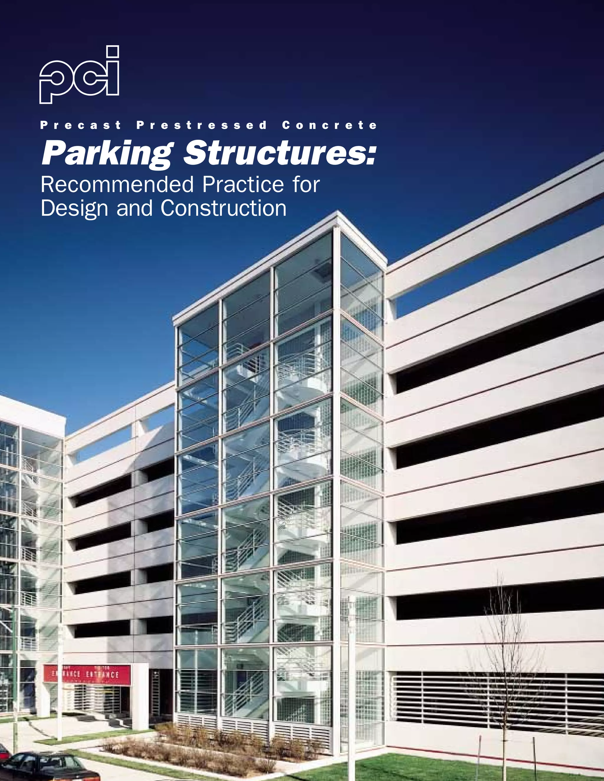
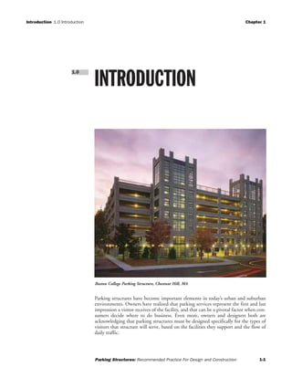
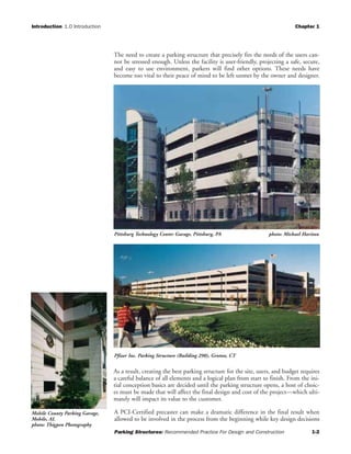
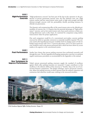
This document provides recommended practices for the design and construction of precast prestressed concrete parking structures. It discusses factors that influence the durability and functionality of parking structures, such as concrete quality, drainage, and security design. The document emphasizes the importance of designing structures to withstand environmental deterioration over their service life, while also considering their operational needs and costs. It provides guidance on elements like access design, parking configurations, lighting, and signage to optimize a structure's performance.

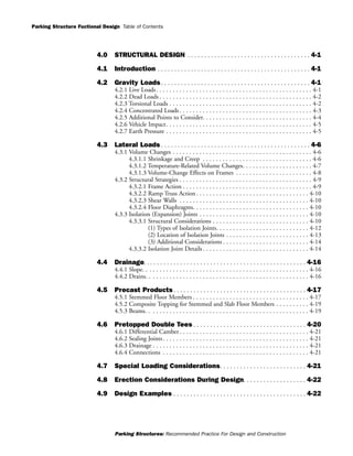
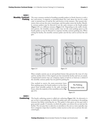
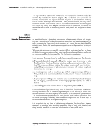
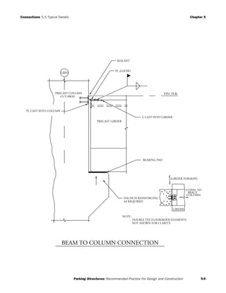
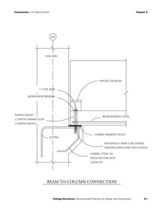
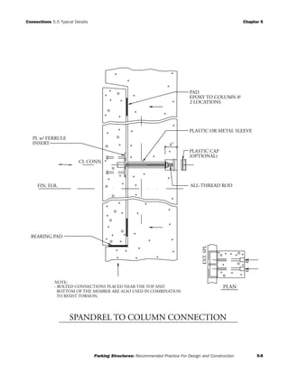
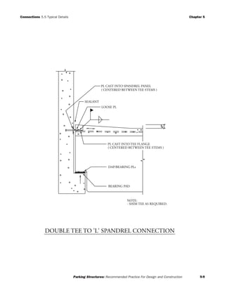
![Connections 5.5 Typical Details Chapter 5
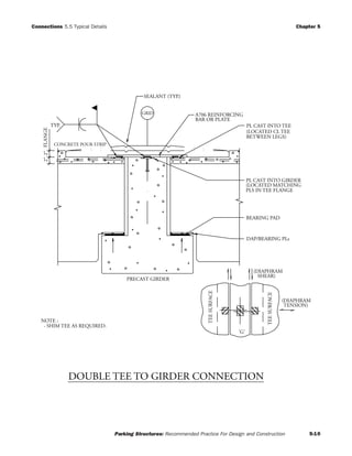
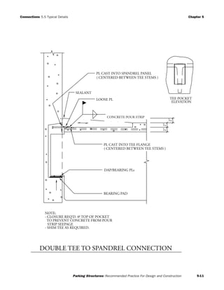
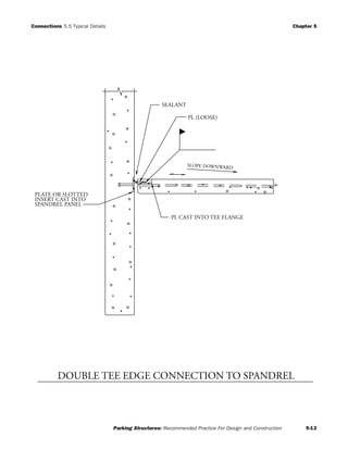
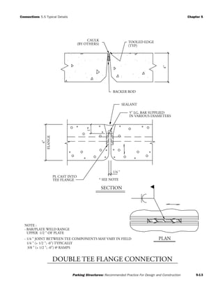
Parking Structures: Recommended Practice For Design and Construction 5-5
PRECAST
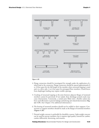
COLUMN
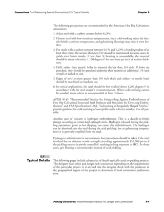
GRID
PLAN
PIER TO BE ADEQUATELY DESIGNED
FOR ERECTION & SERVICE LOADS.
[RECOMMENDED MIN. REINF'G.: 4)#9
BARSw/ HOOKED ENDS & TIES TO
PROVIDE CONFINEMENT AROUND
ANCHOR BOLTS].
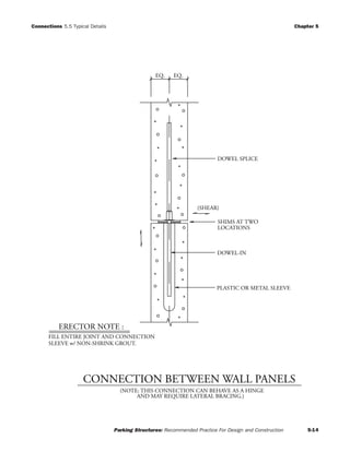
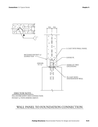
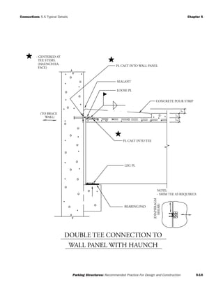
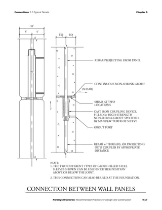
ERECTOR NOTE :
BASE PL REINFORCING
EMBEDMENTS
POCKETS
(GROUTED AFTER ERECTION)
(BOLTS TO BE SET
w/ TEMPLATE)
T.O. PIER/
FND/FTR
HEX NUTS
TOP & BOTT.
PL WSHR
(TOP & BOTT.)
BASE PL ASSEMBLY
STEEL SHIM STACK
ANCHOR BOLTS
SHIM STACK TO BE SIZED
FOR ERECTION REQUIREMENTS
FILL ENTIRE JOINT AND CONNECTION
POCKETS w/ NON-SHRINK GROUT.
COLUMN BASE CONNECTION](https://image.slidesharecdn.com/pciparkingstructuresrecommendedpractices-150305161455-conversion-gate01/85/PCI-parking-structures-recommended-practices-85-320.jpg)