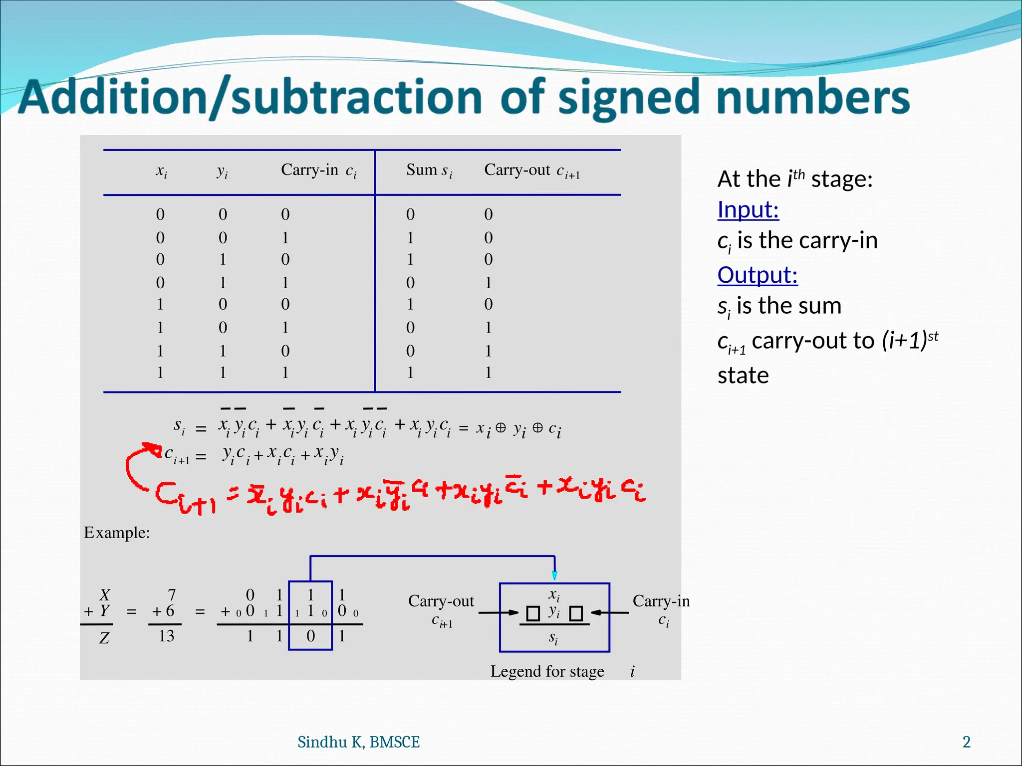
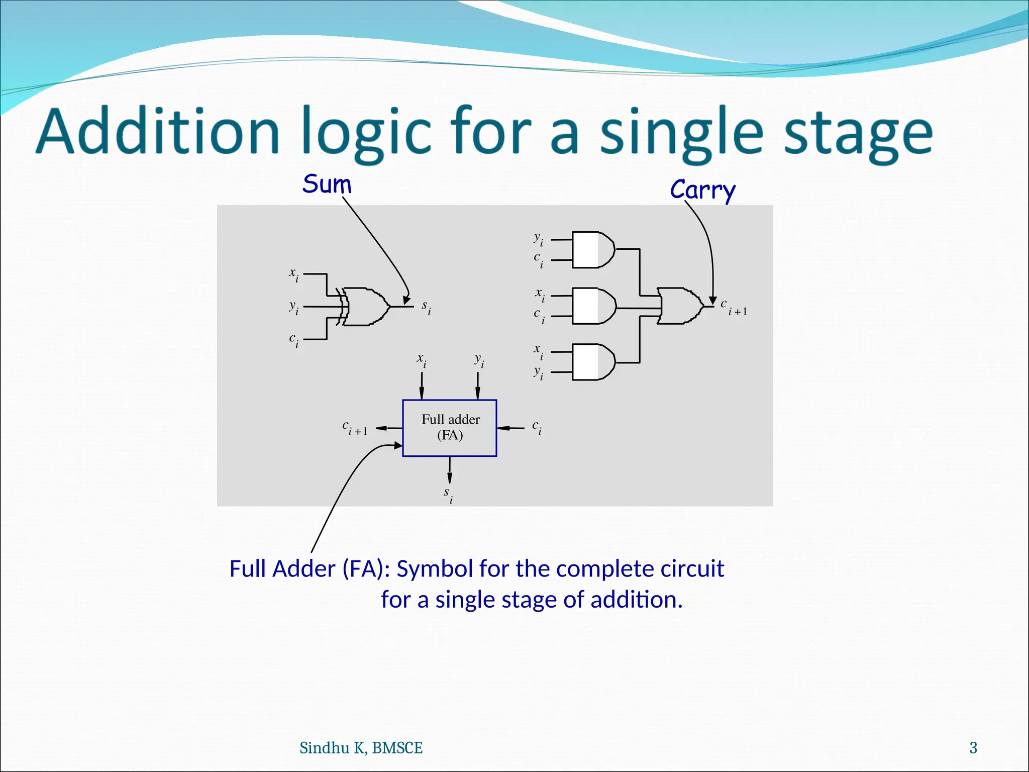
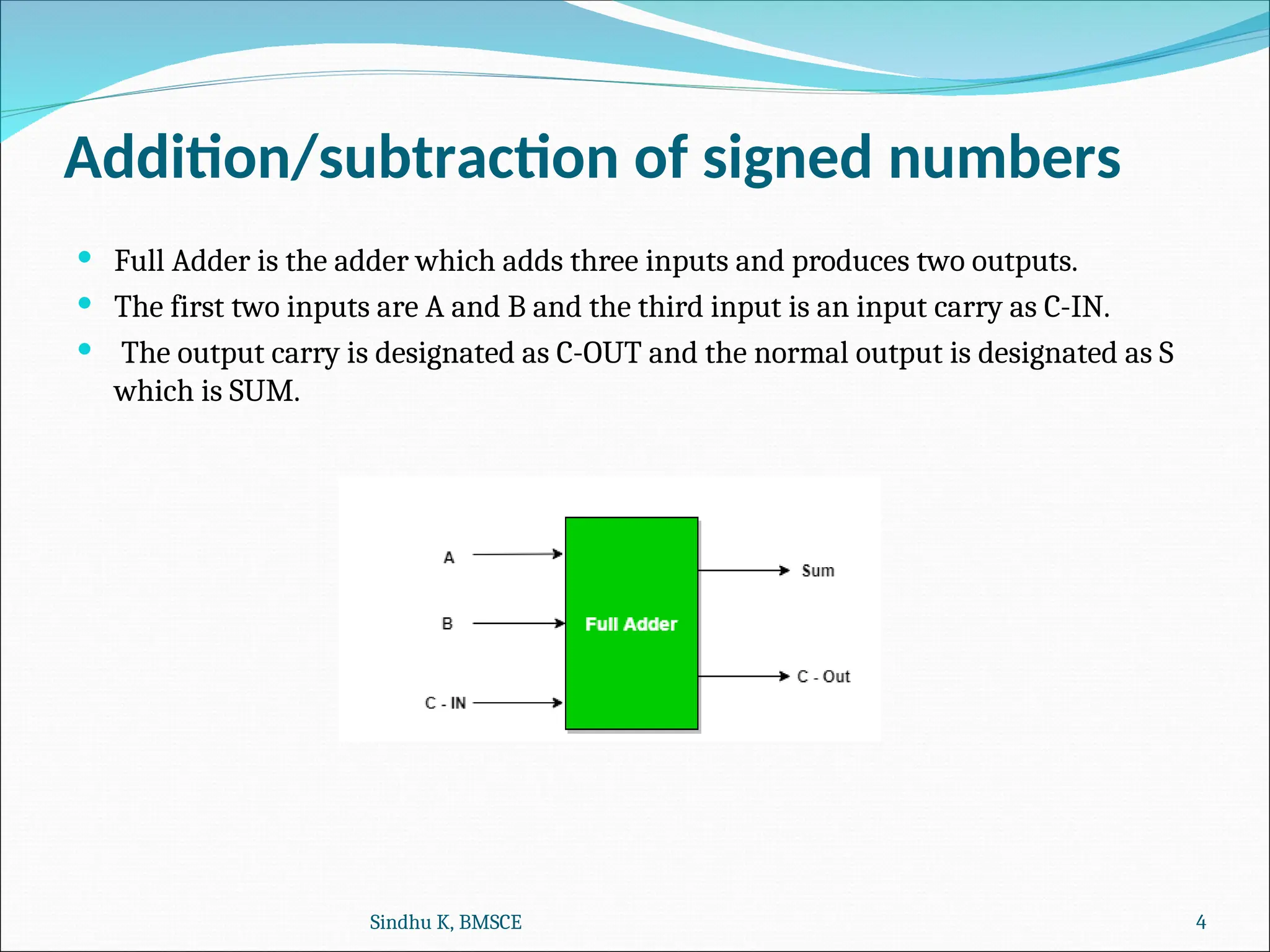
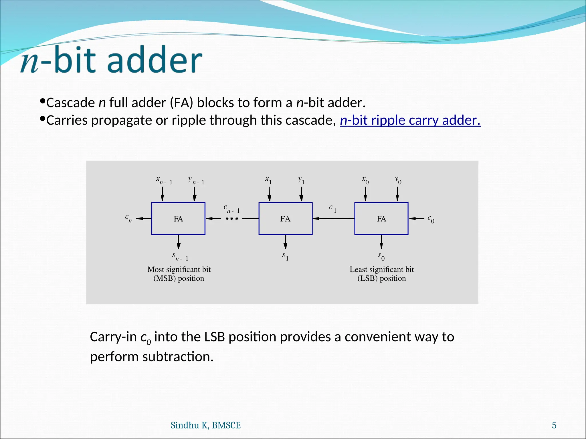
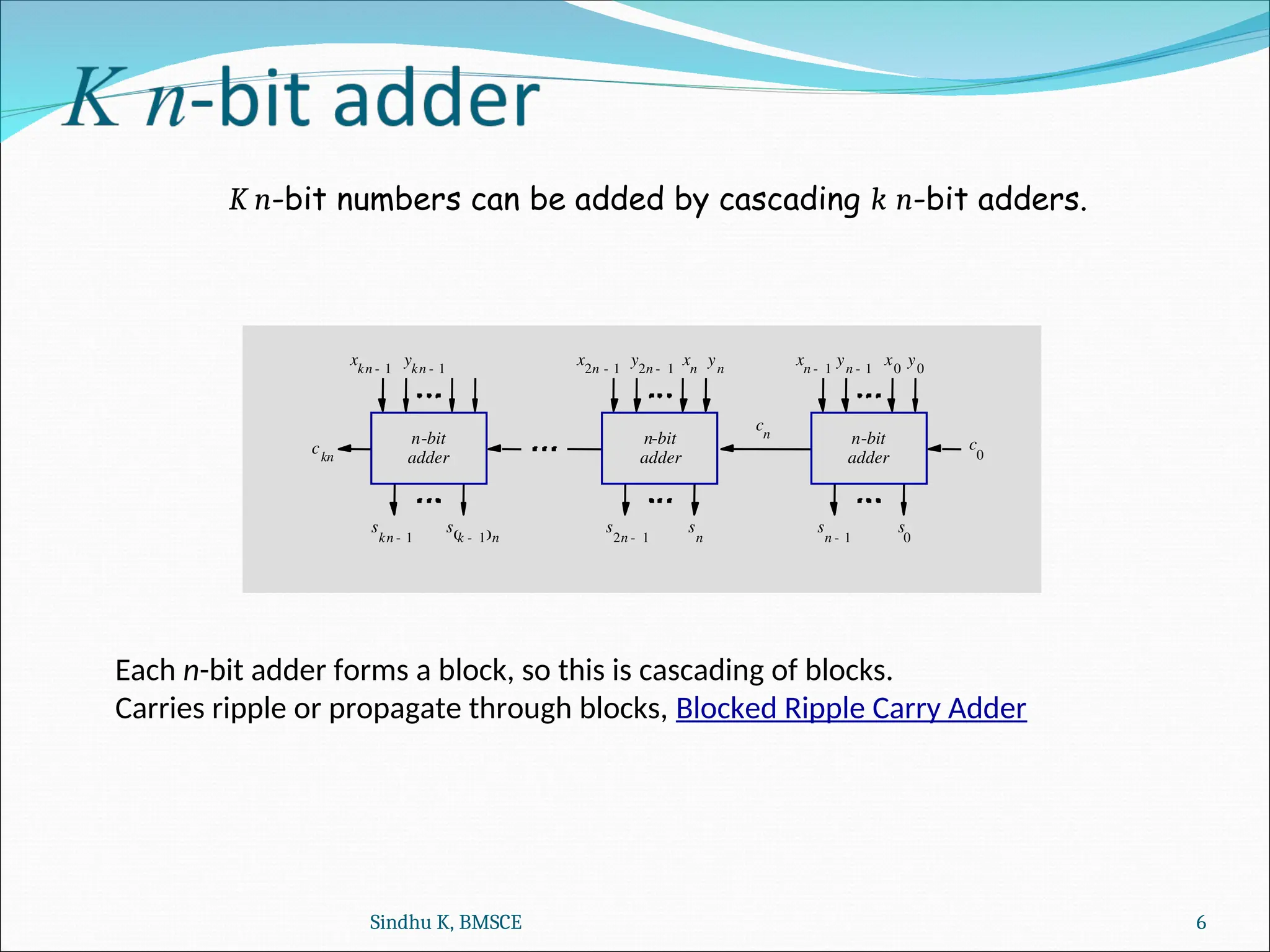
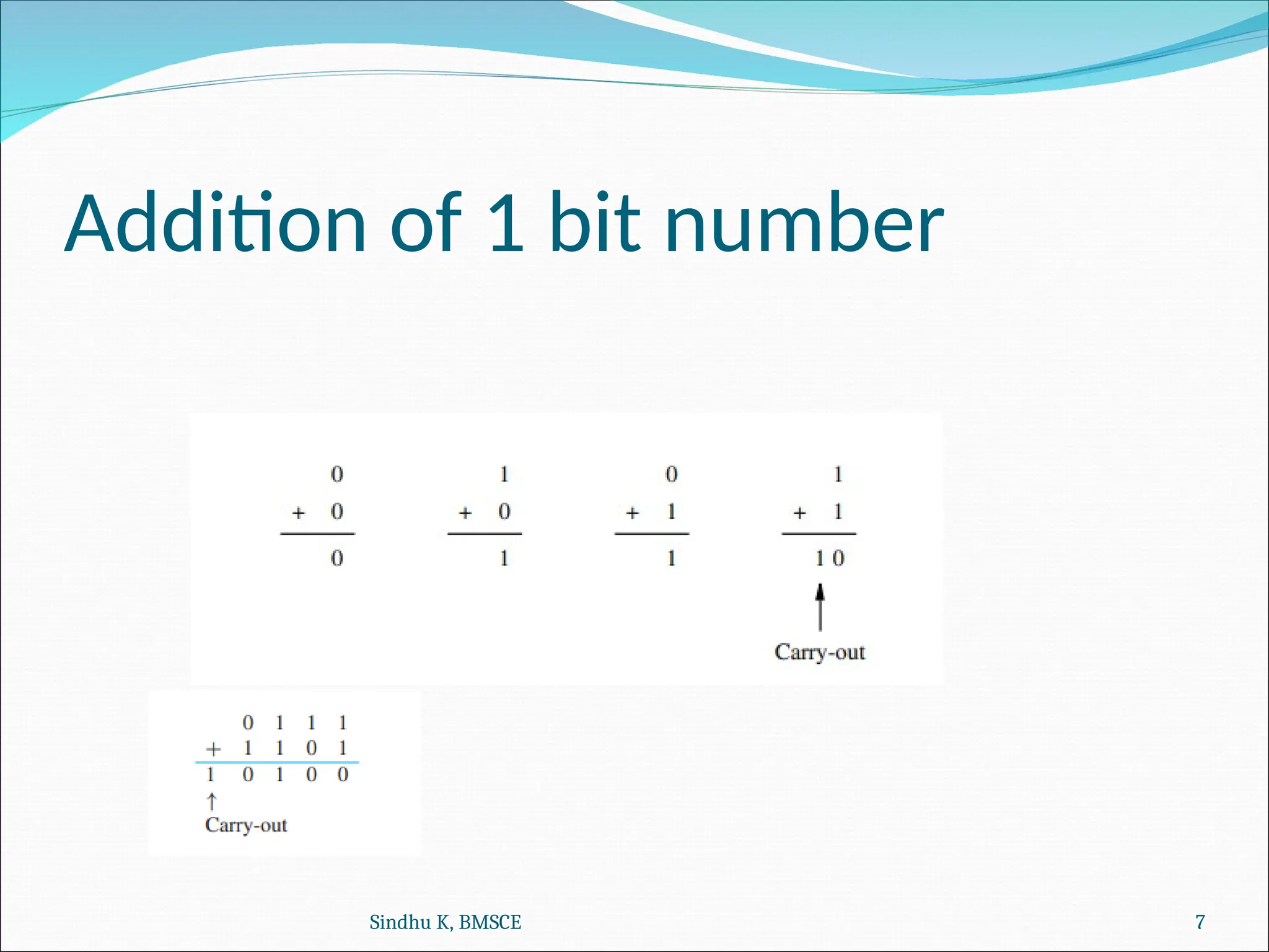
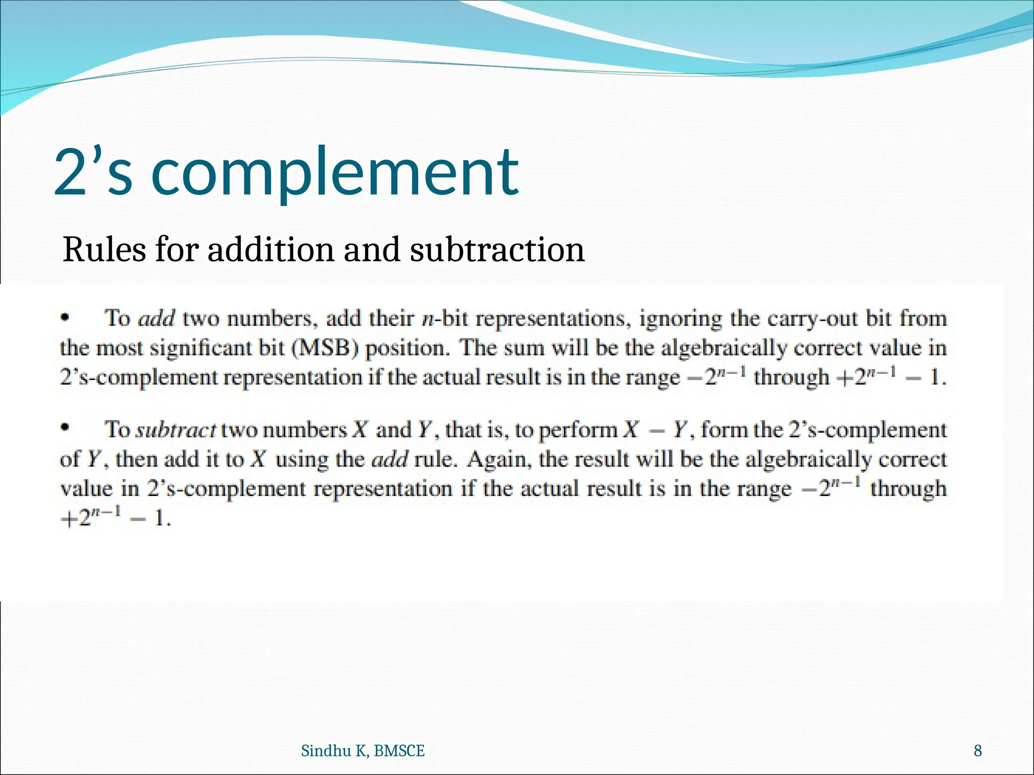
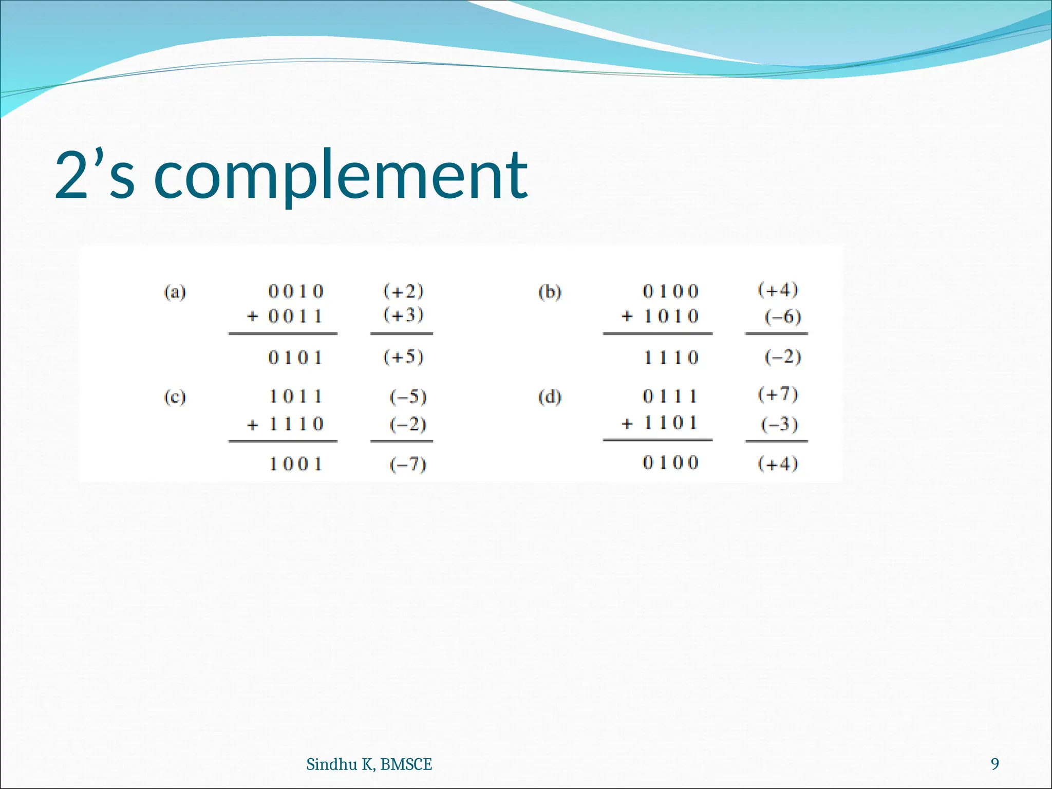
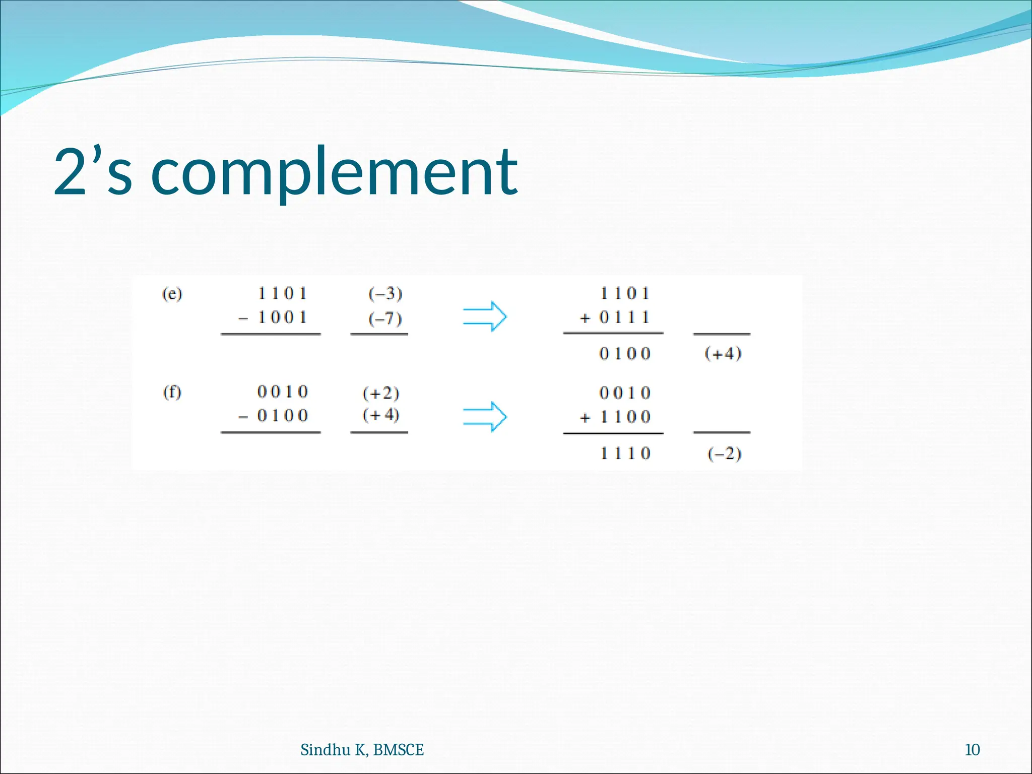
Computer Organization
and Architecture
and Architecture
Sindhu K, BMSCE 1
Reference Book :
Carl Hamacher, Computer Organization, 5th Edition, McGraw Hill Publishers
si =
ci+1 =
13
7
+ Y
1
0
0
0
1
0
1
1
0
0
1
1
0
1
1
0
0
1
1
0
1
0
0
1
0
0
0
0
1
1
1
1
0
0
0
0
1
1
1
1
Example:
1
0
= = 0
0
1 1
1
1 1 0 0
1
1 1 1
0
Legend for stage i
xi yi Carry-in ci Sum si Carry-out ci+1
X
Z
+ 6 0
+
xi
yi
si
Carry-out
ci+1
Carry-in
ci
xi
yi
ci
xi
yi
ci
xi
yi
ci
xi
yi
ci xi yi ci
 
=
+ + +
yi
ci
xi
ci
xi
yi
+ +
At the ith
stage:
Input:
ci is the carry-in
Output:
si is the sum
ci+1 carry-out to (i+1)st
state
Sindhu K, BMSCE 2
Full adder
(FA)
ci
ci 1
+
s
i
Sum Carry
yi
xi
c
i
yi
xi
c
i
yi
x
i
xi
ci
yi
si
c
i 1
+
Full Adder (FA): Symbol for the complete circuit
for a single stage of addition.
Sindhu K, BMSCE 3
Addition/subtraction of signed numbers
 Full Adder is the adder which adds three inputs and produces two outputs.
 The first two inputs are A and B and the third input is an input carry as C-IN.
 The output carry is designated as C-OUT and the normal output is designated as S
which is SUM.
Sindhu K, BMSCE 4
•Cascade n full adder (FA) blocks to form a n-bit adder.
•Carries propagate or ripple through this cascade, n-bit ripple carry adder.
FA c0
y1
x1
s1
FA
c1
y0
x0
s0
FA
cn 1
-
yn 1
-
xn 1
-
cn
sn 1
-
Most significant bit
(MSB) position
Least significant bit
(LSB) position
Carry-in c0 into the LSB position provides a convenient way to
perform subtraction.
Sindhu K, BMSCE 5
K n-bit numbers can be added by cascading k n-bit adders.
n-bit c
0
yn
xn
s
n
cn
y0
xn 1
-
s
0
ckn
s
k 1
-
 n
x0
yn 1
-
y2n 1
-
x2n 1
-
ykn 1
-
s
n 1
-
s
2n 1
-
s
kn 1
-
xkn 1
-
adder
n-bit
adder
n-bit
adder
Each n-bit adder forms a block, so this is cascading of blocks.
Carries ripple or propagate through blocks, Blocked Ripple Carry Adder
Sindhu K, BMSCE 6
Addition of 1 bit number
Sindhu K, BMSCE 7
2’s complement
Rules for addition and subtraction
Sindhu K, BMSCE 8
2’s complement
Sindhu K, BMSCE 9
2’s complement
Sindhu K, BMSCE 10
2’s complement
 When the actual result of an arithmetic operation is
outside representable range an arithmetic overflow
occurs.
 N bits can represent values in the range of
-2n-1
to +2n-1
-1 .
 Ex. 4 bits can represent numbers in range of -8 to +7.
Sindhu K, BMSCE 11
Detecting overflows
1) When the result of the operation is outside the representable
range an overflow occurs.
2) Overflows can only occur when the sign of the two operands
is the same and if the sign of the result is different from the sign
of the operands.
Recall that the MSB represents the sign.
 xn-1, yn-1, sn-1 represent the sign of operand x, operand y and result s
respectively.
Circuit to detect overflow can be implemented by the
following logic expression:
Sindhu K, BMSCE 12
Detecting overflows
3) It can also be shown that overflow occurs when the carry bits
cn and cn−1 are different. Therefore, a simpler circuit for
detecting overflow can be obtained by implementing the
expression cn cn−1 with an XOR gate.
⊕
Sindhu K, BMSCE 13
Detecting overflows
Example indicating overflow is occurred
1)+5 + +6
0101 + 0110 = 1011 overflow is occurred
2)+3 – (-7)
0011 – 1001 = 0011 + 0111 = 1010 overflow is occured
Sindhu K, BMSCE 14
Addition/Subtraction Logic Unit
 In order to perform the subtraction operation X − Y on 2’s-complement
numbers X and Y , we form the 2’s-complement of Y and add it to X .
 The logic circuit shown in Figure below can be used to perform either
addition or subtraction based on the value applied to the Add/Sub input
control line.
 Add/Sub input control line is set to 0 for addition, applying Y
unchanged to one of the adder inputs along with a carry-in signal c0 = 0.
 Add/Sub control line is set to 1, the Y number is 1’s-complemented (that
is, bit-complemented) by the XOR gates and c0 is set to 1 to complete the
2’s-complementation of Y .
 An XOR gate can be added to Figure to detect the overflow condition
cn cn−1.
⊕
Sindhu K, BMSCE 15
Add/Sub
control
n-bit adder
x
n 1
-
x
1
x
0
c
n
s
n 1
- s
1
s
0
c
0
y
n 1
-
y
1
y
0
•Add/sub control = 0, addition.
•Add/sub control = 1, subtraction.
Sindhu K, BMSCE 16
Addition/Subtraction Logic Unit
Addition Example
+3 + +4 = +7
0011 + 0100 = 011`
X = 0011
Y= 0100 xored with 0000 since add/sub control line is 0 and c0 bit =0
So Y= 0100
Subtraction Example
+5 – (+6) = -1
0101 – 0110 = 0101 + 1010 = 1111
X= 0101
Y = 0110 xored with 1111 since add/sub control line is 1
= 1001 + 1 since c0 bit =1 = 1010
Using add/sub control line set to 1 y is converted to 1’s complement and setting c0 bit =
1 y is converted to 2’s complement and addition is performed.
Sindhu K, BMSCE 17

Part-1_Addition_and_Subtraction_Logic_Unit.ppt

  • 1.
    Computer Organization Computer Organization andArchitecture and Architecture Sindhu K, BMSCE 1 Reference Book : Carl Hamacher, Computer Organization, 5th Edition, McGraw Hill Publishers
  • 2.
    si = ci+1 = 13 7 +Y 1 0 0 0 1 0 1 1 0 0 1 1 0 1 1 0 0 1 1 0 1 0 0 1 0 0 0 0 1 1 1 1 0 0 0 0 1 1 1 1 Example: 1 0 = = 0 0 1 1 1 1 1 0 0 1 1 1 1 0 Legend for stage i xi yi Carry-in ci Sum si Carry-out ci+1 X Z + 6 0 + xi yi si Carry-out ci+1 Carry-in ci xi yi ci xi yi ci xi yi ci xi yi ci xi yi ci   = + + + yi ci xi ci xi yi + + At the ith stage: Input: ci is the carry-in Output: si is the sum ci+1 carry-out to (i+1)st state Sindhu K, BMSCE 2
  • 3.
    Full adder (FA) ci ci 1 + s i SumCarry yi xi c i yi xi c i yi x i xi ci yi si c i 1 + Full Adder (FA): Symbol for the complete circuit for a single stage of addition. Sindhu K, BMSCE 3
  • 4.
    Addition/subtraction of signednumbers  Full Adder is the adder which adds three inputs and produces two outputs.  The first two inputs are A and B and the third input is an input carry as C-IN.  The output carry is designated as C-OUT and the normal output is designated as S which is SUM. Sindhu K, BMSCE 4
  • 5.
    •Cascade n fulladder (FA) blocks to form a n-bit adder. •Carries propagate or ripple through this cascade, n-bit ripple carry adder. FA c0 y1 x1 s1 FA c1 y0 x0 s0 FA cn 1 - yn 1 - xn 1 - cn sn 1 - Most significant bit (MSB) position Least significant bit (LSB) position Carry-in c0 into the LSB position provides a convenient way to perform subtraction. Sindhu K, BMSCE 5
  • 6.
    K n-bit numberscan be added by cascading k n-bit adders. n-bit c 0 yn xn s n cn y0 xn 1 - s 0 ckn s k 1 -  n x0 yn 1 - y2n 1 - x2n 1 - ykn 1 - s n 1 - s 2n 1 - s kn 1 - xkn 1 - adder n-bit adder n-bit adder Each n-bit adder forms a block, so this is cascading of blocks. Carries ripple or propagate through blocks, Blocked Ripple Carry Adder Sindhu K, BMSCE 6
  • 7.
    Addition of 1bit number Sindhu K, BMSCE 7
  • 8.
    2’s complement Rules foraddition and subtraction Sindhu K, BMSCE 8
  • 9.
  • 10.
  • 11.
    2’s complement  Whenthe actual result of an arithmetic operation is outside representable range an arithmetic overflow occurs.  N bits can represent values in the range of -2n-1 to +2n-1 -1 .  Ex. 4 bits can represent numbers in range of -8 to +7. Sindhu K, BMSCE 11
  • 12.
    Detecting overflows 1) Whenthe result of the operation is outside the representable range an overflow occurs. 2) Overflows can only occur when the sign of the two operands is the same and if the sign of the result is different from the sign of the operands. Recall that the MSB represents the sign.  xn-1, yn-1, sn-1 represent the sign of operand x, operand y and result s respectively. Circuit to detect overflow can be implemented by the following logic expression: Sindhu K, BMSCE 12
  • 13.
    Detecting overflows 3) Itcan also be shown that overflow occurs when the carry bits cn and cn−1 are different. Therefore, a simpler circuit for detecting overflow can be obtained by implementing the expression cn cn−1 with an XOR gate. ⊕ Sindhu K, BMSCE 13
  • 14.
    Detecting overflows Example indicatingoverflow is occurred 1)+5 + +6 0101 + 0110 = 1011 overflow is occurred 2)+3 – (-7) 0011 – 1001 = 0011 + 0111 = 1010 overflow is occured Sindhu K, BMSCE 14
  • 15.
    Addition/Subtraction Logic Unit In order to perform the subtraction operation X − Y on 2’s-complement numbers X and Y , we form the 2’s-complement of Y and add it to X .  The logic circuit shown in Figure below can be used to perform either addition or subtraction based on the value applied to the Add/Sub input control line.  Add/Sub input control line is set to 0 for addition, applying Y unchanged to one of the adder inputs along with a carry-in signal c0 = 0.  Add/Sub control line is set to 1, the Y number is 1’s-complemented (that is, bit-complemented) by the XOR gates and c0 is set to 1 to complete the 2’s-complementation of Y .  An XOR gate can be added to Figure to detect the overflow condition cn cn−1. ⊕ Sindhu K, BMSCE 15
  • 16.
    Add/Sub control n-bit adder x n 1 - x 1 x 0 c n s n1 - s 1 s 0 c 0 y n 1 - y 1 y 0 •Add/sub control = 0, addition. •Add/sub control = 1, subtraction. Sindhu K, BMSCE 16
  • 17.
    Addition/Subtraction Logic Unit AdditionExample +3 + +4 = +7 0011 + 0100 = 011` X = 0011 Y= 0100 xored with 0000 since add/sub control line is 0 and c0 bit =0 So Y= 0100 Subtraction Example +5 – (+6) = -1 0101 – 0110 = 0101 + 1010 = 1111 X= 0101 Y = 0110 xored with 1111 since add/sub control line is 1 = 1001 + 1 since c0 bit =1 = 1010 Using add/sub control line set to 1 y is converted to 1’s complement and setting c0 bit = 1 y is converted to 2’s complement and addition is performed. Sindhu K, BMSCE 17