Download to read offline
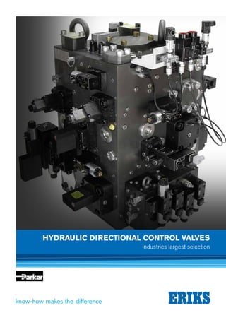

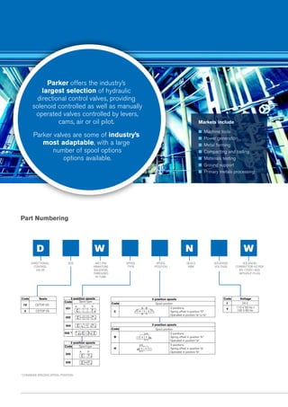
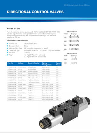


The document provides information on hydraulic directional control valves and related accessories from Parker, including: - Parker offers a large selection of solenoid-controlled and manually-operated directional control valves in various spool configurations for industries like machine tools and metal forming. - Valve part numbering codes indicate spool type, position, seals, and voltage. Series include D1VW and D3W valves in sizes NG06 and NG10. - Accessories include relief valves, pressure reducing valves, subplates, and flow control valves to integrate the valves into hydraulic circuits and manifolds.


