The document provides a schematic and component locations for the hydraulic system of a 312D2 and 313D2 excavator. It includes:
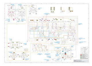
- A schematic diagram labeling hydraulic components and lines with callouts and color coding.
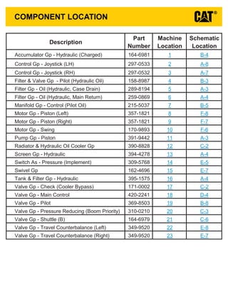
- Tables listing the components, their part numbers, locations on the machine and in the schematic.
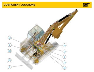
- Views showing the physical locations of components on the excavator.
- Descriptions of fluid power and electrical symbols used in the schematic.
This schematic shows the hydraulic system for a 140M or 160M motor grader. It displays the components, lines, and connections that make up the system. Lines are color coded based on their function. Component callouts provide identification numbers and locations to reference in the service manual. Taps are labeled for measuring pressure or sampling fluid at key points in the system.
This document provides a 3-page schematic for the hydraulic system of a 16M motor grader. It includes a component location table with over 40 components listed along with their part numbers and locations. The schematic itself shows the hydraulic circuit layout and color codes the different circuits. Callouts on the schematic reference components from the table by name and identification number.
This document provides an interactive schematic for a 320D and 323D excavator attachment. It includes:
- A bookmarks panel to navigate points of interest and machine views via hyperlinks.
- A button in machine views to show all callouts.
- Schematics, machine views, component tables, and other information about the attachment.
- Keyboard shortcuts and screen resolution instructions for optimal viewing.
This document contains schematics for the hydraulic system of a motor grader. Volume 1 shows the standard implement control valve configuration and includes components like accumulators, cylinders, pumps, tanks and valves. Volume 2 shows alternate implement control valve configurations and additional components like blade tip cylinders and plow/dozer cylinders. Color codes and line patterns are provided to identify different hydraulic circuits on the schematics.
This document provides a schematic and component location diagrams for the hydraulic system of a 320D and 320D L excavator. It includes:
- A hydraulic circuit diagram with callouts for components, hydraulic lines colored by circuit, and tap locations for testing and sampling.
- Tables listing hydraulic component descriptions, part numbers, and schematic/machine locations.
- Diagrams showing the machine locations of key hydraulic components like motors, pumps, valves and filters.
- Pages on fluid power and electrical symbols, and hydraulic circuit color descriptions.
This document provides a schematic and additional information for the hydraulic system of a 320D and 320D L excavator. The schematic uses lines, symbols and callouts to show the layout and connections between major hydraulic components. These include pumps, motors, cylinders, valves, filters and more. Accompanying text provides additional details on component locations, fluid pressures and flows, and other information to understand the system.
This document provides schematics and component information for the hydraulic system on a 988G wheel loader. It includes:
- A schematic of the implement and axle oil cooler system with labeled components, lines, and taps.
- A list of the components shown on the schematic with part numbers and machine/schematic locations.
- Fluid power and electrical symbols used in the schematic.
- A second schematic of the steering and brake system with the same details.
This document provides a schematic and component location guide for the hydraulic system of 525C, 535C, and 545C wheel skidders. It includes:
- A diagram of the hydraulic system schematic with labeled components and lines.
- A table listing machine components with their part numbers and locations in the schematic and on the machine.
- Information on tap locations for measuring pressure and sampling fluid.
- Reference pages on fluid power and electrical symbols.
PLANO HIDRAULICO INTERACTIVO 336DL Renr99800001juanManuel1001
This document provides a schematic for the hydraulic system of an excavator. It includes symbols for hydraulic components and their connections. The schematic can be navigated using blue hyperlinks and bookmarks. Component locations and identification numbers are listed in tables for reference.
This document provides schematics and location information for electrical components on a 416E backhoe loader. It includes:
- Component location charts showing the schematic location and machine location for electrical components in the cab and engine/chassis.
- Connector location charts showing the schematic location of connectors between harnesses.
- Tables with Component Identifiers (CIDs), Module Identifiers (MIDs), and Fault codes that may be used for troubleshooting.
This document provides a hydraulic schematic for a 325C excavator. It includes:
- A component table that lists each hydraulic component, its part number, machine location, and location on the schematic.
- The schematic diagram labels each hydraulic component and shows how they are connected via hydraulic lines and valves. Line styles indicate different types of hydraulic lines.
- Additional reference information includes fluid power and electrical symbols, and a diagram showing the location of major hydraulic components on the machine.
This document provides an interactive schematic for a construction machine. It includes a table of contents that allows the user to navigate between different machine views. Blue, underlined text throughout the document acts as hyperlinks to different sections. Buttons at the top allow the user to view all callouts or zoom in/out of schematic views.
This document provides a schematic and definitions for the hydraulic system of D3G, D4G, and D5G track-type tractors. It includes a key for line patterns, callouts, component locations listed with part numbers, tap locations listed by letter, and a schematic diagram of the hydraulic circuit layout and components.
The document provides information about an interactive schematic for a machine:
- The Bookmarks panel allows quick navigation between points of interest in the schematic and machine views.
- Clickable blue underlined text are hyperlinks that can be used to navigate.
- A button in the top right of machine views makes all callouts visible.
This document provides an interactive schematic for a backhoe loader. It contains over 200 labeled components across three volumes covering the cab, chassis, engine, and rear systems. Users can click on underlined blue text to navigate between schematic and machine views of components. Bookmarks allow quick navigation to points of interest in the document.
This document provides a schematic and component location guide for the electrical system of a 950H and 962H wheel loader. It includes 228 numbered components across two volumes - one for cab wiring and one for chassis wiring. The summary lists the component types and their schematic and machine locations to help technicians quickly navigate and service the electrical system.
This document provides a schematic for the hydraulic system of Caterpillar skid steer, multi-terrain, and compact track loaders. It includes a component table that lists parts, their location on the machine, and location on the schematic. It also includes a tap table that lists hydraulic pressure and sampling points. The schematic shows the hydraulic components and lines with labels, numbers, and colors to indicate circuits. Callouts provide numbers, names, and part numbers for the components.
This document provides information on hydraulic system components and symbols for Caterpillar 416E, 422E, and 428E backhoe loaders. It includes a table listing hydraulic components, diagrams of the implement and steering pump and hydraulic circuits, and pages describing the loader and backhoe valves and hydraulic symbols.
This document provides information about electrical system components for Caterpillar 525C, 535C, and 545C wheel skidder machines. It includes two tables: one listing components and their locations in schematics and on machines, and another listing electrical connectors and their schematic and machine locations. The tables provide key details about components and connectors to help with electrical system troubleshooting and repair.
This document provides a summary of the electrical system for a 120H and 135H motor grader, including:
- A schematic showing the location of electrical components and connectors.
- Tables listing electrical components with their schematic and machine locations.
- Diagnostic codes and their descriptions to help troubleshoot issues.
- Specifications for electrical components like senders, resistors, solenoids, and switches.
- Charts identifying wire colors and their associated functions in the electrical system.
This document provides locations for electrical components and connectors on a motor grader. It lists over 150 components with their schematic symbol location and corresponding machine location. It also lists 24 connectors with their schematic locations. The document is intended to help technicians locate components and connectors based on schematic diagrams.
This document provides information about the electrical system schematic and components for Caterpillar 416C, 426C, 428C, 436C, and 438C backhoe loaders. It includes:
- A chart listing electrical components and their locations on the schematic and machine views
- A chart identifying connector locations by number on the schematic and machine
- Specifications for resistors, solenoids, and switches
- A table describing wire colors and their associated functions
This document provides electrical component information for an excavator, including:
- Component and connector location charts detailing where parts are located on schematics and the machine.
- CID/MID/FMI codes for diagnosing faults in the engine/pump controller, engine controller, and tool controller modules.
- Event codes and their meanings for the engine/pump and engine controllers.
- Specifications for related manuals and an off-machine switch.
This document provides a component table that lists hydraulic system components for a MD6540C Rotary Drill. It includes 62 components with their description, part number, schematic location, and machine location. The table is intended to allow users to easily identify components and find their location on the schematic diagram or machine.
This document provides information about components and locations for hydraulic systems on Caterpillar track loaders and skid steer loaders. It includes two volumes, with the first covering standard implements and the second covering high flow implements. The document lists component descriptions and their locations on schematics and machines. It also identifies hydraulic tap locations for measuring system pressures.
DIAGRAMA ELECTRICO INTERACTIVO CAT 336DL Uenr26380001juanManuel1001
This document provides an interactive schematic for a machine. It includes:
- Symbols and definitions for electrical, hydraulic, and other components
- Instructions for setting the screen resolution for best viewing
- Bookmarks panel and hyperlinks to navigate schematic and machine views
- Buttons to zoom, fit to page, and find all callouts
This document provides a schematic for the hydraulic system of a M325D material handler. It includes a legend that identifies the line patterns used for different hydraulic circuits and callouts. A table lists component locations by number and tap locations for pressure sampling by letter. Hydraulic circuit color descriptions are also provided to identify different systems such as the idle pump output, drive pump output, and steering control circuit.
This document provides a summary of key electrical components for a track-type tractor, including their schematic symbol locations and physical machine locations. Over 50 components are listed, such as the alternator, batteries, sensors, solenoids, lamps, and controls. The components are organized in a table with their schematic symbol and corresponding machine location.
Understanding Catalytic Converter Theft:
What is a Catalytic Converter?: Learn about the function of catalytic converters in vehicles and why they are targeted by thieves.
Why are They Stolen?: Discover the valuable metals inside catalytic converters (such as platinum, palladium, and rhodium) that make them attractive to criminals.
Steps to Prevent Catalytic Converter Theft:
Parking Strategies: Tips on where and how to park your vehicle to reduce the risk of theft, such as parking in well-lit areas or secure garages.
Protective Devices: Overview of various anti-theft devices available, including catalytic converter locks, shields, and alarms.
Etching and Marking: The benefits of etching your vehicle’s VIN on the catalytic converter or using a catalytic converter marking kit to make it traceable and less appealing to thieves.
Surveillance and Monitoring: Recommendations for using security cameras and motion-sensor lights to deter thieves.
Statistics and Insights:
Theft Rates by Borough: Analysis of data to determine which borough in NYC experiences the highest rate of catalytic converter thefts.
Recent Trends: Current trends and patterns in catalytic converter thefts to help you stay aware of emerging hotspots and tactics used by thieves.
Benefits of This Presentation:
Awareness: Increase your awareness about catalytic converter theft and its impact on vehicle owners.
Practical Tips: Gain actionable insights and tips to effectively prevent catalytic converter theft.
Local Insights: Understand the specific risks in different NYC boroughs, helping you take targeted preventive measures.
This presentation aims to equip you with the knowledge and tools needed to protect your vehicle from catalytic converter theft, ensuring you are prepared and proactive in safeguarding your property.
Expanding Access to Affordable At-Home EV Charging by Vanessa WarheitForth
Vanessa Warheit, Co-Founder of EV Charging for All, gave this presentation at the Forth Addressing The Challenges of Charging at Multi-Family Housing webinar on June 11, 2024.
Implementing ELDs or Electronic Logging Devices is slowly but surely becoming the norm in fleet management. Why? Well, integrating ELDs and associated connected vehicle solutions like fleet tracking devices lets businesses and their in-house fleet managers reap several benefits. Check out the post below to learn more.
EV Charging at MFH Properties by Whitaker JamiesonForth
Whitaker Jamieson, Senior Specialist at Forth, gave this presentation at the Forth Addressing The Challenges of Charging at Multi-Family Housing webinar on June 11, 2024.
Dahua provides a comprehensive guide on how to install their security camera systems. Learn about the different types of cameras and system components, as well as the installation process.
Charging and Fueling Infrastructure Grant: Round 2 by Brandt HertensteinForth
Brandt Hertenstein, Program Manager of the Electrification Coalition gave this presentation at the Forth and Electrification Coalition CFI Grant Program - Overview and Technical Assistance webinar on June 12, 2024.
Charging Fueling & Infrastructure (CFI) Program by Kevin MillerForth
Kevin Miller, Senior Advisor, Business Models of the Joint Office of Energy and Transportation gave this presentation at the Forth and Electrification Coalition CFI Grant Program - Overview and Technical Assistance webinar on June 12, 2024.
Charging Fueling & Infrastructure (CFI) Program Resources by Cat PleinForth
Cat Plein, Development & Communications Director of Forth, gave this presentation at the Forth and Electrification Coalition CFI Grant Program - Overview and Technical Assistance webinar on June 12, 2024.
Welcome to ASP Cranes, your trusted partner for crane solutions in Raipur, Chhattisgarh! With years of experience and a commitment to excellence, we offer a comprehensive range of crane services tailored to meet your lifting and material handling needs.
At ASP Cranes, we understand the importance of reliable and efficient crane operations in various industries, from construction and manufacturing to logistics and infrastructure development. That's why we strive to deliver top-notch solutions that enhance productivity, safety, and cost-effectiveness for our clients.
Our services include:
Crane Rental: Whether you need a crawler crane for heavy lifting or a hydraulic crane for versatile operations, we have a diverse fleet of well-maintained cranes available for rent. Our rental options are flexible and can be customized to suit your project requirements.
Crane Sales: Looking to invest in a crane for your business? We offer a wide selection of new and used cranes from leading manufacturers, ensuring you find the perfect equipment to match your needs and budget.
Crane Maintenance and Repair: To ensure optimal performance and safety, regular maintenance and timely repairs are essential for cranes. Our team of skilled technicians provides comprehensive maintenance and repair services to keep your equipment running smoothly and minimize downtime.
Crane Operator Training: Proper training is crucial for safe and efficient crane operation. We offer specialized training programs conducted by certified instructors to equip operators with the skills and knowledge they need to handle cranes effectively.
Custom Solutions: We understand that every project is unique, which is why we offer custom crane solutions tailored to your specific requirements. Whether you need modifications, attachments, or specialized equipment, we can design and implement solutions that meet your needs.
At ASP Cranes, customer satisfaction is our top priority. We are dedicated to delivering reliable, cost-effective, and innovative crane solutions that exceed expectations. Contact us today to learn more about our services and how we can support your project in Raipur, Chhattisgarh, and beyond. Let ASP Cranes be your trusted partner for all your crane needs!
1. INTERACTIVE SCHEMATIC
The Bookmarks panel will allow you to
quickly navigate to points of interest.
Click on any text that is BLUE and underlined.
These are hyperlinks that can be used to navi-
gate the schematic and machine views.
When only one callout is showing on a machine view this
button will make all of the callouts visible. This button is
located in the top right corner of every machine view page.
VIEW ALL CALLOUTS
Cover Page
Information
Schematic
Machine Views
Component Table
Tap Table
Fluid Power Symbols
Electrical Symbols
Front Frame
Rear Frame
Tap Views
Features
Options
Bookmarks X
EC-C3
EC-C2 E-C60
EC-C1
E-C61
To set your screen resolution do the following:
RIGHT CLICK on the DESKTOP.
Select PROPERTIES.
CLICK the SETTINGS TAB.
MOVE THE SLIDER under SCREEN RESOLUTION
until it shows 1024 X 768.
CLICK OK to apply the resolution.
This document is best viewed at a
screen resolution of 1024 X 768.
FUNCTION
Zoom In
HOTKEYS (Keyboard Shortcuts)
Zoom Out
Fit to Page
Hand Tool
“CTRL” / “+”
KEYS
“CTRL” / “-”
“CTRL” / “0” (zero)
“SPACEBAR” (hold down)
Find “CTRL” / “F”
5. FLUID POWER SYMBOLS
ONE POSITION TWO POSITION THREE POSITION
VENTED PRESSURIZED RETURN ABOVE FLUID LEVEL RETURN BELOW FLUID LEVEL
LINES CROSSING LINES JOINING
TWO-WAY THREE-WAY FOUR-WAY
SPRING CONTROL VALVES RESTRICTION LINE RESTRICTION
(FIXED)
2-SECTION PUMP
MAIN AUX.
SPRING
(ADJUSTABLE)
VARIABILITY LINE RESTRICTION
(VARIABLE)
LINE RESTRICTION
VARIABLE and PRESSURE
COMPENSATED
PRESSURE
COMPENSATION
PUMP: VARIABLE and
PRESSURE COMPENSATED
ENERGY TRIANGLES
HYDRAULIC PNEUMATIC
MEASUREMENT
PRESSURE TEMPERATURE FLOW
ROTATING SHAFTS
UNIDIRECTIONAL BIDIRECTIONAL
PUSH-PULL LEVER PEDAL
GENERAL MANUAL PUSH BUTTON SPRING
MANUAL CONTROL SYMBOLS
HYDRAULIC MOTORS
FIXED
DISPLACEMENT
VARIABLE DISPLACEMENT
NON-COMPENSATED
UNIDIRECTIONAL
BIDIRECTIONAL
HYDRAULIC PUMPS
FLUID STORAGE RESERVOIRS
CROSSING AND JOINING LINES
VALVE ENVELOPES VALVE PORTS
BASIC COMPONENT SYMBOLS
FLUID CONDITIONER
PUMP or MOTOR
FIXED
DISPLACEMENT
VARIABLE DISPLACEMENT
NON-COMPENSATED
UNIDIRECTIONAL
BIDIRECTIONAL
VALVES
PILOT CONTROL SYMBOLS
RELEASED PRESSURE
EXTERNAL RETURN INTERNAL RETURN
REMOTE SUPPLY PRESSURE
SIMPLIFIED COMPLETE INTERNAL
SUPPLY PRESSURE
ACCUMULATORS
SPRING LOADED GAS CHARGED
SOLENOID
or MANUAL
SOLENOID
and PILOT
SOLENOID and
PILOT or MANUAL
COMBINATION CONTROLS
SOLENOID SERVO THERMAL DETENT
HYDRAULIC AND PNEUMATIC CYLINDERS
DOUBLE ACTING
SINGLE ACTING
BASIC
SYMBOL
SPRING
LOADED
CHECK VALVES
TWO
POSITION
INFINITE
POSITIONING
FLOW IN ONE
DIRECTION
FLOW ALLOWED IN
EITHER DIRECTION
THREE
POSITION
CROSS
FLOW
PARALLEL
FLOW
INTERNAL PASSAGEWAYS
NORMAL POSITION
A B
P T
A B
P T
SHIFTED POSITION INFINITE POSITION
CONTROL VALVES
ATTACHMENT
MANUAL SHUTOFF
SHUTTLE PILOT
CONTROLLED
6. ELECTRICAL SYMBOLS
Hydraulic Symbols (Electrical)
325-AG135 PK-14
Circuit Identification
Number
Wire Color Wire Gauge
Harness identification code
This example indicates
wire 135 in harness "AG".
325-PK-14
Wire Gauge
Wire Color
Circuit Number
Identification
Wire Number Identification Codes
Current Standard
Previous Standard
Electrical Schematic Example Hydraulic Schematic Example
325-PK
Wire Color
Circuit Number
Identification
B A
Wire
Wire
(EXAMPLE VALVE)
Current Standard
Transducer
(Fluid)
Transducer
(Gas / Air)
G
Generator
Electrical Wire
Pressure Switch
M
Electric Motor
Pressure Switch
(Adjustable)
Temperature Switch
Pressure
Symbol
Temperature
Symbol
Level
Symbol
Flow
Symbol
Electrical Symbols (Electrical)
T
7. SCHEMATIC PART NUMBER: 389-2422 HE 03
Components are shown installed on a fully operable machine with the key and engine off.
Refer to the appropriate Service Manual for Troubleshooting, Specifications and Systems Operations.
312D2 and 313D2 Excavator Hydraulic System
UENR3860-05
LINE PATTERNS
Drain / Return Lines
Component Group
Pilot / Load Sensing Pressure
Pressure Line
Attachment
Air Line
CALLOUTS
Taps (Pressure, Sampling, Sensor - by letter)
Components (By number)
YY
52
HYDRAULIC CIRCUIT COLOR DESCRIPTIONS
PILOT PUMP OUTPUT
DRIVE PUMP OUTPUT
LEFT TRAVEL CONTROL AND LEFT TRAVEL CIRCUIT
POWER SHIFT CONTROL CIRCUIT
SUPPLY LINE
ATTACHMENT CIRCUIT
SWING CONTROL AND SWING MOTOR CIRCUIT
DRAIN / RETURN LINE
SWING BREAK CONTROL CIRCUIT
IDLE PUMP OUTPUT
TRAVEL SPEED CONTROL CIRCUIT
BUCKET CONTROL AND BUCKET CYLINDER CIRCUIT
RIGHT TRAVEL CONTROL AND RIGHT TRAVEL CIRCUIT
BOOM CONTROL AND BOOM CYLINDER CIRCUIT
STICK CONTROL AND STICK CYLINDER CIRCUIT
(1) ACCUMULATOR GP
(6) FILTER GP
(2) CONTROL GP
(3) CONTROL GP
(4) FILTER & VALVE GP
(5) FILTER GP
(7) MANIFOLD GP
(10) MOTOR GP
(8) MOTOR GP (9) MOTOR GP
(11) PUMP GP
(12) RADIATOR & HYDRAULIC
(13) SCREEN GP
(14) SWITCH AS
(15) SWIVEL GP
(16) TANK & FILTER GP
(17) VALVE GP
(18) VALVE GP
(19) VALVE GP
(20) VALVE GP
(21) VALVE GP
(22) VALVE GP (23) VALVE GP
TRAVEL
COUNTERBALANCE
(RIGHT)
TRAVEL
COUNTERBALANCE
(LEFT)
SHUTTLE (B)
PRESSURE REDUCING
(BOOM PRIORITY)
PILOT
MAIN CONTROL
CHECK (COOLER BYPASS)
HYDRAULIC
PRESSURE (IMPLEMENT)
HYDRAULIC
OIL COOLER GP
PISTON
PISTON (RIGHT)
PISTON (LEFT)
SWING
CONTROL (PILOT OIL)
OIL (HYDRAULIC,
CASE DRAIN)
PILOT (HYDRAULIC OIL)
JOYSTICK (RH)
JOYSTICK (LH)
OIL (HYDRAULIC,
MAIN RETURN)
HYDRAULIC (CHARGED)
AA
BB
DD
CC
SOS
PG
PA1
(OUT)
bR5
(R)
bR4 PSW PTA
(DOWN)
(UP)
BL3 AL3
(CLOSE)
R2
HL
HR
T
(OPEN)
(IN)
dB1
pB1
(DOWN)
dST1
PP
(L)
(IN)
dA1
R1
(FWD)
(FWD)
(BACK) (BACK)
(UP)
BOOM CYLINDER
STICK CYLINDER
BUCKET CYLINDER
Dr
M5
Pn1
PM
M3
M1
A1
S2
S1
A2
M2
M4 A3 PS
Pn2
aR5 aL6
bL6
(OUT)
bL3
aL3
aL5
bL5
PAC
DR2
DR3 DR4 DR5 DR6
DR1
P-IN
Pi1
Pi2
PSA2 PSA1
P1
P2
T-OUT2
T-OUT1
(FWD)
(BACK)
(BACK)
(FWD)
TT
TP
T1
T2
T3
T4
CP1
CP2
JR1
(UP)
JR4
(OPEN)
JR2
(CLOSE)
JR3
(DOWN)
JL3
(IN)
JL1
(OUT)
JL4
(L)
JL2
(R)
DrM
PG
IN
OUT
T
PC
dB
dA
4
7
1
3
6
5
2
TRAVEL(L) TRAVEL(R)
JLP
JLT
JRT
JRP
BOOM
BOOM
STICK
STICK
SWING
SWING
BUCKET
BUCKET
A
B
C
D
E
F
1
2
3
4
5 6
4
5 6 3 2
1
aR3 aR2
bR3 bR1
aR1
bR2
bL1
aL1
bL2
aL4
bL4
BR3 AR3
BR2
AR2 BR1 AR1
BL1
AL1 AL2 BL2
BL4 AL4
aL2
AL2 BL2
BR3
AR3
BL4 AL4
AR1
BR1 BL1
AL1
aR2
bR2
bL4
bR3
aR3
aL4
bL2
aL2
bR1
aR1 aL1
bL1
PR PL
PR
PL
STICK(R)
BOOM(2)
STICK(2)
BUCKET
ATCH
BOOM(1)
TRAVEL(R)
TRAVEL(L)
SWING
STICK(1)
M
TRAVEL
SPEED
CHANGE
SOL.
SWING
BREAK
SOL.
HYD
LOCK
SOL.
T
P1
B1 A1
P2
B2 A2
Pp3
B A
B
A
T1
Pp3
TRAVEL MOTOR (LEFT) TRAVEL MOTOR (RIGHT)
T2 T2
T1
AG BG
BG
BG AG
B A
PR
DR
SWING MOTOR
MU
AR2
BR2
199-0504
349-9520
164-6979
310-0210
369-8503
420-2241
171-0002
395-1575
162-4696
309-5768
394-4278
390-8828
391-9442
357-1821
357-1821
369-9604
215-5037
289-8194
158-8987
297-0532
297-0533
259-0869
164-6981