SlideShare a Scribd company logo
1 of 13
Download to read offline
Click here to view the
Schematic Symbols
and Definitions page
INTERACTIVE SCHEMATIC
The Bookmarks panel will allow you to
quickly navigate to points of interest.
Click on any text that is BLUE and
underlined. These are hyperlinks
that can be used to navigate the
schematic and machine views.
When only one callout is showing on a
machine view, clicking on this button will
make all of the callouts visible. This
button is located in the top right corner
of every machine view page.
VIEW ALL CALLOUTS
Cover Page
Tables
Schematic
Machine Views
Component
Connector
Chassis View
Cab View
Engine View
Features
Options
Bookmarks X
EC-C3
EC-C2 E-C60
EC-C1
E-C61
To set your screen resolution do the following:
RIGHT CLICK on the DESKTOP.
Select PROPERTIES.
CLICK the SETTINGS TAB.
MOVE THE SLIDER under SCREEN RESOLUTION
until it shows 1024 X 768.
CLICK OK to apply the resolution.
*This document is best viewed at a
screen resolution of 1024 X 768.
*Due to different monitor sizes and PDF reader preferences
there may be some variance in linked schematic locations
FUNCTION
Zoom In
HOTKEYS (Keyboard Shortcuts)
Zoom Out
Fit to Page
Hand Tool
“CTRL” / “+”
KEYS
“CTRL” / “-”
“CTRL” / “0” (zero)
“SPACEBAR” (hold down)
Find “CTRL” / “F”
Pressure
Switch
Temperature
Switch
Level
Switch
Flow
Switch Circuit Breaker
T
ELECTRICAL SYMBOLS
Spring
(Adjustable)
Variability
Fluid
Conditioner
Pump
or Motor
BASIC HYDRAULIC
COMPONENT SYMBOLS
Click here to save a copy of
this interactive schematic
to your desktop
SCHEMATIC SYMBOLS AND DEFINITIONS
HYDRAULIC SYMBOLS - ELECTRICAL
Transducer
(Fluid)
Transducer
(Gas / Air)
G
Generator Electrical
Wire
Pressure
Switch
M
Electric
Motor
Pressure Switch
(Adjustable)
Temperature
Switch
Pressure
Switch
Temperature
Switch
Level
Switch
Flow
Switch Circuit Breaker
T
ELECTRICAL SYMBOLS
Spring
Control
Valves
Restriction Line Restriction
(Fixed)
2-Section
Pump
MAIN AUX.
Spring
(Adjustable)
Variability
Line Restriction
(Variable)
Pressure
Compensation
Pump: Variable and
Pressure Compensated
Hydraulic Pneumatic
Energy Triangles
Fluid
Conditioner
Attachment
Pump
or Motor
BASIC HYDRAULIC
COMPONENT SYMBOLS
Line Restriction
Variable and Pressure
Compensated
Vented Pressurized Return Above Fluid Level Return Below Fluid Level
FLUID STORAGE RESERVOIRS
Pressure Temperature Flow
MEASUREMENT
Unidirectional Bidirectional
ROTATING SHAFTS
One Position Two Position Three Position
Two-way Three-Way Four-Way
ENVELOPES
PORTS
CONTROL
Basic
Symbol
Spring
Loaded
Normal Position
A B
P T
A B
P T
Shifted Position Infinite Position
Shuttle Pilot
Controlled
VALVES
CHECK
Solenoid
or Manual
Solenoid
and Pilot
Solenoid and
Pilot or Manual
Solenoid Servo Thermal Detent
COMBINATION CONTROLS
T
Fuse: A component in an electrical circuit that will open the circuit if too much current flows through it.
Switch (Normally Open): A switch that will close at a specified point (temp, press, etc.). The circle indicates
that the component has screw terminals and a wire can be disconnected from it.
Switch (Normally Closed): A switch that will open at a specified point (temp, press, etc.).
No circle indicates that the wire cannot be disconnected from the component.
Ground (Wired): This indicates that the component is connected to a grounded wire.
The grounded wire is fastened to the machine.
Ground (Case): This indicates that the component does not have a wire connected to ground.
It is grounded by being fastened to the machine.
Reed Switch: A switch whose contacts are controlled by a magnet. A magnet closes the contacts of
a normally open reed switch; it opens the contacts of a normally closed reed switch.
Sender: A component that is used with a temperature or pressure gauge.
The sender measures the temperature or pressure.
Its resistance changes to give an indication to the gauge of the temperature or pressure.
Relay (Magnetic Switch): A relay is an electrical component that is activated by electricity.
It has a coil that makes an electromagnet when current flows through it.
The electromagnet can open or close the switch part of the relay.
Solenoid: A solenoid is an electrical component that is activated by electricity.
It has a coil that makes an electromagnet when current flows through it.
The electromagnet can open or close a valve or move a piece of metal that can do work.
Magnetic Latch Solenoid: An electrical component that is activated by electricity and held latched by a
permanent magnet. It has two coils (latch and unlatch) that make electromagnet
when current flows through them. It also has an internal switch that places
the latch coil circuit open at the time the coil latches.
BASIC ELECTRICAL COMPONENT SYMBOLS
Push-pull Lever Pedal
General Manual Push Button Spring
Manual Shutoff
MANUAL CONTROL
External Return Internal Return
Simplified Complete
Internal
Supply Pressure
RELEASED PRESSURE
REMOTE SUPPLY PRESSURE
PILOT CONTROL
Spring Loaded Gas Charged
ACCUMULATORS
Crossing Joining
LINES
Double Acting
Single Acting
CYLINDERS
Unidirectional
Bidirectional
FIXED DISPLACEMENT
VARIABLE DISPLACEMENT
NON- COMPENSATED
PUMPS
Unidirectional
Bidirectional
Unidirectional
Bidirectional
FIXED DISPLACEMENT
VARIABLE DISPLACEMENT
NON- COMPENSATED
MOTORS
Unidirectional
Bidirectional
Two
Position
Infinite
Positioning
FLOW IN ONE
DIRECTION
FLOW ALLOWED IN
EITHER DIRECTION
Three
Position
CROSS
FLOW
PARALLEL
FLOW
INTERNAL PASSAGEWAYS
1
2
AG-C4
111-7898
L-C12
3E-5179
9X-1123
Component
Part Number
Pin or Socket Number
Part Number: for
Connector Plug
Harness Identification Letter(s): (A, B, C, AA, AB, AC, ...)
Plug
325-AG135 PK-14
Wire Color
Wire Gauge
Receptacle
1
1
2
2
Sure-Seal connector: Typical representation
of a Sure-Seal connector. The plug and receptacle
contain both pins and sockets.
Deutsch connector: Typical representation
of a Deutsch connector. The plug contains all
sockets and the receptacle contains all pins.
Fuse (5 Amps)
5A
Harness identification code:
This example indicates wire group 325,
wire 135 in harness "AG".
L-C12
3E-5179
Wire, Cable, or Harness Assembly Identification:
Includes Harness Identification Letters and Harness
Connector Serialization Codes (see sample).
Harness Connector Serialization Code: The "C" stands for
"Connector" and the number indicates which connector in the
harness (C1, C2, C3, ...)
HARNESS AND WIRE SYMBOLS
© 2016 Caterpillar, All Rights Reserved Printed in U.S.A.
DS41-UP
Hydraulic System
MD6540C Rotary Drill
August 2016
UENR6873
COMPONENT TABLE
Description
Part
Number
Schematic
Location
Machine
Location
Description
Part
Number
Schematic
Location
Machine
Location
Cylinder - Cable Tensioning (Cab Side) 450-6484 D-10 1 Manifold - Supercharge 100-2953 B-12 50
Cylinder - Cable Tensioning (D/C Side) 450-6484 B-10 2 Motor - Drill (High Speed, Low Torque) 446-7390 G-11 51
Cylinder - Carousel Lock 1 462-3093 I-13 3 Motor - Drill (Low Speed, High Torque) 471-2902 G-10 52
Cylinder - Carousel Lock 2 462-3093 H-13 4 Motor - Engine Radiator Fan 420-1970 F-14 53
Cylinder - Carousel Rotate (4 POD) 408-6270 Motor - Final Drive (LH) 454-0811 E-11 54
Cylinder - Carousel Rotate (5 POD) 427-4976 Motor - Final Drive (RH) 454-0811 C-12 55
Cylinder - Cascading Stairs 438-534 J-3 6 Motor - HOC/COC Fan 419-935 F-13 56
Cylinder - Deck Wrench 427-164 J-13 7 Motor - Water Injection Bean Pump 479-5555 F-3 57
Cylinder - Front Dust Curtain 1 101-4058 J-7 8 Motor - Water Injection Bean Pump (Above Deck Option) 442-577 B-8 58
Cylinder - Front Dust Curtain 2 101-4058 J-7 9 Motor - Winch (16 Meter Mast) 166-7868
Cylinder - Front Jack (LH) 444-9756 F-7 10 Motor - Winch (20 Meter Mast) 471-7600
Cylinder - Front Jack (RH) 444-9756 G-7 11 Orifice - Cascading Stairs 433-914 J-4 60
Cylinder - Hobo Clamp 427-220 J-8 12 Orifice - Load Sense (AUX Pump) 414-8146 D-16 61
Cylinder - Hobo Rotate 427-221 I-8 13 Pump - Auxiliary 449-3689 C-16 62
Cylinder - Hobo Swing 427-219 I-9 14 Pump - Fan 459-9222 E-16 63
Cylinder - Main Air 439-628 I-6 15 Pump - Hand (Cascading Stairs) 438-763 J-3 64
Cylinder - Mast Lock 1 437-257 I-7 16 Pump - HVAC 459-9221 H-1 65
Cylinder - Mast Lock 2 437-257 J-7 17 Pump - Main (LH) 442-7706 D-15 66
Cylinder - Mast Raise 1 459-6706 H-6 18 Pump - Main (RH) 442-7706 B-15 67
Cylinder - Mast Raise 2 459-6706 H-5 19 Tank - Central Lube 157-7413 B-8 68
Cylinder - Pipe Catcher 1 101-4058 J-15 20 Tank - Hydraulic 460-1342 A-14 69
Cylinder - Pipe Catcher 2 101-4058 J-15 21 Valve - Aux Control 459-7667 H-3 70
Cylinder - Pipe Positioner Clamp 100-4269 I-16 22 Valve - Cascading Stairs Counter-Balance 420-708 J-5 71
Cylinder - Pipe Positioner Swing 100-4268 H-16 23 Valve - Check Drill Motor Case Drain 584-94 F-10 72
Cylinder - Pipe Rack Swing 1 426-859 J-1 24 Valve - Check Water Pump Motor 403-95 E-3 73
Cylinder - Pipe Rack Swing 2 426-859 J-10 25 Valve - Diverter (LH) 493-7514 E-12 74
Cylinder - Pipe Support Clamp 100-4269 I-14 26 Valve - Diverter (RH) 493-7514 C-12 75
Cylinder - Pipe Support Swing 100-4268 J-14 27 Valve - Fan Anti-Cavitation Check (COC/HOC 1) 423-0917 G-13 76
Cylinder - Pulldown 997-716 D-11 28 Valve - Fan Anti-Cavitation Check (COC/HOC 2) 423-0917 F-12 77
Cylinder - Rear Dust Curtain 1 461-3060 J-6 29 Valve - Fan Anti-Cavitation Check (Radiator 1) 423-0917 G-15 78
Cylinder - Rear Dust Curtain 2 461-3060 J-6 30 Valve - Fan Anti-Cavitation Check (Radiator 2) 423-0917 G-15 79
Cylinder - Rear Jack (LH) 443-6895 G-8 31 Valve - Fan Control Relief 1 422-044 E-16 80
Cylinder - Rear Jack (RH) 443-6895 F-8 32 Valve - Fan Control Relief 2 422-044 D-15 81
Cylinder - Viewing Hatch 461-3060 J-5 33 Valve - Flushing 431-873 C-11 82
Filter - Main Pump 1 (LH) 481-8634 E-13 34 Valve - Load Sense Shuttle 172-8240 D-15 83
Filter - Main Pump 1 (RH) 481-8634 C-13 35 Valve - Manually-Actuated Unloading (Cascading Stairs) 148-1404 J-4 84
Filter - Main Pump 2 (LH) 481-8634 D-13 36 Valve - Mast Control 169-6233 H-15 85
Filter - Main Pump 2 (RH) 481-8634 B-13 37 Valve - Mast Raise 441-1149 E-8 86
Filter - Tram Charge (Main Pump LH) 447-9785 E-14 38 Valve - Raise Counter-Balance 421-620 G-4 87
Filter - Tram Charge (Main Pump RH) 447-9785 C-14 39 Valve - Relief (Final Drive) LH 470-4114 E-13 88
Manifold - COC/HOC 423-9308 G-13 40 Valve - Relief (Final Drive) RH 470-4114 D-14 89
Manifold - Drain (Inside Tower Support) 441-3199 C-6 41 Valve - Relief (Hobo Clamp/Rotate 1) 101-4071 J-9 90
Manifold - Drain (Lower Mast D/C Side) 432-811 C-6 42 Valve - Relief (Hobo Clamp/Rotate 2) 101-4071 I-9 91
Manifold - Drain (Side Of Hydraulic Tank) 431-754 C-2 43 Valve - Relief (Hold-Back) 432-206 D-13 92
Manifold - Dust Collector Fan Motor 432-066 F-4 44 Valve - Relief (Pipe Positioner Clamp/Swing 1) 101-4071 I-15 93
Manifold - Fan Control 164-9540 F-15 45 Valve - Relief (Pipe Positioner Clamp/Swing 2) 101-4071 I-15 94
Manifold - Fan Return 419-924 G-12 46 Valve - Relief (Pipe Support Clamp/Swing 1) 101-4071 H-16 95
Manifold - Radiator 1 423-9308 G-14 47 Valve - Relief (Pipe Support Clamp/Swing 2) 101-4071 I-16 96
Manifold - Radiator 2 423-9308 G-14 48 Valve - Thermal Bypass 445-2771 F-12 97
Manifold - Return 430-225 E-2 49 Manifold - Cable, Brake, Diverter Control 151-4269 D-10 98
Component Locations
H-8 5
F-8 59
TAP TABLE
Tap
Number
Description
Schematic
Location
AP1 Mast Raise Aux Pressure E-4
AP2 Mast Raise Drain Pressure E-4
AP3 Aux Pump LS Relief Valve Pressure F-16
CP1 Main Pump RH Port X1 B-15
CP2 Main Pump RH Port X1 B-14
CP3 Main Pump LH Port X1 D-15
CP4 Main Pump LH Port X1 D-15
CP7 Cable Tension Valve Pressure E-10
CP8 Drill / Travel Valve Pressure E-10
CP9 Brake Valve Pressure E-10
DM1 Drian Manifold Pressure (Side of Hyd. Tank) C-2
FP1 Fan Control Relief Pressure 1 E-15
FP2 Fan Control Relief Pressure 2 E-15
FP3 Fan Anti-Cavitation Check Pressure 1 (COC/HOC) F-13
FP4 Fan Anti-Cavitation Check Pressure 2 (COC/HOC) F-13
FP5 Fan Anti-Cavitation Check Pressure 1 (Radiator) F-15
FP6 Fan Anti-Cavitation Check Pressure 2 (Radiator) F-14
FP7 Oil Fan Relief Valve Pressure G-16
FP9 Engine Fan Relief Valve Pressure F-16
HP1 Main Pump RH Output Pressure 1 B-14
HP2 Main Pump RH Output Pressure 2 B-14
HP3 Main Pump LH Output Pressure 1 D-14
HP4 Main Pump LH Output Pressure 2 D-14
R1 Fan Return Manifold Pressure G-12
R2 Return Drian Manifold Pressure E-1
SC Super Charge Manifold Pressure B-12
SUC Suction Block Pressure B-16
Tap Locations
Pressure, Sampling, and Sensor
UENR6873
42
Page,
(Dimensions:
56
inches
x
35
inches)
Components are shown installed on a fully operable machine with the key and engine off, transmission shifter
in neutral and with parking brake set.
Refer to the appropriate Service Manual for Troubleshooting, Specifications and Systems Operations.
SCHEMATIC PART NUMBER: 484-0436, CHANGE: XX, VERSION: XX
THIS SCHEMATIC IS FOR THE MD6540C ROTARY DRILL HYDRAULIC SYSTEM
MEDIA NUMBER: UENR6873
Refer to the Parts Manual using a specific serial number prefix in SIS before ordering parts from this schematic.
A
B
C
D
E
F
1
2
3
4
5
6
7
8
9
10
11
12
13
14
G
H
I
J
A
B
C
D
E
F
G
H
I
J
15
16
1
2
3
4
5
6
7
8
9
10
11
12
13
14
15
16
HYDRAULIC CIRCUIT COLOR DESCRIPTIONS
AUXILIARY PUMP OUTPUT
MAIN PUMP OUTPUT
CASCADING STAIRS CONTROL CIRCUIT
VIEWING HATCH CYLINDER CONTROL CIRCUIT
HOBO CYILNDERS CONTROL CIRCUIT
DECK WRENCH CYLINDER CONTROL CIRCUIT
FAN, SUPERCHARGER, AND DUST COLLECTOR CONTROL CIRCUIT
SUPPLY LINE
MAST RAISE CONTROL CIRCUIT
JACK CYLINDERS CONTROL CIRCUIT
MAST LOCK CYLINDER CONTROL CIRCUIT
AIR CONDITIONER CONTROL CIRCUIT
PIPE SUPPORT, RACK, CATCHER, AND POSTIONER CONTROL CIRCUIT
DRAIN / RETURN LINE
MAIN AIR CYLINDER CONTROL CIRCUIT
CENTRAL LUBE TANK CONTROL CIRCUIT
DUST CURTAIN CYLINDER CONTROL CIRCUIT
WINCH CONTROL CIRCUIT
CAROUSEL LOCK CYLINDER CONTROL CIRCUIT
TRACK CONTROL CIRCUIT
LINE PATTERNS
Drain / Return Lines
Component Group
Pilot / Load Sensing Pressure
Pressure Line
CALLOUTS
Taps (Pressure, Sampling, Sensor - by letter)
YY
(52) VALVE GP - CONTROL
138-1234
Callout Number
(Machine Location from
Component LocationsTable)
Component
Name
Part Number
Connectors (By letter)
DL DL D
FP1
FP2
HP2
HP1
HP3
HP4
SUC
FP5
FP6
FP3
FP4
FP7
FP9
AP3
R1
SC
AP1
AP2
CP7 CP8 CP9
CP1
CP2
CP3
CP4
DM1
R2
(1) CYLINDER
CABLE TENSIONING (CAB SIDE)
(2) CYLINDER
CABLE TENSIONING (D/C SIDE)
(3) CYLINDER
CAROUSEL LOCK 1
(4) CYLINDER
CAROUSEL LOCK 2
(5) CYLINDER
CAROUSEL ROTATE
(6) CYLINDER
CASCADING STAIRS
(7) CYLINDER
DECK WRENCH
(8) CYLINDER
FRONT DUST CURTAIN 1
(9) CYLINDER
FRONT DUST CURTAIN 2
(10) CYLINDER
FRONT JACK (LH)
(11) CYLINDER
FRONT JACK (RH)
(12) CYLINDER
HOBO CLAMP
(13) CYLINDER
HOBO ROTATE
(14) CYLINDER
HOBO SWING
(15) CYLINDER
MAIN AIR
(16) CYLINDER
MAST LOCK 1
(17) CYLINDER
MAST LOCK 2
(18) CYLINDER
MAST RAISE 1
(19) CYLINDER
MAST RAISE 2
(20) CYLINDER
PIPE CATCHER 1
(21) CYLINDER
PIPE CATCHER 2
(22) CYLINDER
PIPE SUPPORT CLAMP
(23) CYLINDER
PIPE SUPPORT SWING
(26) CYLINDER
PIPE POSITIONER SWING
(25) CYLINDER
PIPE POSITIONER CLAMP
(24) CYLINDER
PIPE RACK SWING 1
(25) CYLINDER
PIPE RACK SWING 2
(28) CYLINDER
PULLDOWN
(29) CYLINDER
REAR DUST CURTAIN 1
(30) CYLINDER
REAR DUST CURTAIN 2 (32) CYLINDER
VIEWING HATCH
(31) CYLINDER
REAR JACK (LH)
(32) CYLINDER
REAR JACK (RH)
(34) FILTER
MAIN PUMP 1 (LH)
(36) FILTER
MAIN PUMP 2 (LH)
(35) FILTER
MAIN PUMP 1 (RH)
(37) FILTER
MAIN PUMP 2 (RH)
(39) FILTER
TRAM CHARGE
MAIN PUMP 1 (RH)
(40) MANIFOLD
C0C/HOC
(48) MANIFOLD
RADIATOR 2
(47) MANIFOLD
RADIATOR 1
(42) MANIFOLD
DRAIN (LOWER MAST D/C SIDE)
(41) MANIFOLD
DRAIN (INSIDE TOWER SUPPORT)
(43) MANIFOLD
DRAIN (SIDE OF HYDRAULIC TANK)
(44) MANIFOLD
DUST COLLECTOR FAN MOTOR
(45) MANIFOLD
FAN CONTROL
(97) VALVE
THERMAL BYPASS
(46) MANIFOLD
FAN RETURN
(49) MANIFOLD
RETURN
(50) MANIFOLD
SUPERCHARGE
(51) MOTOR
DRILL (HIGH SPEED, LOW TORQUE)
(52) MOTOR
DRILL (LOW SPEED, HIGH TORQUE)
(53) MOTOR
ENGINE RADIATOR FAN
(54) MOTOR
FINAL DRIVE (LH)
(55) MOTOR
FINAL DRIVE (RH)
(56) MOTOR
HOC/COC FAN
(57) MOTOR
WATER INJECTION BEAN PUMP
(58) MOTOR
WATER INJECTION BEAN PUMP
(ABOVE DECK OPTION)
(59) MOTOR
WINCH
(60) ORIFICE
CASCADING STAIRS
(61) ORIFICE
LOAD SENSE
(AUX PUMP)
(62) PUMP
AUXILIARY
(63) PUMP
FAN
(64) PUMP
HAND (CASCADING STAIRS)
(65) PUMP
HVAC
(66) PUMP
MAIN (LH)
(67) PUMP
MAIN (RH)
(69) TANK
HYDRAULIC
(68) TANK
CENTRAL LUBE
(70) VALVE
AUX CONTROL
(71) VALVE
CASCADING STAIRS COUNTER-BALANCE
(72) VALVE
CHECK DRILL MOTOR CASE DRAIN
(73) VALVE
CHECK WATER PUMP MOTOR
(74) VALVE
DIVERTER (LH)
(75) VALVE
DIVERTER (RH)
(77) VALVE
FAN ANTI-CAVITATION CHECK (COC/HOC 2)
(76) VALVE
FAN ANTI-CAVITATION CHECK (COC/HOC 1)
(78) VALVE
FAN ANTI-CAVITATION CHECK (RADIATOR 1)
(79) VALVE
FAN ANTI-CAVITATION
CHECK (RADIATOR 2)
(80) VALVE
FAN CONTROL RELIEF 1
(81) VALVE
FAN CONTROL RELIEF 2
(82) VALVE
FLUSHING
(83) VALVE
LOAD SENSE SHUTTLE
(84) VALVE
MANUALLY-ACTUATED
UNLOADING (CASCADING STAIRS)
(85) VALVE
MAST CONTROL
(86) VALVE
MAST RAISE
(87) VALVE
RAISE COUNTER-BALANCE
(88) VALVE
RELIEF (FINAL DRIVE) LH
(89) VALVE
RELIEF (FINAL DRIVE) RH
(90) VALVE
RELIEF (HOBO CLAMP/ROTATE 1)
(91) VALVE
RELIEF (HOBO CLAMP/ROTATE 1)
(92) VALVE
RELIEF (HOLD BACK)
(95) VALVE
RELIEF (PIPE SUPPORT CLAMP/SWING 1)
(96) VALVE
RELIEF (PIPE SUPPORT CLAMP/SWING 2)
(94) VALVE
RELIEF
(PIPE POSITIONER
CLAMP/SWING 2)
(93) VALVE
RELIEF
(PIPE POSITIONER
CLAMP/SWING 1)
(98) MANIFOLD
CABLE, BRAKE, DIVERTER
CONTROL
(38) FILTER
TRAM CHARGE
MAIN PUMP 1 (LH)
450-6484
450-6484
462-3093
462-3093
(5 POD)
427-4976
(4 POD)
408-6270
538-534
427-164
101-4058
101-4058
444-9756
444-9756
427-220
427-221
427-219
439-628
437-257
437-257
459-6706
459-6706
101-4058
101-4058
100-4269
100-4268
100-4268
100-4269
426-859 426-859
997-716
461-3060
461-3060
461-3060
443-6895
443-6895
481-8634
481-8634
481-8634
481-8634
447-9785
447-9785
423-9308
423-9308
423-9308
432-811
441-3199
431-754
432-066
164-9540
445-2771
419-924
430-225
100-2953
446-7390 471-2902
471-2902
454-0811
454-0811
419-935
479-5555
442-577
(16 METER MAST)
(20 METER MAST)
166-7868
166-7868
433-914
449-9222
449-3689
449-9222
438-763
459-9221
442-7706
442-7706
460-1342
157-7413
459-7667
420-708
584-94
403-95
493-7514
493-7514
423-0917
423-0917
423-0917
423-0917
422-044
422-044
431-873
172-8240
148-1404
169-6233
441-1149
421-620
470-4114
470-4114
101-4071
101-4071
432-206
101-4071
101-4071
101-4071
101-4071
151-4269
LOC: H-1
LOC: H-1
RIGHT FRONT (RADIATOR)
FP6
FP5
AP2
AP1
79
78
54
53
48
47
44
11
10
VIEW ALL CALLOUTS
MAST - FRONT VIEW
28
25
24
21
20
2
1
VIEW ALL CALLOUTS
MACHINE - REAR
A
B
C
VIEW OF AREA “A”
VIEW OF AREA “B”
VIEW OF AREA “C”
96 95
92
73
59
52
51
27
26
7
5
4
3
VIEW ALL CALLOUTS
MACHINE - REAR LEFT
94
93
91
90
85
68
42
23
22
14
13
12
9
8
VIEW ALL CALLOUTS
LEFT FRONT (COC/HOC)
FP4
FP3
R1
97
77
76
56
55
46
40
31
19
18
15
VIEW ALL CALLOUTS
HYDRAULICS - LEFT SIDE VIEW
VIEW OF AREA “D”
(ROTATED FOR CLARITY)
D
SUC
HP4
HP3
HP2
HP1
FP9
FP7
FP2 FP1
DM1
CP9
CP8
CP7
CP4 CP3 CP2 CP1
AP3
SC
R2
98
89
88
87
86
83
82
81
80
75
74
72 70
69
67
66
65 63
62
61
58
50
49
45
43
41
39
38
37
36
35
34
32
VIEW ALL CALLOUTS
MACHINE - BOTTOM
84
71
64
60
57
33
30
29
17
16
6
VIEW ALL CALLOUTS

More Related Content

Similar to PERFORADORA MD6540 SISTEMA HIDRAULICO.pdf

DIAGRAMA ELECTRICO INTERACTIVO CAT 336DL Uenr26380001
DIAGRAMA ELECTRICO  INTERACTIVO CAT 336DL Uenr26380001DIAGRAMA ELECTRICO  INTERACTIVO CAT 336DL Uenr26380001
DIAGRAMA ELECTRICO INTERACTIVO CAT 336DL Uenr26380001juanManuel1001
 
345 CATERPILLAR.pdf
345 CATERPILLAR.pdf345 CATERPILLAR.pdf
345 CATERPILLAR.pdfalex356651
 
2010 06-02 104806-330_6df
2010 06-02 104806-330_6df2010 06-02 104806-330_6df
2010 06-02 104806-330_6dfupali19802R
 
16M B9H1-750 Hydraulic Schematic.pdf
16M B9H1-750 Hydraulic Schematic.pdf16M B9H1-750 Hydraulic Schematic.pdf
16M B9H1-750 Hydraulic Schematic.pdfjunprc1
 
PLANOS ELECTRICOS MOTORES CAT 3500 B
PLANOS ELECTRICOS MOTORES CAT 3500 BPLANOS ELECTRICOS MOTORES CAT 3500 B
PLANOS ELECTRICOS MOTORES CAT 3500 BjuanManuel1001
 
PLANO ELECTRICO 3500B CATERPILLAR N°.Renr81000001
PLANO ELECTRICO 3500B CATERPILLAR N°.Renr81000001PLANO ELECTRICO 3500B CATERPILLAR N°.Renr81000001
PLANO ELECTRICO 3500B CATERPILLAR N°.Renr81000001juanManuel1001
 
12 h7 sist-electrico-serie-4er (1)
12 h7 sist-electrico-serie-4er (1)12 h7 sist-electrico-serie-4er (1)
12 h7 sist-electrico-serie-4er (1)OmarAlfredoTurpoTayp
 
988G WHEEL LOADER BNH01588..hyd.pdf
988G WHEEL LOADER BNH01588..hyd.pdf988G WHEEL LOADER BNH01588..hyd.pdf
988G WHEEL LOADER BNH01588..hyd.pdfJoseABasantaH
 
Uenr1295 uenr1295 06-sis
Uenr1295 uenr1295 06-sisUenr1295 uenr1295 06-sis
Uenr1295 uenr1295 06-sisJulio Barraza
 

Similar to PERFORADORA MD6540 SISTEMA HIDRAULICO.pdf (20)

DIAGRAMA ELECTRICO INTERACTIVO CAT 336DL Uenr26380001
DIAGRAMA ELECTRICO  INTERACTIVO CAT 336DL Uenr26380001DIAGRAMA ELECTRICO  INTERACTIVO CAT 336DL Uenr26380001
DIAGRAMA ELECTRICO INTERACTIVO CAT 336DL Uenr26380001
 
Plano electrico D8T.pdf
Plano electrico D8T.pdfPlano electrico D8T.pdf
Plano electrico D8T.pdf
 
Sistema electrico 950 h
Sistema electrico 950 hSistema electrico 950 h
Sistema electrico 950 h
 
plano schematic
plano schematicplano schematic
plano schematic
 
PLANO HIDRÁULICO JPA.pdf
PLANO HIDRÁULICO JPA.pdfPLANO HIDRÁULICO JPA.pdf
PLANO HIDRÁULICO JPA.pdf
 
345 CATERPILLAR.pdf
345 CATERPILLAR.pdf345 CATERPILLAR.pdf
345 CATERPILLAR.pdf
 
2010 06-02 104806-330_6df
2010 06-02 104806-330_6df2010 06-02 104806-330_6df
2010 06-02 104806-330_6df
 
PLANO HYD.pdf
PLANO HYD.pdfPLANO HYD.pdf
PLANO HYD.pdf
 
16M B9H1-750 Hydraulic Schematic.pdf
16M B9H1-750 Hydraulic Schematic.pdf16M B9H1-750 Hydraulic Schematic.pdf
16M B9H1-750 Hydraulic Schematic.pdf
 
ELETRICO 924k.pdf
ELETRICO 924k.pdfELETRICO 924k.pdf
ELETRICO 924k.pdf
 
UENR84970001.pdf
UENR84970001.pdfUENR84970001.pdf
UENR84970001.pdf
 
PLANOS ELECTRICOS MOTORES CAT 3500 B
PLANOS ELECTRICOS MOTORES CAT 3500 BPLANOS ELECTRICOS MOTORES CAT 3500 B
PLANOS ELECTRICOS MOTORES CAT 3500 B
 
PLANO ELECTRICO 3500B CATERPILLAR N°.Renr81000001
PLANO ELECTRICO 3500B CATERPILLAR N°.Renr81000001PLANO ELECTRICO 3500B CATERPILLAR N°.Renr81000001
PLANO ELECTRICO 3500B CATERPILLAR N°.Renr81000001
 
12 h7 sist-electrico-serie-4er (1)
12 h7 sist-electrico-serie-4er (1)12 h7 sist-electrico-serie-4er (1)
12 h7 sist-electrico-serie-4er (1)
 
12m cat
12m cat12m cat
12m cat
 
988G WHEEL LOADER BNH01588..hyd.pdf
988G WHEEL LOADER BNH01588..hyd.pdf988G WHEEL LOADER BNH01588..hyd.pdf
988G WHEEL LOADER BNH01588..hyd.pdf
 
938 k eletrico w8k
938 k eletrico w8k938 k eletrico w8k
938 k eletrico w8k
 
101213248 diagrama-d6 h
101213248 diagrama-d6 h101213248 diagrama-d6 h
101213248 diagrama-d6 h
 
Pm102 electric schematics
Pm102 electric schematicsPm102 electric schematics
Pm102 electric schematics
 
Uenr1295 uenr1295 06-sis
Uenr1295 uenr1295 06-sisUenr1295 uenr1295 06-sis
Uenr1295 uenr1295 06-sis
 

Recently uploaded

Introduction to IEEE STANDARDS and its different types.pptx
Introduction to IEEE STANDARDS and its different types.pptxIntroduction to IEEE STANDARDS and its different types.pptx
Introduction to IEEE STANDARDS and its different types.pptxupamatechverse
 
AKTU Computer Networks notes --- Unit 3.pdf
AKTU Computer Networks notes ---  Unit 3.pdfAKTU Computer Networks notes ---  Unit 3.pdf
AKTU Computer Networks notes --- Unit 3.pdfankushspencer015
 
Booking open Available Pune Call Girls Pargaon 6297143586 Call Hot Indian Gi...
Booking open Available Pune Call Girls Pargaon  6297143586 Call Hot Indian Gi...Booking open Available Pune Call Girls Pargaon  6297143586 Call Hot Indian Gi...
Booking open Available Pune Call Girls Pargaon 6297143586 Call Hot Indian Gi...Call Girls in Nagpur High Profile
 
Online banking management system project.pdf
Online banking management system project.pdfOnline banking management system project.pdf
Online banking management system project.pdfKamal Acharya
 
BSides Seattle 2024 - Stopping Ethan Hunt From Taking Your Data.pptx
BSides Seattle 2024 - Stopping Ethan Hunt From Taking Your Data.pptxBSides Seattle 2024 - Stopping Ethan Hunt From Taking Your Data.pptx
BSides Seattle 2024 - Stopping Ethan Hunt From Taking Your Data.pptxfenichawla
 
Call for Papers - African Journal of Biological Sciences, E-ISSN: 2663-2187, ...
Call for Papers - African Journal of Biological Sciences, E-ISSN: 2663-2187, ...Call for Papers - African Journal of Biological Sciences, E-ISSN: 2663-2187, ...
Call for Papers - African Journal of Biological Sciences, E-ISSN: 2663-2187, ...Christo Ananth
 
Processing & Properties of Floor and Wall Tiles.pptx
Processing & Properties of Floor and Wall Tiles.pptxProcessing & Properties of Floor and Wall Tiles.pptx
Processing & Properties of Floor and Wall Tiles.pptxpranjaldaimarysona
 
UNIT-V FMM.HYDRAULIC TURBINE - Construction and working
UNIT-V FMM.HYDRAULIC TURBINE - Construction and workingUNIT-V FMM.HYDRAULIC TURBINE - Construction and working
UNIT-V FMM.HYDRAULIC TURBINE - Construction and workingrknatarajan
 
Russian Call Girls in Nagpur Grishma Call 7001035870 Meet With Nagpur Escorts
Russian Call Girls in Nagpur Grishma Call 7001035870 Meet With Nagpur EscortsRussian Call Girls in Nagpur Grishma Call 7001035870 Meet With Nagpur Escorts
Russian Call Girls in Nagpur Grishma Call 7001035870 Meet With Nagpur EscortsCall Girls in Nagpur High Profile
 
(SHREYA) Chakan Call Girls Just Call 7001035870 [ Cash on Delivery ] Pune Esc...
(SHREYA) Chakan Call Girls Just Call 7001035870 [ Cash on Delivery ] Pune Esc...(SHREYA) Chakan Call Girls Just Call 7001035870 [ Cash on Delivery ] Pune Esc...
(SHREYA) Chakan Call Girls Just Call 7001035870 [ Cash on Delivery ] Pune Esc...ranjana rawat
 
Call Girls Service Nagpur Tanvi Call 7001035870 Meet With Nagpur Escorts
Call Girls Service Nagpur Tanvi Call 7001035870 Meet With Nagpur EscortsCall Girls Service Nagpur Tanvi Call 7001035870 Meet With Nagpur Escorts
Call Girls Service Nagpur Tanvi Call 7001035870 Meet With Nagpur EscortsCall Girls in Nagpur High Profile
 
Glass Ceramics: Processing and Properties
Glass Ceramics: Processing and PropertiesGlass Ceramics: Processing and Properties
Glass Ceramics: Processing and PropertiesPrabhanshu Chaturvedi
 
High Profile Call Girls Nagpur Isha Call 7001035870 Meet With Nagpur Escorts
High Profile Call Girls Nagpur Isha Call 7001035870 Meet With Nagpur EscortsHigh Profile Call Girls Nagpur Isha Call 7001035870 Meet With Nagpur Escorts
High Profile Call Girls Nagpur Isha Call 7001035870 Meet With Nagpur Escortsranjana rawat
 
Extrusion Processes and Their Limitations
Extrusion Processes and Their LimitationsExtrusion Processes and Their Limitations
Extrusion Processes and Their Limitations120cr0395
 
UNIT - IV - Air Compressors and its Performance
UNIT - IV - Air Compressors and its PerformanceUNIT - IV - Air Compressors and its Performance
UNIT - IV - Air Compressors and its Performancesivaprakash250
 
(ANVI) Koregaon Park Call Girls Just Call 7001035870 [ Cash on Delivery ] Pun...
(ANVI) Koregaon Park Call Girls Just Call 7001035870 [ Cash on Delivery ] Pun...(ANVI) Koregaon Park Call Girls Just Call 7001035870 [ Cash on Delivery ] Pun...
(ANVI) Koregaon Park Call Girls Just Call 7001035870 [ Cash on Delivery ] Pun...ranjana rawat
 
(ANJALI) Dange Chowk Call Girls Just Call 7001035870 [ Cash on Delivery ] Pun...
(ANJALI) Dange Chowk Call Girls Just Call 7001035870 [ Cash on Delivery ] Pun...(ANJALI) Dange Chowk Call Girls Just Call 7001035870 [ Cash on Delivery ] Pun...
(ANJALI) Dange Chowk Call Girls Just Call 7001035870 [ Cash on Delivery ] Pun...ranjana rawat
 
Sheet Pile Wall Design and Construction: A Practical Guide for Civil Engineer...
Sheet Pile Wall Design and Construction: A Practical Guide for Civil Engineer...Sheet Pile Wall Design and Construction: A Practical Guide for Civil Engineer...
Sheet Pile Wall Design and Construction: A Practical Guide for Civil Engineer...Dr.Costas Sachpazis
 
The Most Attractive Pune Call Girls Budhwar Peth 8250192130 Will You Miss Thi...
The Most Attractive Pune Call Girls Budhwar Peth 8250192130 Will You Miss Thi...The Most Attractive Pune Call Girls Budhwar Peth 8250192130 Will You Miss Thi...
The Most Attractive Pune Call Girls Budhwar Peth 8250192130 Will You Miss Thi...ranjana rawat
 

Recently uploaded (20)

Introduction to IEEE STANDARDS and its different types.pptx
Introduction to IEEE STANDARDS and its different types.pptxIntroduction to IEEE STANDARDS and its different types.pptx
Introduction to IEEE STANDARDS and its different types.pptx
 
AKTU Computer Networks notes --- Unit 3.pdf
AKTU Computer Networks notes ---  Unit 3.pdfAKTU Computer Networks notes ---  Unit 3.pdf
AKTU Computer Networks notes --- Unit 3.pdf
 
Booking open Available Pune Call Girls Pargaon 6297143586 Call Hot Indian Gi...
Booking open Available Pune Call Girls Pargaon  6297143586 Call Hot Indian Gi...Booking open Available Pune Call Girls Pargaon  6297143586 Call Hot Indian Gi...
Booking open Available Pune Call Girls Pargaon 6297143586 Call Hot Indian Gi...
 
Online banking management system project.pdf
Online banking management system project.pdfOnline banking management system project.pdf
Online banking management system project.pdf
 
BSides Seattle 2024 - Stopping Ethan Hunt From Taking Your Data.pptx
BSides Seattle 2024 - Stopping Ethan Hunt From Taking Your Data.pptxBSides Seattle 2024 - Stopping Ethan Hunt From Taking Your Data.pptx
BSides Seattle 2024 - Stopping Ethan Hunt From Taking Your Data.pptx
 
Call for Papers - African Journal of Biological Sciences, E-ISSN: 2663-2187, ...
Call for Papers - African Journal of Biological Sciences, E-ISSN: 2663-2187, ...Call for Papers - African Journal of Biological Sciences, E-ISSN: 2663-2187, ...
Call for Papers - African Journal of Biological Sciences, E-ISSN: 2663-2187, ...
 
Processing & Properties of Floor and Wall Tiles.pptx
Processing & Properties of Floor and Wall Tiles.pptxProcessing & Properties of Floor and Wall Tiles.pptx
Processing & Properties of Floor and Wall Tiles.pptx
 
UNIT-V FMM.HYDRAULIC TURBINE - Construction and working
UNIT-V FMM.HYDRAULIC TURBINE - Construction and workingUNIT-V FMM.HYDRAULIC TURBINE - Construction and working
UNIT-V FMM.HYDRAULIC TURBINE - Construction and working
 
Russian Call Girls in Nagpur Grishma Call 7001035870 Meet With Nagpur Escorts
Russian Call Girls in Nagpur Grishma Call 7001035870 Meet With Nagpur EscortsRussian Call Girls in Nagpur Grishma Call 7001035870 Meet With Nagpur Escorts
Russian Call Girls in Nagpur Grishma Call 7001035870 Meet With Nagpur Escorts
 
(SHREYA) Chakan Call Girls Just Call 7001035870 [ Cash on Delivery ] Pune Esc...
(SHREYA) Chakan Call Girls Just Call 7001035870 [ Cash on Delivery ] Pune Esc...(SHREYA) Chakan Call Girls Just Call 7001035870 [ Cash on Delivery ] Pune Esc...
(SHREYA) Chakan Call Girls Just Call 7001035870 [ Cash on Delivery ] Pune Esc...
 
Roadmap to Membership of RICS - Pathways and Routes
Roadmap to Membership of RICS - Pathways and RoutesRoadmap to Membership of RICS - Pathways and Routes
Roadmap to Membership of RICS - Pathways and Routes
 
Call Girls Service Nagpur Tanvi Call 7001035870 Meet With Nagpur Escorts
Call Girls Service Nagpur Tanvi Call 7001035870 Meet With Nagpur EscortsCall Girls Service Nagpur Tanvi Call 7001035870 Meet With Nagpur Escorts
Call Girls Service Nagpur Tanvi Call 7001035870 Meet With Nagpur Escorts
 
Glass Ceramics: Processing and Properties
Glass Ceramics: Processing and PropertiesGlass Ceramics: Processing and Properties
Glass Ceramics: Processing and Properties
 
High Profile Call Girls Nagpur Isha Call 7001035870 Meet With Nagpur Escorts
High Profile Call Girls Nagpur Isha Call 7001035870 Meet With Nagpur EscortsHigh Profile Call Girls Nagpur Isha Call 7001035870 Meet With Nagpur Escorts
High Profile Call Girls Nagpur Isha Call 7001035870 Meet With Nagpur Escorts
 
Extrusion Processes and Their Limitations
Extrusion Processes and Their LimitationsExtrusion Processes and Their Limitations
Extrusion Processes and Their Limitations
 
UNIT - IV - Air Compressors and its Performance
UNIT - IV - Air Compressors and its PerformanceUNIT - IV - Air Compressors and its Performance
UNIT - IV - Air Compressors and its Performance
 
(ANVI) Koregaon Park Call Girls Just Call 7001035870 [ Cash on Delivery ] Pun...
(ANVI) Koregaon Park Call Girls Just Call 7001035870 [ Cash on Delivery ] Pun...(ANVI) Koregaon Park Call Girls Just Call 7001035870 [ Cash on Delivery ] Pun...
(ANVI) Koregaon Park Call Girls Just Call 7001035870 [ Cash on Delivery ] Pun...
 
(ANJALI) Dange Chowk Call Girls Just Call 7001035870 [ Cash on Delivery ] Pun...
(ANJALI) Dange Chowk Call Girls Just Call 7001035870 [ Cash on Delivery ] Pun...(ANJALI) Dange Chowk Call Girls Just Call 7001035870 [ Cash on Delivery ] Pun...
(ANJALI) Dange Chowk Call Girls Just Call 7001035870 [ Cash on Delivery ] Pun...
 
Sheet Pile Wall Design and Construction: A Practical Guide for Civil Engineer...
Sheet Pile Wall Design and Construction: A Practical Guide for Civil Engineer...Sheet Pile Wall Design and Construction: A Practical Guide for Civil Engineer...
Sheet Pile Wall Design and Construction: A Practical Guide for Civil Engineer...
 
The Most Attractive Pune Call Girls Budhwar Peth 8250192130 Will You Miss Thi...
The Most Attractive Pune Call Girls Budhwar Peth 8250192130 Will You Miss Thi...The Most Attractive Pune Call Girls Budhwar Peth 8250192130 Will You Miss Thi...
The Most Attractive Pune Call Girls Budhwar Peth 8250192130 Will You Miss Thi...
 

PERFORADORA MD6540 SISTEMA HIDRAULICO.pdf

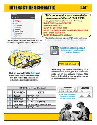
  • 1. Click here to view the Schematic Symbols and Definitions page INTERACTIVE SCHEMATIC The Bookmarks panel will allow you to quickly navigate to points of interest. Click on any text that is BLUE and underlined. These are hyperlinks that can be used to navigate the schematic and machine views. When only one callout is showing on a machine view, clicking on this button will make all of the callouts visible. This button is located in the top right corner of every machine view page. VIEW ALL CALLOUTS Cover Page Tables Schematic Machine Views Component Connector Chassis View Cab View Engine View Features Options Bookmarks X EC-C3 EC-C2 E-C60 EC-C1 E-C61 To set your screen resolution do the following: RIGHT CLICK on the DESKTOP. Select PROPERTIES. CLICK the SETTINGS TAB. MOVE THE SLIDER under SCREEN RESOLUTION until it shows 1024 X 768. CLICK OK to apply the resolution. *This document is best viewed at a screen resolution of 1024 X 768. *Due to different monitor sizes and PDF reader preferences there may be some variance in linked schematic locations FUNCTION Zoom In HOTKEYS (Keyboard Shortcuts) Zoom Out Fit to Page Hand Tool “CTRL” / “+” KEYS “CTRL” / “-” “CTRL” / “0” (zero) “SPACEBAR” (hold down) Find “CTRL” / “F” Pressure Switch Temperature Switch Level Switch Flow Switch Circuit Breaker T ELECTRICAL SYMBOLS Spring (Adjustable) Variability Fluid Conditioner Pump or Motor BASIC HYDRAULIC COMPONENT SYMBOLS Click here to save a copy of this interactive schematic to your desktop
  • 2. SCHEMATIC SYMBOLS AND DEFINITIONS HYDRAULIC SYMBOLS - ELECTRICAL Transducer (Fluid) Transducer (Gas / Air) G Generator Electrical Wire Pressure Switch M Electric Motor Pressure Switch (Adjustable) Temperature Switch Pressure Switch Temperature Switch Level Switch Flow Switch Circuit Breaker T ELECTRICAL SYMBOLS Spring Control Valves Restriction Line Restriction (Fixed) 2-Section Pump MAIN AUX. Spring (Adjustable) Variability Line Restriction (Variable) Pressure Compensation Pump: Variable and Pressure Compensated Hydraulic Pneumatic Energy Triangles Fluid Conditioner Attachment Pump or Motor BASIC HYDRAULIC COMPONENT SYMBOLS Line Restriction Variable and Pressure Compensated Vented Pressurized Return Above Fluid Level Return Below Fluid Level FLUID STORAGE RESERVOIRS Pressure Temperature Flow MEASUREMENT Unidirectional Bidirectional ROTATING SHAFTS One Position Two Position Three Position Two-way Three-Way Four-Way ENVELOPES PORTS CONTROL Basic Symbol Spring Loaded Normal Position A B P T A B P T Shifted Position Infinite Position Shuttle Pilot Controlled VALVES CHECK Solenoid or Manual Solenoid and Pilot Solenoid and Pilot or Manual Solenoid Servo Thermal Detent COMBINATION CONTROLS T Fuse: A component in an electrical circuit that will open the circuit if too much current flows through it. Switch (Normally Open): A switch that will close at a specified point (temp, press, etc.). The circle indicates that the component has screw terminals and a wire can be disconnected from it. Switch (Normally Closed): A switch that will open at a specified point (temp, press, etc.). No circle indicates that the wire cannot be disconnected from the component. Ground (Wired): This indicates that the component is connected to a grounded wire. The grounded wire is fastened to the machine. Ground (Case): This indicates that the component does not have a wire connected to ground. It is grounded by being fastened to the machine. Reed Switch: A switch whose contacts are controlled by a magnet. A magnet closes the contacts of a normally open reed switch; it opens the contacts of a normally closed reed switch. Sender: A component that is used with a temperature or pressure gauge. The sender measures the temperature or pressure. Its resistance changes to give an indication to the gauge of the temperature or pressure. Relay (Magnetic Switch): A relay is an electrical component that is activated by electricity. It has a coil that makes an electromagnet when current flows through it. The electromagnet can open or close the switch part of the relay. Solenoid: A solenoid is an electrical component that is activated by electricity. It has a coil that makes an electromagnet when current flows through it. The electromagnet can open or close a valve or move a piece of metal that can do work. Magnetic Latch Solenoid: An electrical component that is activated by electricity and held latched by a permanent magnet. It has two coils (latch and unlatch) that make electromagnet when current flows through them. It also has an internal switch that places the latch coil circuit open at the time the coil latches. BASIC ELECTRICAL COMPONENT SYMBOLS Push-pull Lever Pedal General Manual Push Button Spring Manual Shutoff MANUAL CONTROL External Return Internal Return Simplified Complete Internal Supply Pressure RELEASED PRESSURE REMOTE SUPPLY PRESSURE PILOT CONTROL Spring Loaded Gas Charged ACCUMULATORS Crossing Joining LINES Double Acting Single Acting CYLINDERS Unidirectional Bidirectional FIXED DISPLACEMENT VARIABLE DISPLACEMENT NON- COMPENSATED PUMPS Unidirectional Bidirectional Unidirectional Bidirectional FIXED DISPLACEMENT VARIABLE DISPLACEMENT NON- COMPENSATED MOTORS Unidirectional Bidirectional Two Position Infinite Positioning FLOW IN ONE DIRECTION FLOW ALLOWED IN EITHER DIRECTION Three Position CROSS FLOW PARALLEL FLOW INTERNAL PASSAGEWAYS 1 2 AG-C4 111-7898 L-C12 3E-5179 9X-1123 Component Part Number Pin or Socket Number Part Number: for Connector Plug Harness Identification Letter(s): (A, B, C, AA, AB, AC, ...) Plug 325-AG135 PK-14 Wire Color Wire Gauge Receptacle 1 1 2 2 Sure-Seal connector: Typical representation of a Sure-Seal connector. The plug and receptacle contain both pins and sockets. Deutsch connector: Typical representation of a Deutsch connector. The plug contains all sockets and the receptacle contains all pins. Fuse (5 Amps) 5A Harness identification code: This example indicates wire group 325, wire 135 in harness "AG". L-C12 3E-5179 Wire, Cable, or Harness Assembly Identification: Includes Harness Identification Letters and Harness Connector Serialization Codes (see sample). Harness Connector Serialization Code: The "C" stands for "Connector" and the number indicates which connector in the harness (C1, C2, C3, ...) HARNESS AND WIRE SYMBOLS
  • 3. © 2016 Caterpillar, All Rights Reserved Printed in U.S.A. DS41-UP Hydraulic System MD6540C Rotary Drill August 2016 UENR6873
  • 4. COMPONENT TABLE Description Part Number Schematic Location Machine Location Description Part Number Schematic Location Machine Location Cylinder - Cable Tensioning (Cab Side) 450-6484 D-10 1 Manifold - Supercharge 100-2953 B-12 50 Cylinder - Cable Tensioning (D/C Side) 450-6484 B-10 2 Motor - Drill (High Speed, Low Torque) 446-7390 G-11 51 Cylinder - Carousel Lock 1 462-3093 I-13 3 Motor - Drill (Low Speed, High Torque) 471-2902 G-10 52 Cylinder - Carousel Lock 2 462-3093 H-13 4 Motor - Engine Radiator Fan 420-1970 F-14 53 Cylinder - Carousel Rotate (4 POD) 408-6270 Motor - Final Drive (LH) 454-0811 E-11 54 Cylinder - Carousel Rotate (5 POD) 427-4976 Motor - Final Drive (RH) 454-0811 C-12 55 Cylinder - Cascading Stairs 438-534 J-3 6 Motor - HOC/COC Fan 419-935 F-13 56 Cylinder - Deck Wrench 427-164 J-13 7 Motor - Water Injection Bean Pump 479-5555 F-3 57 Cylinder - Front Dust Curtain 1 101-4058 J-7 8 Motor - Water Injection Bean Pump (Above Deck Option) 442-577 B-8 58 Cylinder - Front Dust Curtain 2 101-4058 J-7 9 Motor - Winch (16 Meter Mast) 166-7868 Cylinder - Front Jack (LH) 444-9756 F-7 10 Motor - Winch (20 Meter Mast) 471-7600 Cylinder - Front Jack (RH) 444-9756 G-7 11 Orifice - Cascading Stairs 433-914 J-4 60 Cylinder - Hobo Clamp 427-220 J-8 12 Orifice - Load Sense (AUX Pump) 414-8146 D-16 61 Cylinder - Hobo Rotate 427-221 I-8 13 Pump - Auxiliary 449-3689 C-16 62 Cylinder - Hobo Swing 427-219 I-9 14 Pump - Fan 459-9222 E-16 63 Cylinder - Main Air 439-628 I-6 15 Pump - Hand (Cascading Stairs) 438-763 J-3 64 Cylinder - Mast Lock 1 437-257 I-7 16 Pump - HVAC 459-9221 H-1 65 Cylinder - Mast Lock 2 437-257 J-7 17 Pump - Main (LH) 442-7706 D-15 66 Cylinder - Mast Raise 1 459-6706 H-6 18 Pump - Main (RH) 442-7706 B-15 67 Cylinder - Mast Raise 2 459-6706 H-5 19 Tank - Central Lube 157-7413 B-8 68 Cylinder - Pipe Catcher 1 101-4058 J-15 20 Tank - Hydraulic 460-1342 A-14 69 Cylinder - Pipe Catcher 2 101-4058 J-15 21 Valve - Aux Control 459-7667 H-3 70 Cylinder - Pipe Positioner Clamp 100-4269 I-16 22 Valve - Cascading Stairs Counter-Balance 420-708 J-5 71 Cylinder - Pipe Positioner Swing 100-4268 H-16 23 Valve - Check Drill Motor Case Drain 584-94 F-10 72 Cylinder - Pipe Rack Swing 1 426-859 J-1 24 Valve - Check Water Pump Motor 403-95 E-3 73 Cylinder - Pipe Rack Swing 2 426-859 J-10 25 Valve - Diverter (LH) 493-7514 E-12 74 Cylinder - Pipe Support Clamp 100-4269 I-14 26 Valve - Diverter (RH) 493-7514 C-12 75 Cylinder - Pipe Support Swing 100-4268 J-14 27 Valve - Fan Anti-Cavitation Check (COC/HOC 1) 423-0917 G-13 76 Cylinder - Pulldown 997-716 D-11 28 Valve - Fan Anti-Cavitation Check (COC/HOC 2) 423-0917 F-12 77 Cylinder - Rear Dust Curtain 1 461-3060 J-6 29 Valve - Fan Anti-Cavitation Check (Radiator 1) 423-0917 G-15 78 Cylinder - Rear Dust Curtain 2 461-3060 J-6 30 Valve - Fan Anti-Cavitation Check (Radiator 2) 423-0917 G-15 79 Cylinder - Rear Jack (LH) 443-6895 G-8 31 Valve - Fan Control Relief 1 422-044 E-16 80 Cylinder - Rear Jack (RH) 443-6895 F-8 32 Valve - Fan Control Relief 2 422-044 D-15 81 Cylinder - Viewing Hatch 461-3060 J-5 33 Valve - Flushing 431-873 C-11 82 Filter - Main Pump 1 (LH) 481-8634 E-13 34 Valve - Load Sense Shuttle 172-8240 D-15 83 Filter - Main Pump 1 (RH) 481-8634 C-13 35 Valve - Manually-Actuated Unloading (Cascading Stairs) 148-1404 J-4 84 Filter - Main Pump 2 (LH) 481-8634 D-13 36 Valve - Mast Control 169-6233 H-15 85 Filter - Main Pump 2 (RH) 481-8634 B-13 37 Valve - Mast Raise 441-1149 E-8 86 Filter - Tram Charge (Main Pump LH) 447-9785 E-14 38 Valve - Raise Counter-Balance 421-620 G-4 87 Filter - Tram Charge (Main Pump RH) 447-9785 C-14 39 Valve - Relief (Final Drive) LH 470-4114 E-13 88 Manifold - COC/HOC 423-9308 G-13 40 Valve - Relief (Final Drive) RH 470-4114 D-14 89 Manifold - Drain (Inside Tower Support) 441-3199 C-6 41 Valve - Relief (Hobo Clamp/Rotate 1) 101-4071 J-9 90 Manifold - Drain (Lower Mast D/C Side) 432-811 C-6 42 Valve - Relief (Hobo Clamp/Rotate 2) 101-4071 I-9 91 Manifold - Drain (Side Of Hydraulic Tank) 431-754 C-2 43 Valve - Relief (Hold-Back) 432-206 D-13 92 Manifold - Dust Collector Fan Motor 432-066 F-4 44 Valve - Relief (Pipe Positioner Clamp/Swing 1) 101-4071 I-15 93 Manifold - Fan Control 164-9540 F-15 45 Valve - Relief (Pipe Positioner Clamp/Swing 2) 101-4071 I-15 94 Manifold - Fan Return 419-924 G-12 46 Valve - Relief (Pipe Support Clamp/Swing 1) 101-4071 H-16 95 Manifold - Radiator 1 423-9308 G-14 47 Valve - Relief (Pipe Support Clamp/Swing 2) 101-4071 I-16 96 Manifold - Radiator 2 423-9308 G-14 48 Valve - Thermal Bypass 445-2771 F-12 97 Manifold - Return 430-225 E-2 49 Manifold - Cable, Brake, Diverter Control 151-4269 D-10 98 Component Locations H-8 5 F-8 59
  • 5. TAP TABLE Tap Number Description Schematic Location AP1 Mast Raise Aux Pressure E-4 AP2 Mast Raise Drain Pressure E-4 AP3 Aux Pump LS Relief Valve Pressure F-16 CP1 Main Pump RH Port X1 B-15 CP2 Main Pump RH Port X1 B-14 CP3 Main Pump LH Port X1 D-15 CP4 Main Pump LH Port X1 D-15 CP7 Cable Tension Valve Pressure E-10 CP8 Drill / Travel Valve Pressure E-10 CP9 Brake Valve Pressure E-10 DM1 Drian Manifold Pressure (Side of Hyd. Tank) C-2 FP1 Fan Control Relief Pressure 1 E-15 FP2 Fan Control Relief Pressure 2 E-15 FP3 Fan Anti-Cavitation Check Pressure 1 (COC/HOC) F-13 FP4 Fan Anti-Cavitation Check Pressure 2 (COC/HOC) F-13 FP5 Fan Anti-Cavitation Check Pressure 1 (Radiator) F-15 FP6 Fan Anti-Cavitation Check Pressure 2 (Radiator) F-14 FP7 Oil Fan Relief Valve Pressure G-16 FP9 Engine Fan Relief Valve Pressure F-16 HP1 Main Pump RH Output Pressure 1 B-14 HP2 Main Pump RH Output Pressure 2 B-14 HP3 Main Pump LH Output Pressure 1 D-14 HP4 Main Pump LH Output Pressure 2 D-14 R1 Fan Return Manifold Pressure G-12 R2 Return Drian Manifold Pressure E-1 SC Super Charge Manifold Pressure B-12 SUC Suction Block Pressure B-16 Tap Locations Pressure, Sampling, and Sensor
  • 6. UENR6873 42 Page, (Dimensions: 56 inches x 35 inches) Components are shown installed on a fully operable machine with the key and engine off, transmission shifter in neutral and with parking brake set. Refer to the appropriate Service Manual for Troubleshooting, Specifications and Systems Operations. SCHEMATIC PART NUMBER: 484-0436, CHANGE: XX, VERSION: XX THIS SCHEMATIC IS FOR THE MD6540C ROTARY DRILL HYDRAULIC SYSTEM MEDIA NUMBER: UENR6873 Refer to the Parts Manual using a specific serial number prefix in SIS before ordering parts from this schematic. A B C D E F 1 2 3 4 5 6 7 8 9 10 11 12 13 14 G H I J A B C D E F G H I J 15 16 1 2 3 4 5 6 7 8 9 10 11 12 13 14 15 16 HYDRAULIC CIRCUIT COLOR DESCRIPTIONS AUXILIARY PUMP OUTPUT MAIN PUMP OUTPUT CASCADING STAIRS CONTROL CIRCUIT VIEWING HATCH CYLINDER CONTROL CIRCUIT HOBO CYILNDERS CONTROL CIRCUIT DECK WRENCH CYLINDER CONTROL CIRCUIT FAN, SUPERCHARGER, AND DUST COLLECTOR CONTROL CIRCUIT SUPPLY LINE MAST RAISE CONTROL CIRCUIT JACK CYLINDERS CONTROL CIRCUIT MAST LOCK CYLINDER CONTROL CIRCUIT AIR CONDITIONER CONTROL CIRCUIT PIPE SUPPORT, RACK, CATCHER, AND POSTIONER CONTROL CIRCUIT DRAIN / RETURN LINE MAIN AIR CYLINDER CONTROL CIRCUIT CENTRAL LUBE TANK CONTROL CIRCUIT DUST CURTAIN CYLINDER CONTROL CIRCUIT WINCH CONTROL CIRCUIT CAROUSEL LOCK CYLINDER CONTROL CIRCUIT TRACK CONTROL CIRCUIT LINE PATTERNS Drain / Return Lines Component Group Pilot / Load Sensing Pressure Pressure Line CALLOUTS Taps (Pressure, Sampling, Sensor - by letter) YY (52) VALVE GP - CONTROL 138-1234 Callout Number (Machine Location from Component LocationsTable) Component Name Part Number Connectors (By letter) DL DL D FP1 FP2 HP2 HP1 HP3 HP4 SUC FP5 FP6 FP3 FP4 FP7 FP9 AP3 R1 SC AP1 AP2 CP7 CP8 CP9 CP1 CP2 CP3 CP4 DM1 R2 (1) CYLINDER CABLE TENSIONING (CAB SIDE) (2) CYLINDER CABLE TENSIONING (D/C SIDE) (3) CYLINDER CAROUSEL LOCK 1 (4) CYLINDER CAROUSEL LOCK 2 (5) CYLINDER CAROUSEL ROTATE (6) CYLINDER CASCADING STAIRS (7) CYLINDER DECK WRENCH (8) CYLINDER FRONT DUST CURTAIN 1 (9) CYLINDER FRONT DUST CURTAIN 2 (10) CYLINDER FRONT JACK (LH) (11) CYLINDER FRONT JACK (RH) (12) CYLINDER HOBO CLAMP (13) CYLINDER HOBO ROTATE (14) CYLINDER HOBO SWING (15) CYLINDER MAIN AIR (16) CYLINDER MAST LOCK 1 (17) CYLINDER MAST LOCK 2 (18) CYLINDER MAST RAISE 1 (19) CYLINDER MAST RAISE 2 (20) CYLINDER PIPE CATCHER 1 (21) CYLINDER PIPE CATCHER 2 (22) CYLINDER PIPE SUPPORT CLAMP (23) CYLINDER PIPE SUPPORT SWING (26) CYLINDER PIPE POSITIONER SWING (25) CYLINDER PIPE POSITIONER CLAMP (24) CYLINDER PIPE RACK SWING 1 (25) CYLINDER PIPE RACK SWING 2 (28) CYLINDER PULLDOWN (29) CYLINDER REAR DUST CURTAIN 1 (30) CYLINDER REAR DUST CURTAIN 2 (32) CYLINDER VIEWING HATCH (31) CYLINDER REAR JACK (LH) (32) CYLINDER REAR JACK (RH) (34) FILTER MAIN PUMP 1 (LH) (36) FILTER MAIN PUMP 2 (LH) (35) FILTER MAIN PUMP 1 (RH) (37) FILTER MAIN PUMP 2 (RH) (39) FILTER TRAM CHARGE MAIN PUMP 1 (RH) (40) MANIFOLD C0C/HOC (48) MANIFOLD RADIATOR 2 (47) MANIFOLD RADIATOR 1 (42) MANIFOLD DRAIN (LOWER MAST D/C SIDE) (41) MANIFOLD DRAIN (INSIDE TOWER SUPPORT) (43) MANIFOLD DRAIN (SIDE OF HYDRAULIC TANK) (44) MANIFOLD DUST COLLECTOR FAN MOTOR (45) MANIFOLD FAN CONTROL (97) VALVE THERMAL BYPASS (46) MANIFOLD FAN RETURN (49) MANIFOLD RETURN (50) MANIFOLD SUPERCHARGE (51) MOTOR DRILL (HIGH SPEED, LOW TORQUE) (52) MOTOR DRILL (LOW SPEED, HIGH TORQUE) (53) MOTOR ENGINE RADIATOR FAN (54) MOTOR FINAL DRIVE (LH) (55) MOTOR FINAL DRIVE (RH) (56) MOTOR HOC/COC FAN (57) MOTOR WATER INJECTION BEAN PUMP (58) MOTOR WATER INJECTION BEAN PUMP (ABOVE DECK OPTION) (59) MOTOR WINCH (60) ORIFICE CASCADING STAIRS (61) ORIFICE LOAD SENSE (AUX PUMP) (62) PUMP AUXILIARY (63) PUMP FAN (64) PUMP HAND (CASCADING STAIRS) (65) PUMP HVAC (66) PUMP MAIN (LH) (67) PUMP MAIN (RH) (69) TANK HYDRAULIC (68) TANK CENTRAL LUBE (70) VALVE AUX CONTROL (71) VALVE CASCADING STAIRS COUNTER-BALANCE (72) VALVE CHECK DRILL MOTOR CASE DRAIN (73) VALVE CHECK WATER PUMP MOTOR (74) VALVE DIVERTER (LH) (75) VALVE DIVERTER (RH) (77) VALVE FAN ANTI-CAVITATION CHECK (COC/HOC 2) (76) VALVE FAN ANTI-CAVITATION CHECK (COC/HOC 1) (78) VALVE FAN ANTI-CAVITATION CHECK (RADIATOR 1) (79) VALVE FAN ANTI-CAVITATION CHECK (RADIATOR 2) (80) VALVE FAN CONTROL RELIEF 1 (81) VALVE FAN CONTROL RELIEF 2 (82) VALVE FLUSHING (83) VALVE LOAD SENSE SHUTTLE (84) VALVE MANUALLY-ACTUATED UNLOADING (CASCADING STAIRS) (85) VALVE MAST CONTROL (86) VALVE MAST RAISE (87) VALVE RAISE COUNTER-BALANCE (88) VALVE RELIEF (FINAL DRIVE) LH (89) VALVE RELIEF (FINAL DRIVE) RH (90) VALVE RELIEF (HOBO CLAMP/ROTATE 1) (91) VALVE RELIEF (HOBO CLAMP/ROTATE 1) (92) VALVE RELIEF (HOLD BACK) (95) VALVE RELIEF (PIPE SUPPORT CLAMP/SWING 1) (96) VALVE RELIEF (PIPE SUPPORT CLAMP/SWING 2) (94) VALVE RELIEF (PIPE POSITIONER CLAMP/SWING 2) (93) VALVE RELIEF (PIPE POSITIONER CLAMP/SWING 1) (98) MANIFOLD CABLE, BRAKE, DIVERTER CONTROL (38) FILTER TRAM CHARGE MAIN PUMP 1 (LH) 450-6484 450-6484 462-3093 462-3093 (5 POD) 427-4976 (4 POD) 408-6270 538-534 427-164 101-4058 101-4058 444-9756 444-9756 427-220 427-221 427-219 439-628 437-257 437-257 459-6706 459-6706 101-4058 101-4058 100-4269 100-4268 100-4268 100-4269 426-859 426-859 997-716 461-3060 461-3060 461-3060 443-6895 443-6895 481-8634 481-8634 481-8634 481-8634 447-9785 447-9785 423-9308 423-9308 423-9308 432-811 441-3199 431-754 432-066 164-9540 445-2771 419-924 430-225 100-2953 446-7390 471-2902 471-2902 454-0811 454-0811 419-935 479-5555 442-577 (16 METER MAST) (20 METER MAST) 166-7868 166-7868 433-914 449-9222 449-3689 449-9222 438-763 459-9221 442-7706 442-7706 460-1342 157-7413 459-7667 420-708 584-94 403-95 493-7514 493-7514 423-0917 423-0917 423-0917 423-0917 422-044 422-044 431-873 172-8240 148-1404 169-6233 441-1149 421-620 470-4114 470-4114 101-4071 101-4071 432-206 101-4071 101-4071 101-4071 101-4071 151-4269 LOC: H-1 LOC: H-1
  • 8. MAST - FRONT VIEW 28 25 24 21 20 2 1 VIEW ALL CALLOUTS
  • 9. MACHINE - REAR A B C VIEW OF AREA “A” VIEW OF AREA “B” VIEW OF AREA “C” 96 95 92 73 59 52 51 27 26 7 5 4 3 VIEW ALL CALLOUTS
  • 10. MACHINE - REAR LEFT 94 93 91 90 85 68 42 23 22 14 13 12 9 8 VIEW ALL CALLOUTS
  • 12. HYDRAULICS - LEFT SIDE VIEW VIEW OF AREA “D” (ROTATED FOR CLARITY) D SUC HP4 HP3 HP2 HP1 FP9 FP7 FP2 FP1 DM1 CP9 CP8 CP7 CP4 CP3 CP2 CP1 AP3 SC R2 98 89 88 87 86 83 82 81 80 75 74 72 70 69 67 66 65 63 62 61 58 50 49 45 43 41 39 38 37 36 35 34 32 VIEW ALL CALLOUTS